ASRock 939Dual-SATA2 VCore & VDimm Voltmods |
|
|
Author: W1zzard
Date: 2005-11-04 11:24:14
|
|
VDimm Mod
Depending on your needs there are several ways to increase the memory voltage.
3.20V
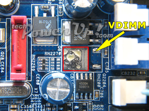
The red solder pad carries about 3.20V. If you bridge this solder pad to the VDIMM solder pad with a wire, you will directly feed the 3.20V into your memory.3.30V
If you need more voltage, you can route an orange wire (3.3V) from your ATX Power Connector and connect it directly to the solder pad.This mod is even more useful if you have a PSU with adjustable 3.3V rail, because changing the 3.3V rail will also change your memory voltage. With two memory modules about 3.5A will run through your wire during load, so make sure you do not use a too thin wire.
Variable Voltage

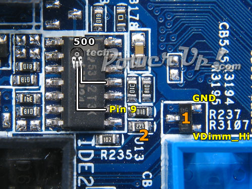
The BIOS setting VDimm controls the transistor "1". If the voltage in the BIOS is set to Normal, the transistor is closed. When set to High, the transistor is open and will drop the voltage seen on Pin 9 of the LM324. The resistance of resistor "2" will determine how big the dropout is.
The smaller the resistance, the higher the dropout, the higher the resulting memory voltage.
What we are going to do now is solder a trimmer to Pin 9 so we create a second dropout which we can manually control. Connect one pin of the variable resistor to Pin 9 and the other pin to Ground (Pin 11 works good, but any ground is fine).
I found a variable resistor of 500 Ohm works best. At 500 Ohm it will increase the memory voltage by 0.25V, this takes the BIOS setting into account.
Resistor at 500 Ohm: BIOS set to Normal results in 2.85V. BIOS set to High results in 2.95V.
The highest memory voltage you can reach with this mod is 3.05V, at 248 Ohm (BIOS Normal) or 316 Ohm (BIOS High).
Mar 25th, 2025 17:58 EDT
change timezone
Latest GPU Drivers
New Forum Posts
- Hotspot 110° (6)
- RX 9070 availability (231)
- Windows 11 General Discussion (5893)
- Question about Intel Optane SSDs (50)
- Did Nvidia purposely gimp the performance of 50xx series cards with drivers (37)
- Is RX 9070 VRAM temperature regular value or hotspot? (191)
- Motherboard for home/business NAS, which one should I get? (3)
- As we live the age of game remakes, which game you would like to see to have a remake? (369)
- maxsun rx590* vbios (8)
- Discussion/Testing: nVME USB drives vs. Backwards interface / Lesser hardware (4)
Popular Reviews
- Assassin's Creed Shadows Performance Benchmark Review - 30 GPUs Compared
- be quiet! Pure Rock Pro 3 Black Review
- ASUS ProArt X870E-Creator Wi-Fi Review
- ASRock Radeon RX 9070 XT Taichi OC Review - Excellent Cooling
- Sapphire Radeon RX 9070 XT Nitro+ Review - Beating NVIDIA
- ASUS GeForce RTX 5070 TUF OC Review
- AMD Ryzen 9 9950X3D Review - Great for Gaming and Productivity
- Pulsar Feinmann F01 Review
- AMD Ryzen 7 9800X3D Review - The Best Gaming Processor
- Quick Look: Jelly Key Mystic Snake Artisan Keycaps
Controversial News Posts
- AMD RDNA 4 and Radeon RX 9070 Series Unveiled: $549 & $599 (260)
- AMD Radeon RX 9070-series Pricing Leaks Courtesy of MicroCenter (158)
- MSI Doesn't Plan Radeon RX 9000 Series GPUs, Skips AMD RDNA 4 Generation Entirely (142)
- Microsoft Introduces Copilot for Gaming (123)
- AMD Radeon RX 9070 XT Reportedly Outperforms RTX 5080 Through Undervolting (118)
- NVIDIA Reportedly Prepares GeForce RTX 5060 and RTX 5060 Ti Unveil Tomorrow (115)
- Over 200,000 Sold Radeon RX 9070 and RX 9070 XT GPUs? AMD Says No Number was Given (100)
- NVIDIA GeForce RTX 5050, RTX 5060, and RTX 5060 Ti Specifications Leak (96)