 5
5
Cooler Master G550M 550 W Review
Voltage Regulation, Hold-up Time & Inrush Current »A Look Inside & Component Analysis
Before reading this page, we strongly suggest a look at this article, which will help you understand the internal components of a PSU much better. Our main tool for the disassembly of the PSU is a Thermaltronics TMT-9000S soldering and rework station. It is of extreme quality and is equipped with a matching de-soldering gun. With such equipment in hand, breaking apart every PSU is like a walk in the park!


This unit is made by Channel Well Technology, an OEM with a lot of experience and good overall products. The platform isn't cutting edge since Bronze efficiency can nowadays easily be achieved without any exotic components. The secondary side utilizes VRMs (Voltage Regulation Modules) for the generation of the minor rails, and the +12V rail is rectified by active components. Also, the PCB is small and not densely populated since the PSU's small capacity doesn't take many, or bulky, components.
The transient filter starts at the AC receptacle with one X and two Y caps. We also find a small IC which isolates the bleeding resistor of the C cap once the PSU starts—redistricting energy losses—on the solder side of the small PCB that holds the aforementioned components. All other components of the transient/EMI filter are located on the main PCB and consist of two X and two Y caps, two CM chokes, and an MOV.

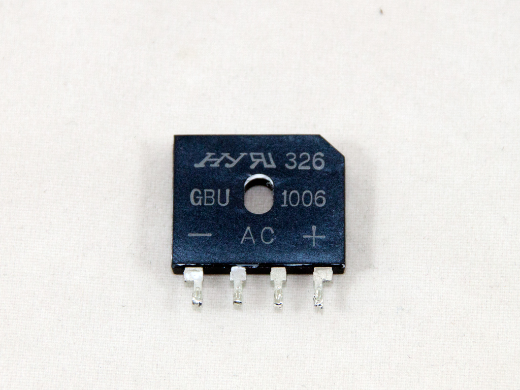
The bridge rectifier with model number GBU1006 is soldered to a small dedicated heatsink.


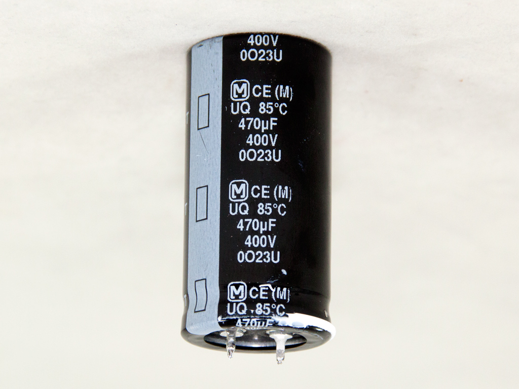

The APFC converter uses two SGF160N60W3 fets and a Power Integrations LXA08FP600 boost diode. The bulk cap is provided by Panasonic (400 V, 470 µF, 85°C), and its capacity looks alright for the needs of this unit; however, the NTC thermistor that protects against large inrush currents is rather small.

A couple of SGF190N60SJ fets are used as main switchers.

The standby PWM controller is a TNY177PN IC.


A synchronous design is used for the rectification of the +12V rail on the secondary side, and three SG65N0PFR fets handle this rail. The filtering caps here are mostly CapXon electrolytics, but we also found a single Jun Fu (not Kung Fu!) cap. CM apparently tried to save on cost here by going with such mediocre caps, which we didn't like, but it will ultimately be their problem if something goes wrong given they cover this product with a pretty long warranty.


Both VRMs generating the minor rails are housed on the same PCB. The common PWM controller is an APW7159 IC, and two pairs of M3004D and M3006D fets are used along with it.


We find another Jun Fu cap and several CapXon (also known as CrapXon) ones on the front of the modular PCB.

The supervisor IC is soldered to the main PCB and is a Sitronix ST9S429-PG14; it has two OCP +12V channels and doesn't include OTP (Over Temperature Protection), so the latter must be implemented via another way.


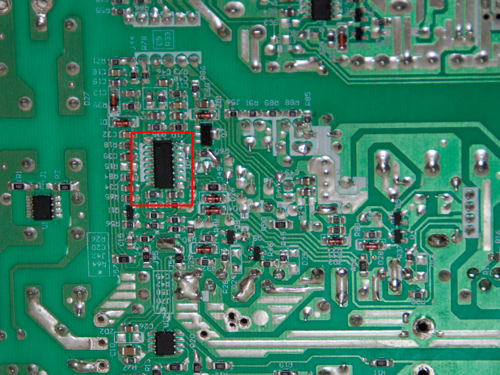
Soldering quality is decent overall and we spotted the combo PFC/PWM controller—it is mostly found on older designs or lower efficiency PSUs, like the Champion CM6800TX.

The cooling fan is provided by Yate Loon, and its model number is D12BH-12 (120 mm, 12 V, 0.3 A, 2300 RPM, 89 CFM, 41 dBA). It uses ball bearings and is pretty strong for a 550 W PSU, even for a Bronze efficiency one. Its fan profile is thankfully pretty relaxed, so it will spin at very low speeds for very little noise at normal loads and temperatures.
Jul 30th, 2025 14:08 CDT
change timezone
Latest GPU Drivers
New Forum Posts
- Your PC ATM (35561)
- AI Job Losses: let's count the losses up, total losses to AI so far 94,000 and counting (87)
- Looking To Make List Of Keyboard Manufacturers (33)
- Question corrupta filés in wi-fi download (11)
- 3D Printer Club (575)
- TPU's Nostalgic Hardware Club (20583)
- TechPowerUp Screenshot Thread (MASSIVE 56K WARNING) (4283)
- LCD IPS display (21)
- What CPU should I upgrade to from a 5 3600 to match 7700XT? Upgrade entire platform? (6)
- What's your latest tech purchase? (24403)
Popular Reviews
- MSI Claw 8 AI+ A2VM Review
- Herman Miller Logitech G Embody Review - No Pain, No Gain
- Lenovo Legion 5i (15IRX10) Review - Feature-Rich and Wallet Friendly
- Lian Li O11 Dynamic Mini V2 Review
- Upcoming Hardware Launches 2025 (Updated May 2025)
- Noctua NF-A12x25 G2 PWM Fan Review
- Orbital Pathfinder Review
- Sapphire Radeon RX 9060 XT Pulse OC 16 GB Review - An Excellent Choice
- AMD Ryzen 7 9800X3D Review - The Best Gaming Processor
- AQIRYS Sirius Pro Review
TPU on YouTube
Controversial News Posts
- AMD's Upcoming UDNA / RDNA 5 GPU Could Feature 96 CUs and 384-bit Memory Bus (136)
- AMD Radeon RX 9070 XT Gains 9% Performance at 1440p with Latest Driver, Beats RTX 5070 Ti (131)
- Intel "Nova Lake-S" Core Ultra 3, Ultra 5, Ultra 7, and Ultra 9 Core Configurations Surface (110)
- DDR6 Memory Arrives in 2027 with 8,800-17,600 MT/s Speeds (101)
- AMD Sampling Next-Gen Ryzen Desktop "Medusa Ridge," Sees Incremental IPC Upgrade, New cIOD (97)
- Intel CEO Confirms SMT To Return to Future CPUs (95)
- NVIDIA Becomes First Company Ever to Hit $4 Trillion Market-Cap (94)
- AMD Radeon AI PRO R9700 GPU Arrives on July 23rd (90)