 4
4
Aerocool GT-SG 700 W Review
Ripple Measurements »Advanced Transient Response Tests
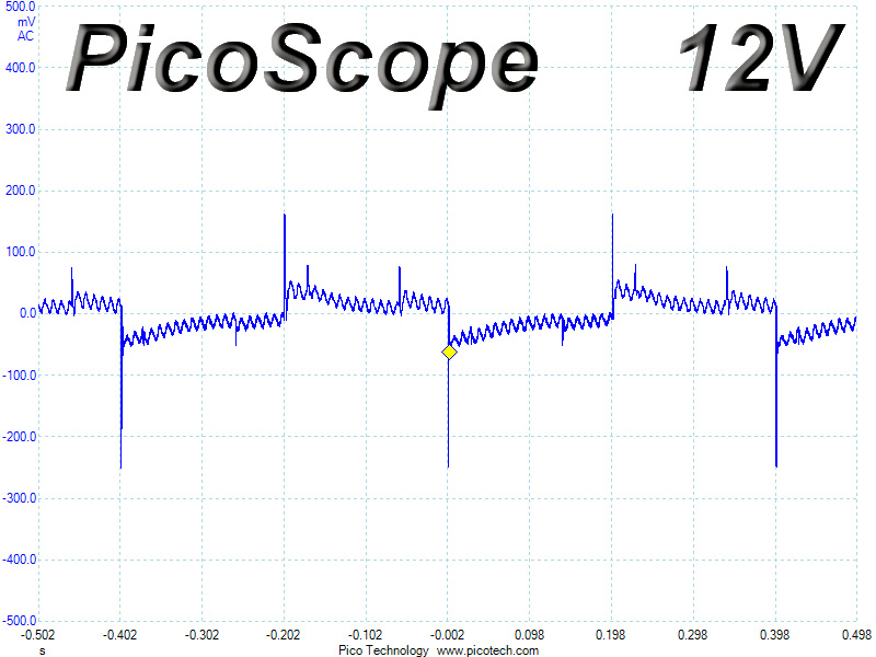
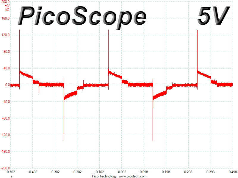
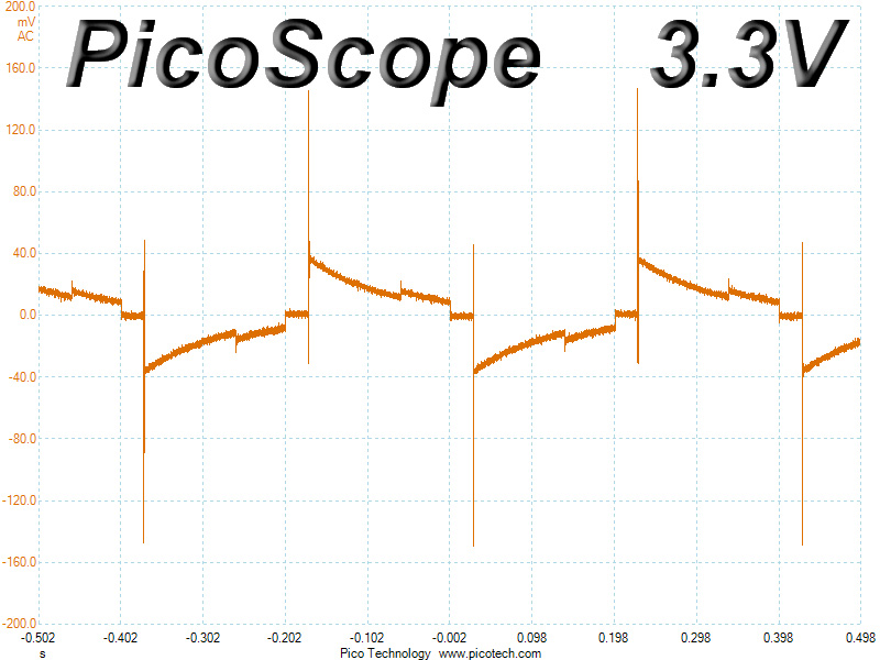
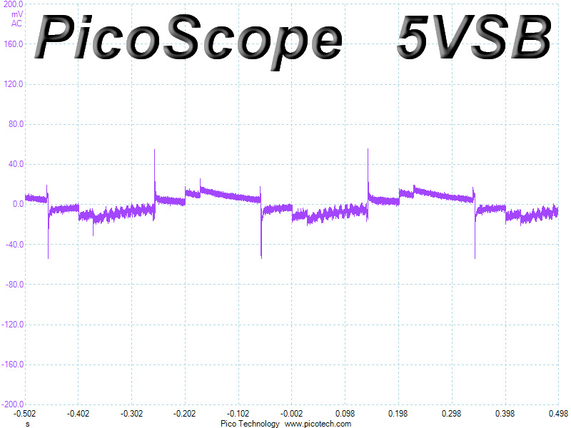
In these tests, we monitor the response of the PSU in two different scenarios. First, a transient load (10 A at +12V, 5 A at 5V, 5 A at 3.3V, and 0.5 A at 5VSB) is applied to the PSU for 200 ms while the latter is working at a 20% load state. In the second scenario, the PSU, while working at 50% load, is hit by the same transient load. In both tests, we measure the voltage drops that the transient load causes using our oscilloscope. The voltages should remain within the regulation limits defined by the ATX specification. We must stress here that the above tests are crucial since they simulate transient loads that a PSU is very likely to handle (e.g., booting a RAID array, an instant 100% load of CPU/VGAs, etc.) We call these tests "Advanced Transient Response Tests", and they are designed to be very tough to master, especially for PSUs with capacities lower than 500 W.| Advanced Transient Response 20% | ||||
|---|---|---|---|---|
| Voltage | Before | After | Change | Pass/Fail |
| 12 V | 12.122V | 11.871V | 2.07% | Pass |
| 5 V | 5.100V | 4.965V | 2.65% | Pass |
| 3.3 V | 3.408V | 3.259V | 4.37% | Pass |
| 5VSB | 5.071V | 5.017V | 1.06% | Pass |
| Advanced Transient Response 50% | ||||
|---|---|---|---|---|
| Voltage | Before | After | Change | Pass/Fail |
| 12 V | 12.040V | 11.909V | 1.09% | Pass |
| 5 V | 5.067V | 4.932V | 2.66% | Pass |
| 3.3 V | 3.374V | 3.227V | 4.36% | Pass |
| 5VSB | 5.037V | 4.978V | 1.17% | Pass |
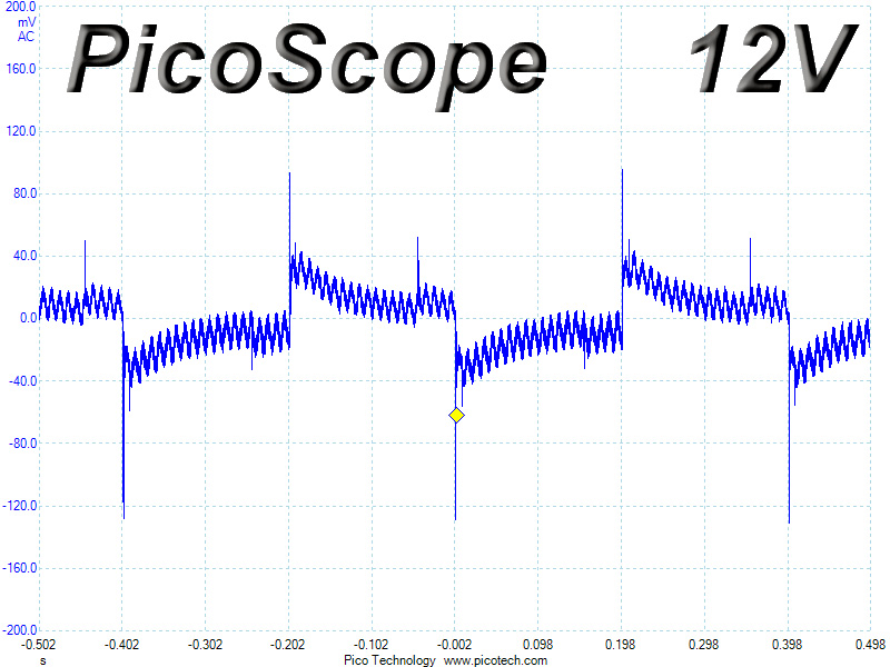
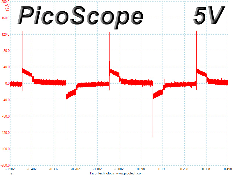
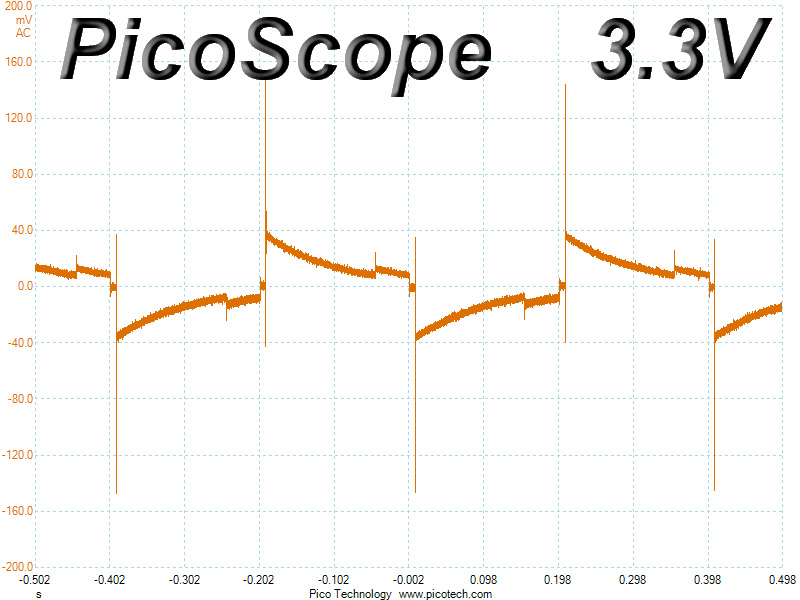
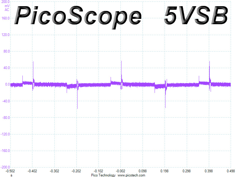
Voltage drops were well controlled on all rails; however, at 3.3V the registered deviation exceeded 4%. Nevertheless, what matters the most with these tests is the response of the +12V rail and its response was very good. During the first test, the deviation on the aforementioned rail was higher than on the second test because the main switchers at low loads operate in PWM mode.
Below, you will find the oscilloscope screenshots that we took during Advanced Transient Response Testing.
Transient Response at 20% Load
Transient Response at 50% Load
Turn-On Transient Tests
We measure the response of the PSU in simpler scenarios of transient loads - during the power-on phase of the PSU - in the next set of tests. In the first test, we turn the PSU off, dial the maximum current that the 5VSB can output, and then switch on the PSU. In the second test, we dial the maximum load that +12V can handle and we start the PSU while the PSU is in standby mode. In the last test, while the PSU is completely switched off (we cut off power or switch off the PSU's on/off switch), we dial the maximum load that the +12V rail can handle before switching the PSU on from the loader and restoring power. The ATX specification states that recorded spikes on all rails should not exceed 10% of their nominal values (e.g., +10% for 12V is 13.2V and for 5.5V is 5V).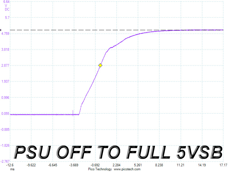
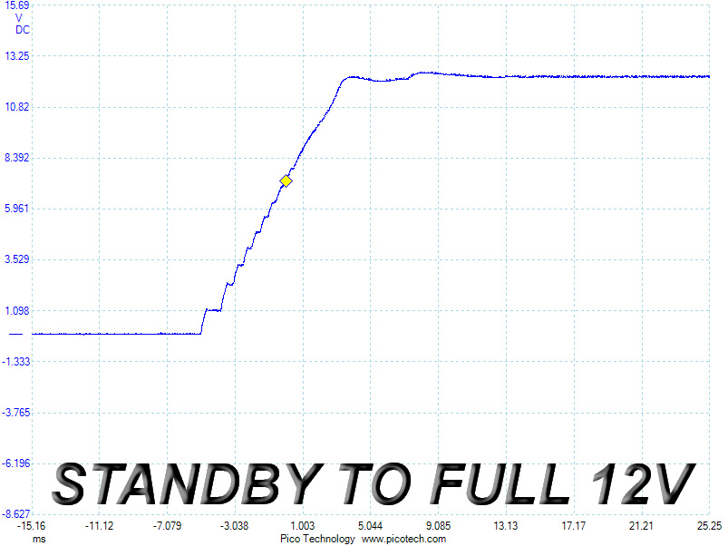
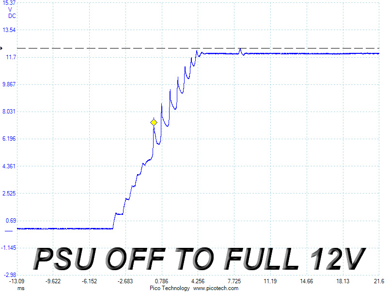
The slope is ideal at 5VSB; however, we noticed some voltage overshoots and steps in the slope on the second test (standby to full +12V). The worst results were registered during the last test (off to full +12V) where some really nasty spikes spoiled the picture. Normally, the slope would ramp up smoothly, but the last screenshot clearly shows that such is not the case.
Feb 8th, 2025 19:09 EST
change timezone
Latest GPU Drivers
New Forum Posts
- Starting my AM5 build (46)
- What are you playing? (22811)
- Help choosing a GPU (30)
- New F@H Team Members Post Here First (824)
- DLSS 4 is better than native resolution? (36)
- RTX 5080 - premature review - it sucks (341)
- Problem with GPU (3)
- Xeon Owners Club (8861)
- RTX5000 Series Owners Club (73)
- Free Games Thread (4436)
Popular Reviews
- Kingdom Come Deliverance II Performance Benchmark Review - 35 GPUs Tested
- Civilization VII Performance Benchmark Review - 35 GPUs Tested
- Kingdom Come: Deliverance 2 Handheld Performance Review
- ASUS ROG Harpe Ace Extreme Review
- Spider-Man 2 Performance Benchmark Review - 35 GPUs Tested
- ASRock Phantom Gaming B850I Lightning Wi-Fi Review
- Formovie Cinema Edge 4K UST Laser Projector Review
- NVIDIA GeForce RTX 5080 Founders Edition Review
- AMD Ryzen 7 9800X3D Review - The Best Gaming Processor
- Corsair Frame 4000D Review
Controversial News Posts
- AMD Radeon 9070 XT Rumored to Outpace RTX 5070 Ti by Almost 15% (286)
- AMD is Taking Time with Radeon RX 9000 to Optimize Software and FSR 4 (256)
- AMD Denies Radeon RX 9070 XT $899 USD Starting Price Point Rumors (239)
- Edward Snowden Lashes Out at NVIDIA Over GeForce RTX 50 Pricing And Value (235)
- AMD Radeon RX 9070 XT & RX 9070 Custom Models In Stock at European Stores (226)
- New Leak Reveals NVIDIA RTX 5080 Is Slower Than RTX 4090 (215)
- AMD's Radeon RX 9070 Launch Faces Pricing Hurdles (175)
- AMD Radeon RX 9070 XT Tested in Cyberpunk 2077 and Black Myth: Wukong (169)