 2
2
DFI LanParty UT NF4 Ultra-D Review
Layout continued »Board Layout
Click here for a 3000x2500 high-res shot of the board (3 MB download), the backside is here.
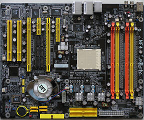
There is plenty of space around the CPU area. All MOSFETs have heatsinks on them to reduce thermal stress.
PS/2 Keyboard, PS/2 Mouse, SPDIF, Audio, Dual Gigabit Ethernet, six USB Ports. On the backside panel the most important connectors are included. The layout does not really follow the ATX specification, except for the PS/2 ports and the networking. But since an IO shield is included this is no big issue.
The motherboard's memory slots have been color coded for easy dual-channel configuration. To run your memory in dual-channel mode you have to put the modules into slots of the same color.
Connectors
Both the 24-pin ATX power connector and the ATX12V connector are placed in the best possible location I could imagine. Great work on this, DFI.
If you think your board needs more juice, DFI has added a 3.5" Floppy and a 5.25" Power connector the board. These supply additional power to the motherboard and help reduce the stress on the regular ATX power cables. Electrically, the 12V of ATX Power, ATX12V, 5.25" and 3.5" are connected together, same for the 5V line.
You will find two parallel ATA ports on this motherboard, for a total of four IDE devices. Both ports are provided by the nForce4 chipset and are spec'd to run at up to 133 MB/s.
While SATA-II is not much of a performance improvement, having four 300 MB/s capable ports is definitely a nice thing. The 90° angled connector is for the floppy, if you are one of the last people on this planet to use them. The HDDs can also be run in RAID 0, RAID 1 or RAID 0+1.
Some manufacturers color-code the Reset/Power/LED connectors, so it is easier to spot which pins belong together. DFI does not do this, but the pins are clearly labelled.
DFI has added a load of jumpers all over the board. While the other ones deal with SPDIF and USB power, these three are certainly more interesting.
From left to right:
Safe Boot: In case you are unable to start your system during your overclocking adventures, you switch this jumper to the 2-3 position when the system is powered down, wait a few seconds then switch it back to 1-2. Now all overclocking settings are reset, while the other CMOS settings are saved.
Speaker On/Off: Having a PC speaker onboard is crucial when it comes to detecting bootup problems. For day to day usage it might be annoying. switching this jumper into position 1-2 disables the onboard speaker. This is the default position. In my opinion it would have made more sense to enable it by default, since during the first install, there could be some problems.
Clear CMOS: When this jumper is set to 2-3 it will clear all contents of the CMOS. This is useful when the system does not boot or after upgrading your BIOS.
Another useful jumper is this block. In the default position, the memory voltage is generated from the 3.3V supply. In case you want to run your memory at a higher voltage you switch this jumper to position 2-3 and the range of possible DDR voltages is increased up to 4.0V. The heatsink you see on the picture, is cooling the DDR Voltage MOSFET, on the 4V setting it tends to get very hot. If you don't need more than 3.3V on your memory, better go with the 3.3V setting where you won't have to worry about MOSFET heat.
One of the most wanted features by overclockers are those little push buttons. One button is for power, the other one for reset. For quick builds this saves you from connecting switches to the headers, or using screwdriver to turn on the system. I like the buttons DFI used a lot, they are big and have a clearly defined switch-point.
Feb 11th, 2025 14:31 EST
change timezone
Latest GPU Drivers
New Forum Posts
- What are you playing? (22853)
- WCG Daily Numbers (12760)
- Proposed new Power Connector (13)
- How does MS Store remember my previous apps? (5)
- It's happening again, melting 12v high pwr connectors (207)
- TPU's Rosetta Milestones and Daily Pie Thread (2186)
- Overclocking Xeon 2690(v2) (23)
- Which SSD enclosure to buy? (12)
- How to move from one Boinc Crunching Team to another? (3)
- Folding Pie and Milestones!! (9370)
Popular Reviews
- Civilization VII Performance Benchmark Review - 35 GPUs Tested
- Kingdom Come Deliverance II Performance Benchmark Review - 35 GPUs Tested
- ASRock Phantom Gaming B850I Lightning Wi-Fi Review
- Team Group T-Force XTREEM DDR5-7200 48GB CL34 Review
- Spider-Man 2 Performance Benchmark Review - 35 GPUs Tested
- NVIDIA GeForce RTX 5080 Founders Edition Review
- AMD Ryzen 7 9800X3D Review - The Best Gaming Processor
- DAREU A980 Pro Max Review
- Kingdom Come: Deliverance 2 Handheld Performance Review
- Corsair Frame 4000D Review
Controversial News Posts
- AMD Radeon 9070 XT Rumored to Outpace RTX 5070 Ti by Almost 15% (286)
- AMD is Taking Time with Radeon RX 9000 to Optimize Software and FSR 4 (256)
- AMD Denies Radeon RX 9070 XT $899 USD Starting Price Point Rumors (239)
- Edward Snowden Lashes Out at NVIDIA Over GeForce RTX 50 Pricing And Value (239)
- AMD Radeon RX 9070 XT & RX 9070 Custom Models In Stock at European Stores (226)
- New Leak Reveals NVIDIA RTX 5080 Is Slower Than RTX 4090 (215)
- AMD's Radeon RX 9070 Launch Faces Pricing Hurdles (175)
- AMD Radeon RX 9070 XT Tested in Cyberpunk 2077 and Black Myth: Wukong (169)


