 5
5
SilverStone Strider Plus ST60F-PS 600 W Review
Ripple Measurements »Advanced Transient Response Tests
In these tests, we monitor the response of the PSU in two different scenarios. First, a transient load (10 A at +12V, 5 A at 5V, 5 A at 3.3V, and 0.5 A at 5VSB) is applied to the PSU for 200 ms while the latter is working at a 20% load state. In the second scenario, the PSU, while working at 50% load, is hit by the same transient load. In both tests, we measure the voltage drops that the transient load causes using our oscilloscope. The voltages should remain within the regulation limits defined by the ATX specification. We must stress here that the above tests are crucial since they simulate transient loads that a PSU is very likely to handle (e.g., booting a RAID array, an instant 100% load of CPU/VGAs, etc.) We call these tests "Advanced Transient Response Tests", and they are designed to be very tough to master, especially for PSUs with capacities lower than 500 W.| Advanced Transient Response 20% | ||||
|---|---|---|---|---|
| Voltage | Before | After | Change | Pass/Fail |
| 12 V | 12.441V | 12.052V | 3.13% | Pass |
| 5 V | 5.165V | 4.995V | 3.29% | Pass |
| 3.3 V | 3.326V | 3.189V | 4.12% | Pass |
| 5VSB | 5.112V | 5.066V | 0.90% | Pass |
| Advanced Transient Response 50% | ||||
|---|---|---|---|---|
| Voltage | Before | After | Change | Pass/Fail |
| 12 V | 12.361V | 12.166V | 1.58% | Pass |
| 5 V | 5.110V | 4.939V | 3.35% | Pass |
| 3.3 V | 3.283V | 3.147V | 4.14% | Pass |
| 5VSB | 5.050V | 5.016V | 0.67% | Pass |
The first test showed increased deviations on the +12V rail; that is, compared to those registered on the second test. The performance of the 3.3V rail didn't satisfy us, since its voltage dropped below 3.2V in both cases, and 3.3V also came very close to the lower limit on the second test.
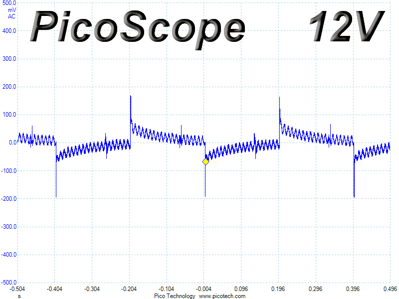
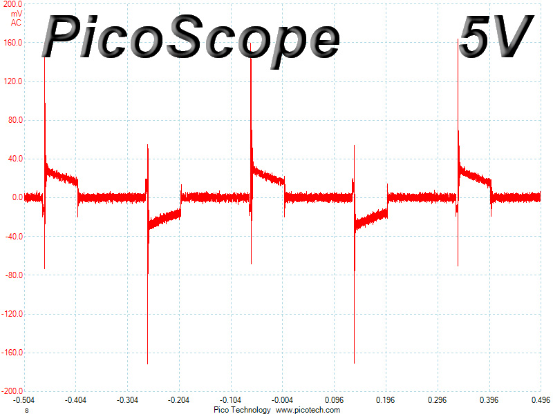
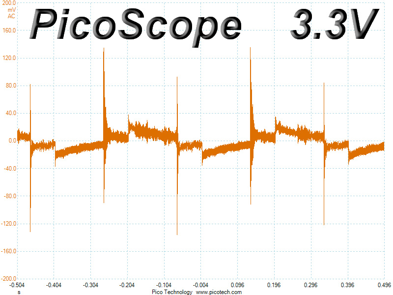
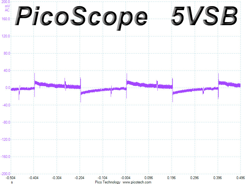
Below, you will find the oscilloscope screenshots that we took during Advanced Transient Response Testing.
Transient Response at 20% Load

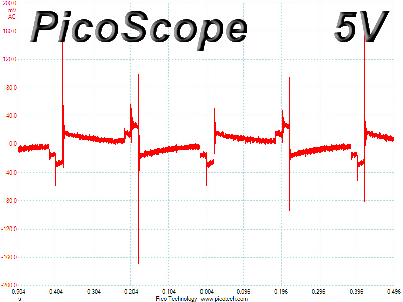
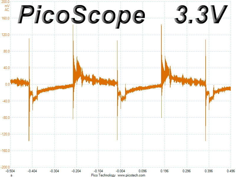
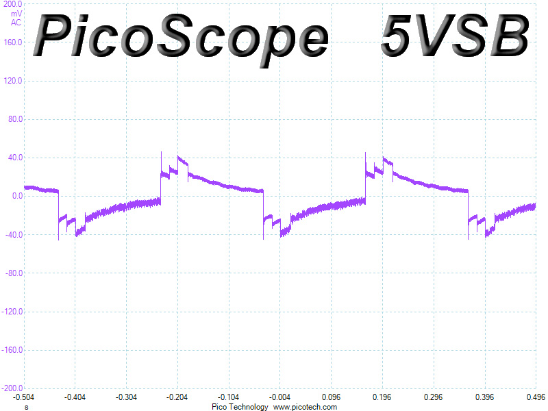
Transient Response at 50% Load
Turn-On Transient Tests
We measure the response of the PSU in simpler scenarios of transient loads - during the power-on phase of the PSU - in the next set of tests. In the first test, we turn the PSU off, dial the maximum current that the 5VSB can output, and then switch on the PSU. In the second test, we dial the maximum load that +12V can handle and we start the PSU while the PSU is in standby mode. In the last test, while the PSU is completely switched off (we cut off power or switch off the PSU's on/off switch), we dial the maximum load that the +12V rail can handle before switching the PSU on from the loader and restoring power. The ATX specification states that recorded spikes on all rails should not exceed 10% of their nominal values (e.g., +10% for 12V is 13.2V and 5.5V for 5V).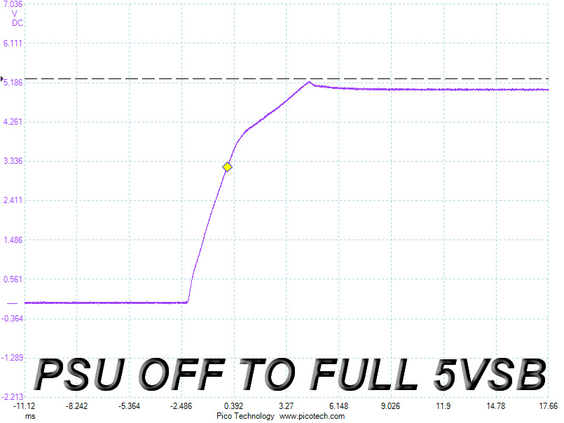
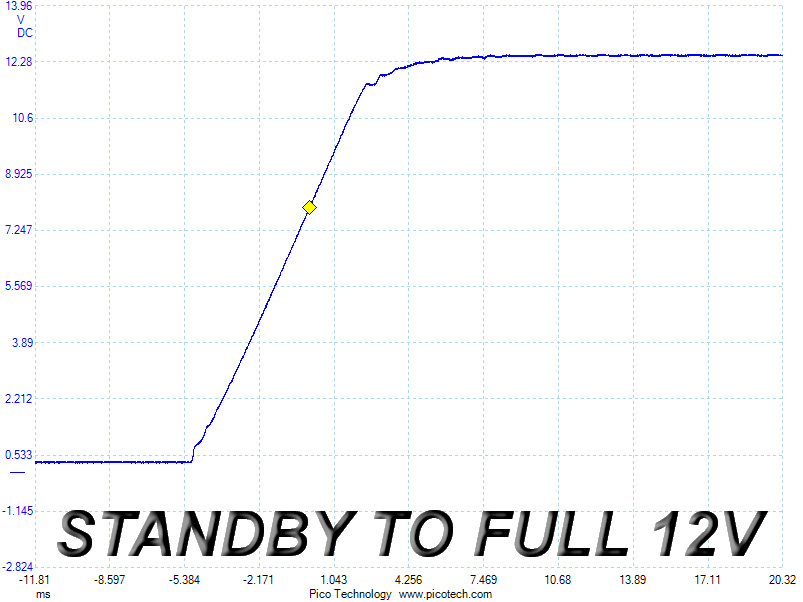
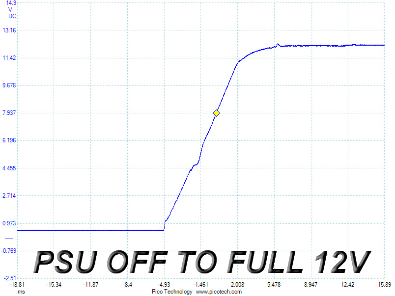
We measured a small voltage overshoot at 5VSB, but it is way below the corresponding limit. We didn't measure any voltage overshoots at +12V on the other two tests; however, we noticed a few minor spikes, but they are nothing to lose sleep over.
Mar 12th, 2025 07:58 EDT
change timezone
Latest GPU Drivers
New Forum Posts
- Post your Old CDs & FDs, from back in the day thread. (59)
- RX 9070 availability (211)
- Core i7 12700k or Ryzen 7 7700? (11)
- Nvidia's GPU market share hits 90% in Q4 2024 (gets closer to full monopoly) (872)
- Zen6 is almost here ? (52)
- TPU's Nostalgic Hardware Club (20085)
- Please I need help with the poor performance that my PC is giving me (36)
- HOW TO ADD NVMe M.2 SSD SUPPORT TO OLD MOTHERBOARDS WITH AMI BIOS LEGACY SUPPORT? (6)
- 2022-X58/1366 PIN Motherboards NVME M.2 SSD BIOS MOD Collection (906)
- Windows 11 General Discussion (5857)
Popular Reviews
- AMD Ryzen 9 9950X3D Review - Great for Gaming and Productivity
- XFX Radeon RX 9070 XT Mercury OC Magnetic Air Review
- Sapphire Radeon RX 9070 XT Nitro+ Review - Beating NVIDIA
- ASUS Radeon RX 9070 TUF OC Review
- Dough Spectrum Black 32 Review
- MSI MAG B850 Tomahawk Max Wi-Fi Review
- AMD Ryzen 7 9800X3D Review - The Best Gaming Processor
- NVIDIA GeForce RTX 5070 Founders Edition Review
- Corsair Vengeance RGB CUDIMM DDR5-8800 48 GB CL42 Review
- XPG Starker Air BTF Review
Controversial News Posts
- NVIDIA GeForce RTX 50 Cards Spotted with Missing ROPs, NVIDIA Confirms the Issue, Multiple Vendors Affected (513)
- AMD Radeon RX 9070 and 9070 XT Listed On Amazon - One Buyer Snags a Unit (261)
- AMD RDNA 4 and Radeon RX 9070 Series Unveiled: $549 & $599 (260)
- AMD Mentions Sub-$700 Pricing for Radeon RX 9070 GPU Series, Looks Like NV Minus $50 Again (248)
- NVIDIA Investigates GeForce RTX 50 Series "Blackwell" Black Screen and BSOD Issues (244)
- AMD Radeon RX 9070 and 9070 XT Official Performance Metrics Leaked, +42% 4K Performance Over Radeon RX 7900 GRE (195)
- AMD Radeon RX 9070-series Pricing Leaks Courtesy of MicroCenter (158)
- AMD Radeon RX 9070 XT Could Get a 32 GB GDDR6 Upgrade (100)