 1
1
Jou Jye BITWIN BW-B430JL 430W Review
Ripple Measurements »Advanced Transient Response Tests
In these tests we monitor the response of the PSU two two different scenarios. First a transient load (10A at +12V, 5A at 5V and 6A at 3.3V) is applied for 50 ms to the PSU, while the latter is working at a 20% load state. In the second scenario the PSU, while working with 50% load, is hit by the same transient load (with the exception now that load at 3.3V is increased by 4A). In both tests, we measure the voltage drops that the transient load causes, using a Labjack that is attached to our loader and the Stingray oscilloscope. In any case voltages should remain within the regulation limits specified by the ATX specification. We must stress here, that the above tests are crucial, since they simulate transient loads that a PSU is very likely to handle (e.g. starting of a RAID array, an instant 100% load of CPU/VGAs etc.) We call these tests “Advanced Transient Tests” and they are designed to be very tough to master, especially for PSUs with capacities lower than 500W.| Advanced Transient Response 20% | ||||
|---|---|---|---|---|
| Voltage | Before | After | Change | Pass/Fail |
| 12 V | 12.249V | 12.131V | 0.96% | Pass |
| 5 V | 5.055V | 4.920V | 2.67% | Pass |
| 3 V | 3.338V | 3.160V | 5.33% | Pass |
| 5VSB | 5.032V | 4.967V | 1.29% | Pass |
| Advanced Transient Response 50% | ||||
|---|---|---|---|---|
| Voltage | Before | After | Change | Pass/Fail |
| 12 V | 12.280V | 12.187V | 0.76% | Pass |
| 5 V | 4.945V | 4.801V | 2.91% | Pass |
| 3 V | 3.281V | 2.897V | 11.70% | Fail |
| 5VSB | 4.982V | 4.936V | 1.93% | Pass |
Wow! In the second part of our testing, the 3.3V rail dropped dead low, falling even under 2.9V! This is quite a voltage drop! It's been a very long time since I saw something similar. Thankfully the other two rails saved the day since voltage drops on them were small.
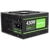
Below you will find the oscilloscope screenshots that we took during Advanced Transient Response Testing.
Transient Response at 20% Load

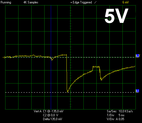
Transient Response at 50% Load


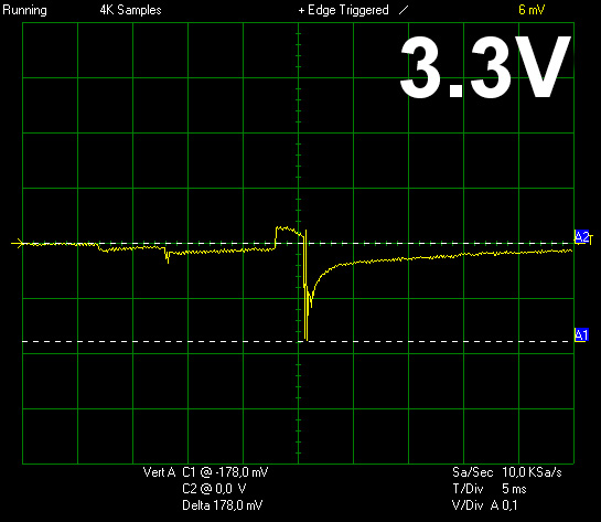
Turn-On Transient Tests
In the next set of tests we measure the response of the PSU in simpler scenarios of transient loads, during the turn on phase of the PSU. In the first test we turn off the PSU, dial 2A load at 5VSB and then switch on the PSU. In the second test, while the PSU is in standby, we dial the maximum load that +12V can handle and we start the PSU. In the final test, while the PSU is completely switched off (we cut off power or switch off the back switch), we dial the maximum load that +12V can handle, we then switch on the PSU from the loader and we restore power. The ATX specification states that recorded spikes on all rails should not exceed 10% of their nominal values (e.g. +10% for 12V is 13.2V and for 5V is 5.5V).

We noticed only a minor spike at the 5VSB rail. The +12V rail, in both tests we run, did not register any spikes. Finally the rise time* in all three tests is within ATX spec.
*Rise time, according to ATX spec, is defined as the time it takes any output voltage to rise from 10% to 95% of its nominal voltage. It must be between 0.2 - 20 ms.
May 15th, 2024 17:52 EDT
change timezone
Latest GPU Drivers
New Forum Posts
- Youtube, Discord, Visual Studio Code are flickering with black checkered squares/vertical lines. Partial solutions to this issue. (399)
- Alphacool CORE 1 CPU block - bulging with danger of splitting? (104)
- Is the FSP Hyper Pro H3-550 Model Good? (1)
- Prochot 95c turning red even though temperatures are not even close at around 50-65C? (1)
- 20 Years? (6)
- Is it normal to hear this sound coming from the psu? (33)
- RMAd every single component in my PC, and it's still crashing (10)
- FID when c-state is enabled (1)
- Post your Cinebench 2024 score (460)
- Immortals of Aveum deserves a second chance, the new free demo has convinced me. (45)
Popular Reviews
- Homeworld 3 Performance Benchmark Review - 35 GPUs Tested
- Enermax REVOLUTION D.F. X 1200 W Review
- ZMF Caldera Closed Planar Magnetic Headphones Review
- Lofree Edge Ultra-Low Profile Wireless Mechanical Keyboard Review
- Upcoming Hardware Launches 2023 (Updated Feb 2024)
- Corsair MP700 Pro SE 4 TB Review
- AMD Ryzen 7 7800X3D Review - The Best Gaming CPU
- ThundeRobot ML903 NearLink Review
- Bykski CPU-XPR-C-I CPU Water Block Review - Amazing Value!
- ASUS Radeon RX 7900 GRE TUF OC Review
Controversial News Posts
- Intel Statement on Stability Issues: "Motherboard Makers to Blame" (267)
- AMD to Redesign Ray Tracing Hardware on RDNA 4 (227)
- Windows 11 Now Officially Adware as Microsoft Embeds Ads in the Start Menu (172)
- NVIDIA to Only Launch the Flagship GeForce RTX 5090 in 2024, Rest of the Series in 2025 (152)
- AMD Hits Highest-Ever x86 CPU Market Share in Q1 2024 Across Desktop and Server (137)
- AMD RDNA 5 a "Clean Sheet" Graphics Architecture, RDNA 4 Merely Corrects a Bug Over RDNA 3 (118)
- AMD's RDNA 4 GPUs Could Stick with 18 Gbps GDDR6 Memory (114)
- AMD Ryzen 9 7900X3D Now at a Mouth-watering $329 (104)