• Welcome to TechPowerUp Forums, Guest! Please check out our forum guidelines for info related to our community.

ASUS TUF Gaming B760M-BTF WiFi D4 has its Connectors on the Reverse Side of the Motherboard

TheLostSwede

News Editor
Joined
Nov 11, 2004
Messages
18,491 (2.47/day)
Location
Sweden
System Name Overlord Mk MLI
Processor AMD Ryzen 7 7800X3D
Motherboard Gigabyte X670E Aorus Master
Cooling Noctua NH-D15 SE with offsets
Memory 32GB Team T-Create Expert DDR5 6000 MHz @ CL30-34-34-68
Video Card(s) Gainward GeForce RTX 4080 Phantom GS
Storage 1TB Solidigm P44 Pro, 2 TB Corsair MP600 Pro, 2TB Kingston KC3000
Display(s) Acer XV272K LVbmiipruzx 4K@160Hz
Case Fractal Design Torrent Compact
Audio Device(s) Corsair Virtuoso SE
Power Supply be quiet! Pure Power 12 M 850 W
Mouse Logitech G502 Lightspeed
Keyboard Corsair K70 Max
Software Windows 10 Pro
Benchmark Scores https://valid.x86.fr/yfsd9w
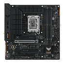
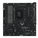
Back in October of last year, pictures from an ASUS event in China appeared online, showing off a pair of mATX motherboards that had most of its peripheral and power connectors on the reverse side of the motherboard. Now it appears that ASUS has decided to launch such a product, in the shape of the unforgettably named TUF Gaming B760M-BTF WiFi D4. The BTF part in the model name stands Back To (the) Future, although ASUS is most likely not allowed to use that term due to copyright restrictions, so it had to make do with BTF. Regardless of naming, the interesting part here is that all of the power connectors, the four SATA ports, the USB-C and USB 3.0 headers, as well as multiple other headers and one of three M.2 slots, are on the reverse side of the motherboard. This is all done to allow for cleaner cable management.

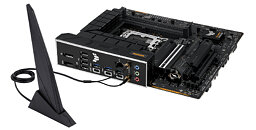
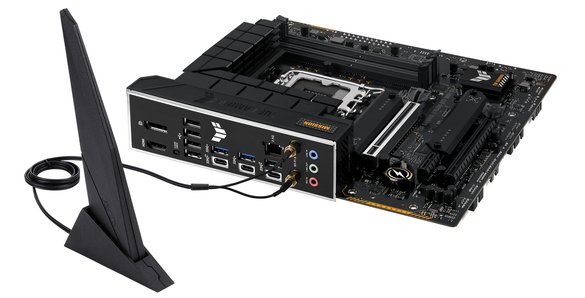
Other noteworthy features on the board include a single PCIe 5.0 x16 slot, one PCIe 4.0 x4 and one x1 slot, three USB-C ports, of which one is capable of 20 Gbps speeds and 2.5 Gbps Ethernet. As this is a mid-range board, we presume ASUS wants to test the waters so to speak, to make sure there's a market for such a product. However, one major hurdle is the small fact that there aren't any suitable chassis in the market and the product page even mentions that "This motherboard is compatible with specific case models", without going into any details. Presumably, ASUS will offer a suitable chassis, or have some partner(s) lined up that will provide a suitable chassis. Gigabyte announced something similar in May last year, but decided to team up with system integrators, something ASUS might be planning on as well.


View at TechPowerUp Main Site | Source
 
How exactly are you supposed to connect anything there with the board screwed into the case? Am I missing something?
 
Very interesting. I wonder if it fits every case in terms of cutouts. It would be a shame to find out the hard way that a solid case panel is blocking the way to the ATX power plug, for example.

Also, what's with the "MISSION" logo near the VRM heatsink? Or am I the only one who hates pointless text on things? It would be a nice-looking board otherwise.
 
How exactly are you supposed to connect anything there with the board screwed into the case? Am I missing something?
See the link to the Gigabyte news post and you'll see how it's done if you watch the video. Requires a suitable case.

Very interesting. I wonder if it fits every case in terms of cutouts. It would be a shame to find out the hard way that a solid case panel is blocking the way to the ATX power plug, for example.
See above answer.
 
thats not the bottom but the reverse ...
those are two different things
(okay, they're at the bottom and on the reverse, but headers being on the bottom is hardly a revolutionary thing. they've been there for many a decade now.)
 
thats not the bottom but the reverse ...
those are two different things
(okay, they're at the bottom and on the reverse, but headers being on the bottom is hardly a revolutionary thing. they've been there for many a decade now.)
Happy now?
 
See the link to the Gigabyte news post and you'll see how it's done if you watch the video. Requires a suitable case.
Wow! This looks absolutely awesome! :) On the downside, I can see lots of RMA requests from people who didn't check for case compatibility and/or were unaware of the connectors' odd location.

There needs to be a standard around this. When there is, I'm all in!
 
See the link to the Gigabyte news post and you'll see how it's done if you watch the video. Requires a suitable case.
Yeah, I see, it requires special cases. This is stupid and against standards, I hope it won't become a thing. There are many easier way to hide the cables going down there, I could hide them nearly completely on both the front AND the back of the case, in my Antec P183 from 2009.
 
Yeah, I see, it requires special cases. This is stupid and against standards, I hope it won't become a thing. There are many easier way to hide the cables going down there, I could hide them nearly completely on both the front AND the back of the case, in my Antec P183 from 2009.
I don't mind if it becomes a thing, but Asus and Gigabyte have done it differently, which is even less acceptable.
If this is to become a thing, it has to be a new standard, or it'll just be a mess.
 
Wouldn't it have been a better approach for Gigabyte to create a case with an adjustable shroud that can cover up these cables along the motherboard's edge?

This seems like the worst way you could have tried to hide the cable as it requires a specific case.
 
I don't mind if it becomes a thing, but Asus and Gigabyte have done it differently, which is even less acceptable.
If this is to become a thing, it has to be a new standard, or it'll just be a mess.

Basically.

Two simple design changes and it works in practically every case already in use with minimal or no alterations:

1) Add a few mm to gap standoff creates between case and board.
2) Revisit a non-standard Asus design which rotated this set of connectors 90 degrees so cables run horizontally off the board instead of projecting outwards.
 
I certainly did not think of Steven Spielberg's Trilogy when I read the name.
Maybe they'll do a custom UEFI for it and call it UTI while they're at it. Totally means Ultimate Technician trouble-free Interface, totally...
:kookoo:

We get all kinds of products with 0 Fooks given about their names or perceptions.
Seriously, I cannot browse Amazon w/o running across brand and product names that'd never be used by an English-first speaking company.


Now if we could STOP putting the GPU cable right IN THE MIDDLE of the effin card that would be great.
Here, I thought I was the only one that thought that was dumb as hell.
 
Amount of recent product releases with solutions in search of problems is too damn high. Sign of market maturity.
 
Basically.

Two simple design changes and it works in practically every case already in use with minimal or no alterations:

1) Add a few mm to gap standoff creates between case and board.
How is that supposed to work, especially with regards to the rear I/O?
2) Revisit a non-standard Asus design which rotated this set of connectors 90 degrees so cables run horizontally off the board instead of projecting outwards.
Use cables with an L-shaped connector?
 
Asus, if you are going to make a special edition motherboard for specialty builds - make it Z790 and DDR5. It only makes sense.
 
Hi,
Seems pretty stupid to put onboard graphics that high but then again onboard graphic's on a desktop seems pretty stupid to in 2023 :laugh:

Wifi antennas lower lower, well we all know antennas work better as low as possible :kookoo:

Guess this board really needs an upside down sinners case :cool:
 
How is that supposed to work, especially with regards to the rear I/O?

Insert coffee and nutrition, then post.

It doesn't. :oops:

Use cables with an L-shaped connector?

No, same layout as Maximus XI Gene headers along the bottom + unstacking SATA, etc.

My explanation for extending the gap above directly relates to thickness of COM port when laid on its side exceeding gap between mobo and case per spec. IF this design gained traction my answer would be to just dremel a full length cable thickness slit with discretely placed rectangular hole for connectors to enter through exactly where the COM port was.


Maximus XI Gene.jpg
 
Last edited:
If there is more support from all mobo manufacturers and case makers, it could be a small win for cable management.
The problem here is that it's in the wrong location. It's at the bottom meaning other form factor sizes like even ATX will be lower down, making the reverse holes in the case harder to do in multiple locations. Ths is of course surmising that ATX won't have the reverse connectors in the middle of its layout? It's a shame it's not at the top on the backwards side for easier compatibility?
 
Hopefully the cases that support this will be decent and not too hard to find.
 
There will be a shortage of Drimal tools.
And the needed depth on the back side of the motherboard.
 
Last edited:
How is that supposed to work, especially with regards to the rear I/O?
Insert coffee and nutrition, then post.

It doesn't. :oops:

No no, hear me out, put the IO panel on the back of the board raising the board about 5 cm away from the case


I'm all for options in the market, why not right?, but I find this pretty dumb. for the sake of hiding cables - why? is it better to look at a bare pcb? you either fine with looking at it or can always go with a solid sidepanel - they're making something that will require a specific case and be more expensive to produce (both due to lower volumes and by needing to pass 2 times through the smt line to place the components on the back). A solution looking for a problem that isn't there, oh well.
 
Back
Top