• Welcome to TechPowerUp Forums, Guest! Please check out our forum guidelines for info related to our community.

So you want PWM control of your new CPU fan?

pvillegeek

New Member
Joined
May 16, 2010
Messages
1 (0.00/day)
Better late than never

It looks like I'm a little late to this party, but seeing your schematic made be cringe!

I guess I should start off by mentioning that I am an electrical engineer, so I know what I'm talking about.

What's right:
On the positive side, you did keep ground as ground, and you chopped the 12v line (I've seen several attempts messing this up). If you chop the ground wire it will mess up the tach output. Other than that I'm surprised this circuit works at all.

What's wrong:
The PWM pin on the motherboard is designed to sink up to 5.25v, in your circuit it gets up to 12v! (though due to the resisters it can't draw much current, so probably won't damage anything)

The voltage to the base of the transistor is switching between 12v (on) to 6v (off) so it SHOULDN'T ever be turning off! If it is in fact working it's only because the transistor you chose has a very high base current.

Oh, and varying the resistor will NOT change the minimum speed of the fan. It will have no positive effect on the circuit, and might make the circuit (if it works now?) stop working completely.

How to fix it:
The PWM input should be connected directly to the base of the transistor between the resistor pair. And the bottom of the resistor pair should be connected to ground (not PWM).
Finally you should change the resistor values to: 3.9k between pwr and the base of the transistor, and 2.4k between the base of the transistor to ground. This will allow a higher current to the base of the transistor, making it more likely that you'll be in the switching region of the transistor, rather than the analog region.

Hope someone finds this useful
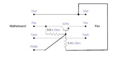
wellactually.jpg
 
Last edited:
Joined
Feb 24, 2009
Messages
3,516 (0.61/day)
System Name Money Hole
Processor Core i7 970
Motherboard Asus P6T6 WS Revolution
Cooling Noctua UH-D14
Memory 2133Mhz 12GB (3x4GB) Mushkin 998991
Video Card(s) Sapphire Tri-X OC R9 290X
Storage Samsung 1TB 850 Evo
Display(s) 3x Acer KG240A 144hz
Case CM HAF 932
Audio Device(s) ADI (onboard)
Power Supply Enermax Revolution 85+ 1050w
Mouse Logitech G602
Keyboard Logitech G710+
Software Windows 10 Professional x64
Are the wires and signals the same coming off a video card?

Thinking about doing what Zalman should have done and make my VF3000a a pwm version.
 
Joined
Jan 6, 2007
Messages
2,555 (0.39/day)
Location
Illinois
Processor i7 2600k@4.6ghz
Motherboard MSI z68ma-ed55
Cooling Silentx Extreem 120mm
Memory 2x4gb XMS 7-8-7-20 1600
Video Card(s) HD6870
Storage 2x128gb Kingston Hyper-X (Raid0), 2x750gb RE3 (RAID1), 2x750gb RE3 (RAID1)
Display(s) Soyo 24", Gateway 22"
Case Fractal Design Arc Mini 6x120mm fans.
Audio Device(s) Onboard
Power Supply Zalman 750w
Software Windows 7
Hope this isn't too old to post.

I made another version. It provides 5v pull-up on the PWM (It was suggested. I don't know why this is needed. Motherboard detection of PWM fan installed maybe.) and kick start on power-up to get stopped fans moving. It also has a minimum speed adjustment to compensate a wider varity of fans. Roughly 4~10v or something like that. I used a PNP as a high side switch. Seemed more efficient to use the PNP plus the ground is maintained so the tach works right.

It works in the emulator but hasn't been bench tested. Lets pick it apart!

4 to 3 pin PWM adaptor.JPG


Here is a scope shot of the power-up kick and switching between full-low and full-high speed.

4-pin_scope.JPG


It looks like I'm a little late to this party, but seeing your schematic made be cringe!

I guess I should start off by mentioning that I am an electrical engineer, so I know what I'm talking about.

What's right:
On the positive side, you did keep ground as ground, and you chopped the 12v line (I've seen several attempts messing this up). If you chop the ground wire it will mess up the tach output. Other than that I'm surprised this circuit works at all.

What's wrong:
The PWM pin on the motherboard is designed to sink up to 5.25v, in your circuit it gets up to 12v! (though due to the resisters it can't draw much current, so probably won't damage anything)

The voltage to the base of the transistor is switching between 12v (on) to 6v (off) so it SHOULDN'T ever be turning off! If it is in fact working it's only because the transistor you chose has a very high base current.

Oh, and varying the resistor will NOT change the minimum speed of the fan. It will have no positive effect on the circuit, and might make the circuit (if it works now?) stop working completely.

How to fix it:
The PWM input should be connected directly to the base of the transistor between the resistor pair. And the bottom of the resistor pair should be connected to ground (not PWM).
Finally you should change the resistor values to: 3.9k between pwr and the base of the transistor, and 2.4k between the base of the transistor to ground. This will allow a higher current to the base of the transistor, making it more likely that you'll be in the switching region of the transistor, rather than the analog region.

Hope someone finds this useful
View attachment 35575

I forgot to comment on this. The reason I used 2 10k resistors was so the motherboard could NOT stop the fan. The base voltage will alternate between roughly 12 and 6 making full/half speed. This is also why adjusting the resistor will effect the minimum speed. I'm not very informed on Intel's PWM specs but I do know that grounding the PWM pin of a PWM fan will NOT stop the fan. It only reduces the speed.

In your revision, should the motherboard sink the base 100% when it calls for low speed, your modified version will allow the fan to COMPLETELY stop. We don't want this and I don't recomend your revision to anyone for that reason alone. My 10k off 12v is only 1.2ma of current for the board to sink. I don't see a problem here. With your 3.9k the board has to sink about 3.1ma. Almost 3x more then my original design. I'm sure a board can sink 3.1ma anyways but it's not necessary. Just use a transistor with high gain and a 1.2ma is plenty of base drive.
My original schematic works fine if you see my intentions. It's cheap, easy, safe, and more people could handle soldering a few components directly to themselfs vs. building a more advanced circuit on a PCB.
 
Last edited:
Joined
Feb 24, 2009
Messages
3,516 (0.61/day)
System Name Money Hole
Processor Core i7 970
Motherboard Asus P6T6 WS Revolution
Cooling Noctua UH-D14
Memory 2133Mhz 12GB (3x4GB) Mushkin 998991
Video Card(s) Sapphire Tri-X OC R9 290X
Storage Samsung 1TB 850 Evo
Display(s) 3x Acer KG240A 144hz
Case CM HAF 932
Audio Device(s) ADI (onboard)
Power Supply Enermax Revolution 85+ 1050w
Mouse Logitech G602
Keyboard Logitech G710+
Software Windows 10 Professional x64
The design pvillegeek gives lets you basically make any 3 pin fan a 4 pin pwm fan. Since you always receive a signal to the base even when it sinks it 100%, the transistor will always be switching between 12v and 0v and never go to a constant 0.0v being supplied.

You don't need a pcb either to build it. I should have some free time this weekend (hopefully) so I should be able to get one put together.
 
Joined
Jan 6, 2007
Messages
2,555 (0.39/day)
Location
Illinois
Processor i7 2600k@4.6ghz
Motherboard MSI z68ma-ed55
Cooling Silentx Extreem 120mm
Memory 2x4gb XMS 7-8-7-20 1600
Video Card(s) HD6870
Storage 2x128gb Kingston Hyper-X (Raid0), 2x750gb RE3 (RAID1), 2x750gb RE3 (RAID1)
Display(s) Soyo 24", Gateway 22"
Case Fractal Design Arc Mini 6x120mm fans.
Audio Device(s) Onboard
Power Supply Zalman 750w
Software Windows 7
The design pvillegeek gives lets you basically make any 3 pin fan a 4 pin pwm fan. Since you always receive a signal to the base even when it sinks it 100%, the transistor will always be switching between 12v and 0v and never go to a constant 0.0v being supplied.

You don't need a pcb either to build it. I should have some free time this weekend (hopefully) so I should be able to get one put together.

My point was you don't want the fan to go to zero and I designed it that way by letting the PWM switch the low side of a voltage divider. Is anyone reading? :rolleyes: pvillegeek's design will work much better (as a 12-0 switch) if you get rid of the 2.4k. If not, your fan isn't going to be spinning as fast as it could be so heads up. Most fan's are going to have a hard time starting with pvillegeek's changes so WATCH THE FAN the first time you use it. It may hardly spin at all. His circuit only give the fan 4~5v MAX. DO NOT BUILD IT! I had it right the first time and an "electrical engineer" he should have seen what my intention was with the circuit. If you wan't, swap out both 10k resistors (in my design) with 4.7k if your transistor is low gain. At least the fan won't stall with my original design.
 
Last edited:
Joined
Feb 24, 2009
Messages
3,516 (0.61/day)
System Name Money Hole
Processor Core i7 970
Motherboard Asus P6T6 WS Revolution
Cooling Noctua UH-D14
Memory 2133Mhz 12GB (3x4GB) Mushkin 998991
Video Card(s) Sapphire Tri-X OC R9 290X
Storage Samsung 1TB 850 Evo
Display(s) 3x Acer KG240A 144hz
Case CM HAF 932
Audio Device(s) ADI (onboard)
Power Supply Enermax Revolution 85+ 1050w
Mouse Logitech G602
Keyboard Logitech G710+
Software Windows 10 Professional x64
Intel spec for the 4 pin pwm circuit states that at startup there be a 100% duty cycle signal sent on the pwm pin. As such I don't see how there could be a problem with a fan not being able to spin up.

As for the electrical engineering part, I've got pvillegeek and another one (other then myself) saying pvillegeek's design will work. So I'll take my chances.
 

NGinuity

New Member
Joined
Jan 2, 2012
Messages
3 (0.00/day)
Just brainstorming for fun here, found this thread via Google....

I realize this thread is long since dead but I was wondering why are you fussing with the BJT when something like an N-Channel FET or similar could drive this without the complication. Is there a particular reason why you went this way? Couldn't you just send the PWM signal straight to the gate of a FET? The PWM signal is likely quite adequate to saturate the FET to full on (most decent ones I see are full on above 4 volts), which is what you want during the high of the duty cycle anyway. The IRFZ46N immediately comes to mind, albeit extremely overkill, and the switching frequency of 25kHz, no sweat. Maybe the IRFZ24N, cheaper, but still a bit overkill. Another thing it could possibly buy you is controlling more than one fan off of the same source pin.....the only problem is that you'd only get tach from one fan in that configuration.
 
Last edited:
Joined
Jan 6, 2007
Messages
2,555 (0.39/day)
Location
Illinois
Processor i7 2600k@4.6ghz
Motherboard MSI z68ma-ed55
Cooling Silentx Extreem 120mm
Memory 2x4gb XMS 7-8-7-20 1600
Video Card(s) HD6870
Storage 2x128gb Kingston Hyper-X (Raid0), 2x750gb RE3 (RAID1), 2x750gb RE3 (RAID1)
Display(s) Soyo 24", Gateway 22"
Case Fractal Design Arc Mini 6x120mm fans.
Audio Device(s) Onboard
Power Supply Zalman 750w
Software Windows 7
No problem from me with bumping an old thread. Knowledge is power?

Using an N-ch mosfet, you will likely be switching the low side (neg) of the fan. This pin is also used for the tach circuit (return path) and switching it could (will) cause problems with the tach readings. If you are not using the tach you could switch the low side but Intel PWM spec is an on/off "PWM" signal. (It's not actually PWM until you plug the fan in.**) Most N-ch mosfets require at least 8v to the gate. You could use a logic-level mosfet which will accept a 5v signal on the gate but this still leaves the tach issue.

Intel's PWM spec states a minimum fan speed of 30%. This is easy to do with a transistor by feeding a current to the transistors base while the PWM is in it's min. state (0v). Intel spec also calls for a start-up pulse to kick the fan into rotation from a stop. You can't simply apply 30% voltage to a stopped fan and expect it to start 100% of the time. Some motherboards will power-up with 100% PWM to start the fan but my understanding is this isn't a requirement of the board manufacturer.

The circuit was simple and cheap but may need tweaking to work with your particular choice of transistor and fan. It was provided as an example of how you could take advantage of the PWM function without the complex circuitry needed to be 100% "Intel compliant".

Hope this helps.

mastrdrver - I didn't see your post. Your wrong. Pvillegeek's modification will not work correctly. The PWM signal toggles between open and closed. It is not providing 0 and 5v or anything else. It's only opening and closing a path to ground. Imagine the PWM signal is in it's is open state (100%). He has 3.9k and 2.4k dividing 12v to the base of the transistor which is 4.565v. This will not give you full power to the transistor or the fan. When the PWM signal is closed, the base is grounded giving 0v to the fan. He circuit will toggle the fan voltage between 0 and (guessing) 4v. It may not spin the fan AT ALL.

In my original circuit, if the PWM is open (100%), the transistor's base recieves power (12v) via. the 10k from pwr to base (call it R1). When the PWM is grounded, the other 10k (R2) create a resistor divider that esentially gets you ~6v at the base. This toggles the base between ~6v and 12v. Any exact calculation require knowing the specs of the transistor being used. I do NOT recomend using Pvillegeek's modifications.

Transistors are current devices and there's alot more to calculating "in vs. out" voltages, or rather currents, like knowing the transistor's specs and the current of the fan. To visually understand how the transistor works in a perfect world, you can imagine 5v at the base gives you 5v out. It's more like 5v in gets you 4-4.5v out but you get the idea. With Pvillegeek's modification, the base will -never- see more then 4.565v which can NOT drive the transistor into full conduction even in a perfect world.

See post #28.
 
Last edited:
Joined
Feb 19, 2009
Messages
1,869 (0.32/day)
Location
UK Warwickshire
System Name PC-Chips
Processor AMD Ryzen 7 5700x3D
Motherboard Asus ROG Strix B550-F Gaming.
Cooling Thermalright Peerless Assassin 120 SE.
Memory Patriot Viper 32gig dual channel 3600mhz
Video Card(s) PowerColor HellHound RX 7900 GRE OC
Storage 2 Samsung 860 EVO's 500gig / 2TB crucial P3-NVME / WD-BLUE SN550 1TB M.2 / SP A55 512gig / 8TB HDD
Display(s) TCL 50-inch 4k TV freesync HDR
Case Modded NZXT H510
Audio Device(s) Realtek S1220A - Yamaha A-S501 AMP - Wharfedale diamond 9.1 speakers - Wharfedale SW150 sub
Power Supply EVGA SuperNOVA G6 750W 80+ Gold
Mouse Some cheap wireless thing
Keyboard Razer Cynosa lite
VR HMD Oculus Quest 2 128gig version
Software Windows 11 pro 64bit
Some motherboards will power-up with 100% PWM to start the fan but my understanding is this isn't a requirement of the board manufacturer

My motherboard does this, Fan kicks it at full speed then settles down.

Some great info in this thread to its very intresting to read.
 
Joined
Jan 6, 2007
Messages
2,555 (0.39/day)
Location
Illinois
Processor i7 2600k@4.6ghz
Motherboard MSI z68ma-ed55
Cooling Silentx Extreem 120mm
Memory 2x4gb XMS 7-8-7-20 1600
Video Card(s) HD6870
Storage 2x128gb Kingston Hyper-X (Raid0), 2x750gb RE3 (RAID1), 2x750gb RE3 (RAID1)
Display(s) Soyo 24", Gateway 22"
Case Fractal Design Arc Mini 6x120mm fans.
Audio Device(s) Onboard
Power Supply Zalman 750w
Software Windows 7
Post 33 was edited to add some more information to be found here.

**A PWM signal would be a signal that alternates between high and low states and the duration of both states totals 100%.

If it's on 1/2 the time, and off the other half, it is a 50% duty cycle or 50% PWM. Since the PWM pin does not actually supply

a voltage there is no "signal" present on the pin until you plug in the fan. The control circuitry in the fan itself provides a

very low current 5v signal which is grounded out by the motherboard via the PWM pin. The fan circuitry needs to read the

voltage alternating between 0 and 5v and adjust the fan speed accordingly. The PWM frequency (or width) to the fan's motor

itself could be completely different then the PWM frequency the motherboard is switching at. When the board calls for 50% fan

speed, it sets the PWM duty cycle to 50%. The actual motor's speed in the fan is seldom linearly proportionate to duty cycle.

50% duty cycle to a motor may not reduce the speed by 50%. It might reduce the speed by say 30%. How do you fix this? The fan

circuitry gives the motor whatever duty cycle it needs to adjust it's speed to be linearly proportinate to the motherboard's

request. Placing all of this control circuitry in the fan itself eliminated the motherboard manufactures from having to deal

with it. Since fan motors vary greatly in their power requirements and designs, it's neither possibile nor cost effective to

create a "one size fits all" control circuitry on the motherboard. It's up to the fan designer to decide what their particular

fan may need as far as the electronics are concerned.


Even more about PWM...

I mentioned the frequency to a (quality) fan motor (stator) can be higher then the frequency at the PWM pin. This is to reduce

or eliminate noise emitted from the motor. The motor can act just like a speaker and may vibrate at the same rate as the duty

cycle. Because of this, the switching frequency is set high enough that it can not be heard. Every put a cheap fan on a Zotac

motherboard and heard it buzzing? ;)


A little more about how PWM works...

Imagine a standard tungsten filament light bulb in a fixture on the ceiling. There is a switch on the wall to control the

light. If you slowly turn the switch on and off the light will simply turn on and off. There is actually a slight delay in the

time it takes the light to turn on or off because the filament takes time to heat and cool. If you turn the switch on and off

faster then the filament can -fully- heat or cool, it will look dim and not flicker at all. This speed is the switching

frequency of the pulses. If the switch is on half of the time and off half the time the light will dim to 50%. This is the duty

cycle. The duty cycle is a length of time also called pulse width. To adjust this time is to modulate it. Pulse Width

Modulation aka. PWM.


And even more about switching and motor control...

Like the filament in a light, a motor takes time to spin up or down. If the switching frequency is too low, the motor will have

time to slow down, or spin up, faster then we want it to. If we choose a switching frequency that is faster then the time it

takes for the motor to spin up or down, the motor's speed will stay smooth. This frequency still needs to be higher then just

smoothing the motor's speed. The magnetic field can still fluctuate greatly and produce noise. Ever hear the whine in a

cordless drill when you pull the trigger slightly? This is because the switching frequency is not high enough to be inaudable.

Well why not? Mosfets are wonderful little switches because when they are completely on, their resistance is VERY low. This

makes them a great choice where high currents need to be controlled by a small device. Mosfets used in applications like this

typically have 3 leads. Gate, Drain, and Source. Without going into great detail, think of the 3 leads as in, out, and control.

The gate is the control and I'll put a little focus on that. The Mosfet has a delay when it turns on. Say the gate is a knob on

a faucet. Turn the knob on and the water flows and visa-versa. Turn the knob quickly on and off and you are modulating the flow

of water, but, it takes time for you to open and close the valve. A mosfet has the same problem. When the mosfet is changing

states on or off it has higher resistance. This creates heat. Not good. So, the switching frequency has to be fast enough that

the magnetic fields don't have time to fully build or colapse (to reduce noise) but not to high or the mosfet will be

opperating in it's "linear region" where resistance is higher. This is called swithcing loss. In the cordless drill, a single

mosfet can control 100 amps of current. Impressive. To help keep it cool, a low switching frequency was chose to minimize

switching losses and heat generated by those losses yet high enough to keep the motor running smoothly. Noise is not an issue with a cordless drill so there's no need to keep it quiet.


Switching and a computer's processor supply.

This information also applys to a switching power supply or switching regulator. Have you seen the newer boards that have a v-reg switching frequency option? Typically 250khz or so. A higher frequency gives better, smoother regulation, as explained above, but at a cost. More heat is generated by the mosfets due to switching losses. If you can keep your mosfets cooler, higher is better. If your not overclocking and your system is stable at a lower switching frequency, then reduce it to lower the amount of heat generated. See those little inductors around your CPU socket? Also called chokes or toroids. These help smooth and average the pulses of the mosfets and do so using a small magnetic field. It's a little more complicated then that but that's the just of it. If you really need to know how they work, just ask.

Hopefully this gives a better understanding to how PWM and mosfets work. :)

EDIT- I have no idea why everythying is double spaced. Sorry about that.
 
Last edited:

NGinuity

New Member
Joined
Jan 2, 2012
Messages
3 (0.00/day)
Using an N-ch mosfet, you will likely be switching the low side (neg) of the fan. This pin is also used for the tach circuit (return path) and switching it could (will) cause problems with the tach readings.
Couldn't this be easily mitigated by running it through a RC filter and a comparator as a Schmitt Trigger to "rebuild" the pulses? The RC filter would take out the PWM trash relative to correct ground, leave the tach pulses, and then feed those into + on the Schmitt Trigger, 5VDC on - of the Schmitt Trigger (non-inverting), and clean them up for return to the computer. This is not needed if the tach circuit on the mobo has a Schmitt trigger input, but there's no harm in using it if it doesn't.

If you are not using the tach you could switch the low side but Intel PWM spec is an on/off "PWM" signal. (It's not actually PWM until you plug the fan in.**) Most N-ch mosfets require at least 8v to the gate. You could use a logic-level mosfet which will accept a 5v signal on the gate but this still leaves the tach issue.

The MOSFET models I described both require only 4 volts to the gate to saturate I believe.

Intel's PWM spec states a minimum fan speed of 30%. This is easy to do with a transistor by feeding a current to the transistors base while the PWM is in it's min. state (0v). Intel spec also calls for a start-up pulse to kick the fan into rotation from a stop. You can't simply apply 30% voltage to a stopped fan and expect it to start 100% of the time. Some motherboards will power-up with 100% PWM to start the fan but my understanding is this isn't a requirement of the board manufacturer.
But you're not talking about 30% voltage. You're talking about 100% voltage at a 30% duty cycle for every pulse (big difference), give or take a little to compensate for rise/fall slew. 30% voltage would mean you're only powering the fan with 4 volts, but when the PWM signal pulses the gate, you're applying 12 volts from source as long as the gate is open all the way (it would be). Each pulse will fully saturate the gate of the FET regardless of it's duty cycle (Current flow is also not restricted because the gate is saturated). The real question is, can it spin up at a 30% duty cycle on it's own (not sure why not unless the fan bearings are causing too much friction)? Would be an interesting experiment to play with. Perhaps I can breadboard some flavor of PWM generator with the stuff in my junkbox. We're only talking about a very loose 25KHz generator here, and I can probably use the old 555 timer with 2 diode and potentiometer trick to modulate the PWM duty cycle. Although to accurately simulate the problem, I'd need to sink the signal instead of generate it. Not a big deal though. Would also give me some time to look at the tach wire output problem.

mastrdrver - I didn't see your post. Your wrong. Pvillegeek's modification will not work correctly. The PWM signal toggles between open and closed. It is not providing 0 and 5v or anything else. It's only opening and closing a path to ground. Imagine the PWM signal is in it's is open state (100%). He has 3.9k and 2.4k dividing 12v to the base of the transistor which is 4.565v. This will not give you full power to the transistor or the fan. When the PWM signal is closed, the base is grounded giving 0v to the fan. He circuit will toggle the fan voltage between 0 and (guessing) 4v. It may not spin the fan AT ALL.

Well, that's actually only part of it. The 4 volts to the base would be just fine if there's enough current supplied to it as well to bias it. This is provided that the PWM sink on the MOBO finds 4 volts valid which shouldn't be an issue, but with a MAXIMUM capability of 5.65 volts, I'd find it hard to believe that 4 wouldn't work considering modern day TTL logic is around 3.3 volts.

The missing part of the equation is the load current on the collector side of the transmitter. As long as the transistors base is in saturation with respect to the load, the fan voltage will be around 12 volts, not 4.

Keep in mind the following equation:
RB = (VS * hFE)/(5 * lc)
Where RB is Base resistance, VS is base supply voltage, hFE is transistor beta (ideal), and lc is load current in amps. The "5" constant is derating the load current for tolerance considerations (assuring trouble free operation by overating the load). I'm also haphazardly assuming 0 volts between Base and Emitter, but the design constraints aren't that tight and that voltage drop is negligible. Should be ok. The load current derating should more than make up for this.

If we use a cockroach 2N3904 (not a good choice for PWM but will satisfy the explanation and some may choose it who don't know about the downfalls of them), it has a generally excepted ideal beta of 100 in accordance with prophecy.

The tricky part is sizing the actual load current consumption. Each fan is different (which is also where using a BJT becomes kind of iffy). My Nexus fans each run .15 amp according to spec. If we take that and do a little bit of math (!!!!!), we get the resulting equation:
RB = (4 volts * 100)/(5 * .15)
RB = 400 / .75
RB ~ 533 ohms (ideal theoretical full saturation)

So now we know what it "should" be to drive it into saturation, we see using Ohms law that we end up needing a current of 7 milliamps (4 volts / 533 ohms = .007 amps). In pvillegeek's schematic, he's supplying a current of only 1 milliamp (4 volts /2400 ohms) to the base, which may cause the transistor to not fully bias, meaning the load current of .15 in my fan will not be 100% no matter the duty cycle, even if the derated constant were taken out. But that's why the fan theoretically won't spin, not because of the voltage. For what it's worth though, it would likely work in the transistors analog region pretty well. He was on the right track when he suggested using the 3.9k/2.4k pair instead of the 10k to properly bias the base into the switching region and bring down the voltage on the base to a safe level for the MOBO per Intel specs. Replacing the BJT with a FET in his schematic might work just fine to drive the fan, but I'd like to see a little more wiggle room over 4 volts to bias the gate over the FET, just in case.

In my original circuit, if the PWM is open (100%), the transistor's base recieves power (12v) via. the 10k from pwr to base (call it R1). When the PWM is grounded, the other 10k (R2) create a resistor divider that esentially gets you ~6v at the base. This toggles the base between ~6v and 12v. Any exact calculation require knowing the specs of the transistor being used. I do NOT recomend using Pvillegeek's modifications.

Voltage does not bias the base of a BJT, current does. (Well, actually, that's not totally true from a physics standpoint but generally accepted that way by EE's, more accurately voltage ALONE doesn't because it's actually the causal relationship of voltage to current :-D). Toggling between 6 volts and 12 volts on your base is immaterial if your resistor is sized improperly and all that is really happening is a current fluctuation relative to that (I = V/R with constant resistance). You're still getting 12 volts on the fan nonetheless. The current to the fan, not the voltage, is what fluctuates, causing the fan to slow, but your voltage difference on the base can be whatever you want as long as it's within spec of the transistor, and the resistor that derives the current to the base is proper. In the case of your schematic, the spec says that the sink is only rated to 5.65 volts MAXIMUM. You're overvolting the PWM signal back to the computer. Your SPICE simulation confirms that as well. That line at the bottom of the fall should be dead on zero with respect to ground, not around 6 because the computer should sink every bit of it.

Transistors are current devices and there's alot more to calculating "in vs. out" voltages, or rather currents, like knowing the transistor's specs and the current of the fan. To visually understand how the transistor works in a perfect world, you can imagine 5v at the base gives you 5v out. It's more like 5v in gets you 4-4.5v out but you get the idea. With Pvillegeek's modification, the base will -never- see more then 4.565v which can NOT drive the transistor into full conduction even in a perfect world.

Actually 5 volts at your base doesn't mean you get 5 volts out (taking out the voltage drop). This is only true if your source voltage is 5 volts as well, which it isn't. Source voltage to the collector is what does that. If this were not true, for example, you could not use a BJT on a 5 volt microcontroller output to drive a 12 volt load that actuates a 12 volt relay ('cause the relay no workie under 12 volts). The problem with using BJT's (as you have hinted to in your response, and I've shown above) is that you have to recalculate your base resistor value for every additional load you place on the collector side. If you undersize the base resistor to accommodate a "maximum load" scenario for multiple fans, running only one fan will generate excess current (although you prevent damage to the transistor by staying within design specs of it). If you oversize the base resistor, you run the risk of not supplying enough current to the gate to bias it open. I'm not disagreeing that it could be done this way at all, I'm just saying using a FET seems a little more efficient from a consumption perspective, are pretty much agnostic to current load considerations, and they seem to be a lot more "switching tolerant" than BJT's as well.

I know a lot of what I mentioned would add slightly to the cost, but the reliability would be great if made to work. Either way, great exercise in all regards to get me away from just doing circuit board rework on the bench. I currently have 3 fans running at full tilt and it's getting into my mic audio. It's a real shame I have to touch the noise gate console JUST for that. Cheers!
 
Joined
Jan 6, 2007
Messages
2,555 (0.39/day)
Location
Illinois
Processor i7 2600k@4.6ghz
Motherboard MSI z68ma-ed55
Cooling Silentx Extreem 120mm
Memory 2x4gb XMS 7-8-7-20 1600
Video Card(s) HD6870
Storage 2x128gb Kingston Hyper-X (Raid0), 2x750gb RE3 (RAID1), 2x750gb RE3 (RAID1)
Display(s) Soyo 24", Gateway 22"
Case Fractal Design Arc Mini 6x120mm fans.
Audio Device(s) Onboard
Power Supply Zalman 750w
Software Windows 7
You need to READ my words sir. Your arguing alot of things as if I stated them as solid facts. I'm not trying to explain things to electrical engineers.

I said "It's more like 5v in gets you 4-4.5v out but you get the idea."

You say "Actually 5 volts at your base doesn't mean you get 5 volts out"

I said "Any exact calculation require knowing the specs of the transistor being used." and also "Transistors are current devices and there's alot more to calculating "in vs. out" voltages"

I thought I cleared everything up didn't I? Stop trolling for an intelectual argument. That's beyond the scope of this thread. My intention was to provide the simplest most inexpensive solution to control a 3pin fan off a 4pin header. It works, I use it, and it won't harm anything. It can also be soldered together lead to lead and shrink-wraped inline with the wires. Is it perfect? Of course not. That would require using predetermined components and more of them. This adds to the cost and complexity. Your more then welcome to offer your own circuit.
 
Last edited:

NGinuity

New Member
Joined
Jan 2, 2012
Messages
3 (0.00/day)
You need to READ my words sir. Your arguing alot of things as if I stated them as solid facts. I'm not trying to explain things to electrical engineers.
I mean no ill intention towards you, but I did respond because you didn't clear everything up. I am simply pointing out the problems as I see in your posted schematic that I see as an unsafe design. On the contrary, I think my response was more than adequate in the civility department. My advice costs you the same as your advice costs me. Take it for what it is.

I said "It's more like 5v in gets you 4-4.5v out but you get the idea."

You say "Actually 5 volts at your base doesn't mean you get 5 volts out"
With all due respect, you really should reread what I wrote before you call me out on it. It wasn't an intellectual reply. 5 volts at the base does not mean you get 5 volts output when you've got a 12 volt supply on the collector. It doesn't mean you get "4-4.5v" either. It means you get around 12 on the fan when the gate is saturated.

I said "Any exact calculation require knowing the specs of the transistor being used." and also "Transistors are current devices and there's alot more to calculating "in vs. out" voltages"

My calculations were hardly "exact". More "ballpark", but these are things you need to know when you want to do these designs properly. I gave you the extremely stripped down, condensed version at that.

I thought I cleared everything up didn't I? Stop trolling for an intelectual argument. That wasn't the purpose of this thread.

Who's trolling? I understand that you are very defensive of your design (believe me, I understand any circuit designer doing that), but my intention was not to just tell you "you're wrong" like others have done, but to show you, and others with come to this page with no previous experience WHY some of the things you did are an unsafe design (such as overvolting your PWM pin, for instance) so that you can actually apply some of it and not make the same mistake again. Additionally, if you feel I'm wrong, tell me why, but don't attribute valid discussion as "trolling". I have ZERO problem with you finding flaw in something I have said and up until this point you did an excellent job citing your design reasons of why you chose the BJT over the FET. I have no desire to get into a virtual slap fight with you and I think some of your criticism is a little harsh toward others, especially when you had an initial outlook of "Knowledge is power" toward me. It's a two way street you know. If you're not going to be receptive to feedback, don't put yourself out there.

So, that being said, if you are not going to take feedback on your design, what IS the purpose of this thread? You've driven off two other people who obviously are very competent in this area because they've been trying to explain to you why things in your design are unsafe, things I agree with and can explain mathematically. I don't believe I'm the first one to bring that to your attention, either, so chill man, let's just have some fun doing this. I'm not keeping score or looking down on you.
 
Joined
Jan 6, 2007
Messages
2,555 (0.39/day)
Location
Illinois
Processor i7 2600k@4.6ghz
Motherboard MSI z68ma-ed55
Cooling Silentx Extreem 120mm
Memory 2x4gb XMS 7-8-7-20 1600
Video Card(s) HD6870
Storage 2x128gb Kingston Hyper-X (Raid0), 2x750gb RE3 (RAID1), 2x750gb RE3 (RAID1)
Display(s) Soyo 24", Gateway 22"
Case Fractal Design Arc Mini 6x120mm fans.
Audio Device(s) Onboard
Power Supply Zalman 750w
Software Windows 7
I take offence when someone like pivllegeek come in and break my design and people like mastrdrver thank him for giving them the circuit? To quote mastrdrver: "The design pvillegeek gives lets you basically make any 3 pin fan a 4 pin pwm fan."

It really gets under my skin when I'm out here trying to help someone just to have some tool come along, break my design, then get credited for it. I've build MUCH more complicated electronics then this little circuit. Such as a 220kw Class-d amplifier.

You on the other hand. I have no problem with you. I completely understand what your saying and why your saying it. But understand this isn't an electronics course.

One thing you just said...

"5 volts at the base does not mean you get 5 volts output when you've got a 12 volt supply on the collector. It doesn't mean you get "4-4.5v" either. It means you get around 12 on the fan when the gate is saturated."

I'd love to see a transistor, that has 5v present on the base, give 12v on the emitter with a 12v collector."

That would revolutionize the electronics industry! :) I'll get you some screen shots in a second to show the various voltages and currents in my original circuit.
 
Last edited:
Joined
Jan 6, 2007
Messages
2,555 (0.39/day)
Location
Illinois
Processor i7 2600k@4.6ghz
Motherboard MSI z68ma-ed55
Cooling Silentx Extreem 120mm
Memory 2x4gb XMS 7-8-7-20 1600
Video Card(s) HD6870
Storage 2x128gb Kingston Hyper-X (Raid0), 2x750gb RE3 (RAID1), 2x750gb RE3 (RAID1)
Display(s) Soyo 24", Gateway 22"
Case Fractal Design Arc Mini 6x120mm fans.
Audio Device(s) Onboard
Power Supply Zalman 750w
Software Windows 7
Here are two screen shots. I don't have a very high gain transistor, or the TIP120, in my emulator so I used a TIP100 which is close. You get the idea anyway.

The first image shows the switch in it's open state. The second image in it's closed state. This is to show PWM 0% and PWM 100%. The fan will never actually see 12v due to the voltage drop across the transistor. Solution? Use a faster fan.

PWM_open (Small).JPG


PWM_closed (Small).JPG


More to come...
 
Joined
Jan 6, 2007
Messages
2,555 (0.39/day)
Location
Illinois
Processor i7 2600k@4.6ghz
Motherboard MSI z68ma-ed55
Cooling Silentx Extreem 120mm
Memory 2x4gb XMS 7-8-7-20 1600
Video Card(s) HD6870
Storage 2x128gb Kingston Hyper-X (Raid0), 2x750gb RE3 (RAID1), 2x750gb RE3 (RAID1)
Display(s) Soyo 24", Gateway 22"
Case Fractal Design Arc Mini 6x120mm fans.
Audio Device(s) Onboard
Power Supply Zalman 750w
Software Windows 7
Here is the circuit shown with pvillegeek's mods. You can clearly see how it won't work and SHOULD NOT BE USED nor should he be credited for improving or creating anything.

pvillegeek_open (Small).JPG


pvillegeek_closed (Small).JPG


More to come...
 
Joined
Jan 6, 2007
Messages
2,555 (0.39/day)
Location
Illinois
Processor i7 2600k@4.6ghz
Motherboard MSI z68ma-ed55
Cooling Silentx Extreem 120mm
Memory 2x4gb XMS 7-8-7-20 1600
Video Card(s) HD6870
Storage 2x128gb Kingston Hyper-X (Raid0), 2x750gb RE3 (RAID1), 2x750gb RE3 (RAID1)
Display(s) Soyo 24", Gateway 22"
Case Fractal Design Arc Mini 6x120mm fans.
Audio Device(s) Onboard
Power Supply Zalman 750w
Software Windows 7
5 volts at the base does not mean you get 5 volts output when you've got a 12 volt supply on the collector. It doesn't mean you get "4-4.5v" either. It means you get around 12 on the fan when the gate is saturated.

Here is the circuit with ~5v at the base and 12v at the collector. I guessed 4-4.5v. We can see in the emulation it's actually ~4.8v (will vary depending on load). Where's the 12v your claiming?

5v_in (Small).JPG
 
Last edited:
Joined
Jan 6, 2007
Messages
2,555 (0.39/day)
Location
Illinois
Processor i7 2600k@4.6ghz
Motherboard MSI z68ma-ed55
Cooling Silentx Extreem 120mm
Memory 2x4gb XMS 7-8-7-20 1600
Video Card(s) HD6870
Storage 2x128gb Kingston Hyper-X (Raid0), 2x750gb RE3 (RAID1), 2x750gb RE3 (RAID1)
Display(s) Soyo 24", Gateway 22"
Case Fractal Design Arc Mini 6x120mm fans.
Audio Device(s) Onboard
Power Supply Zalman 750w
Software Windows 7
Oh, and varying the resistor will NOT change the minimum speed of the fan. It will have no positive effect on the circuit, and might make the circuit (if it works now?) stop working completely.

Well lets prove this guy wrong again. Here are two circuits showing the PWM pulled low (0%). The board is calling for the fan to be at it's lowest speed. I've drawn two identical circuits with the 10k (to PWM) changed to 20k in one of them. Note the voltage at the fan. This is why I say you can put a variable resistor there to set the low speed of the fan. It will have no effect on the fan's top speed when PWM calls for full speed (100%).

Adjustable (Medium).JPG
 

DriveByEE

New Member
Joined
Nov 12, 2013
Messages
1 (0.00/day)
more drive-by judgement

Lazzer408, pulling the PWM pin up past 5 volts violates the Intel PWM spec. You haven't had a problem because presumably whatever your motherboard has hooked up to this line can handle 12v. (And note this has nothing to do with the current it's sinking. that's *another* requirement). But this circuit may very well cause damage to a different motherboard. Other than that, it's good :>

pvillegeek, your circuit may not break the motherboard, but won't drive a fan either. With the base voltage only ever being a maximum of 5v, the emitter voltage will be similarly limited. Designing circuits quickly is a good way to forget about all the requirements :p

This problem really wants two transistors - something like an NPN low-side that turns on a PNP on the high side. IMHO more straightforward than making one three-resistor ladder between 12v--base--pwm--ground, getting the values right, and not having full range from the fans.

I'm honestly surprised I'm finding these threads years later instead of finding some off the shelf adapter that's overpriced but saves my tinkering energy for something else.. I just got an X9SRA that has 5 PWM fan connectors, but I'm left wondering how popular they are on consumer motherboards. I'm starting to get that design urge to solve this problem once and for all...
 
Joined
Jan 6, 2007
Messages
2,555 (0.39/day)
Location
Illinois
Processor i7 2600k@4.6ghz
Motherboard MSI z68ma-ed55
Cooling Silentx Extreem 120mm
Memory 2x4gb XMS 7-8-7-20 1600
Video Card(s) HD6870
Storage 2x128gb Kingston Hyper-X (Raid0), 2x750gb RE3 (RAID1), 2x750gb RE3 (RAID1)
Display(s) Soyo 24", Gateway 22"
Case Fractal Design Arc Mini 6x120mm fans.
Audio Device(s) Onboard
Power Supply Zalman 750w
Software Windows 7

jyavenard

New Member
Joined
Dec 3, 2013
Messages
1 (0.00/day)
I bought a few of the devices mentioned above http://www.camera2000.com/en/speed-controller-by-pwm-for-computer-pc-cooling-fan-4pin-3pin.html

Well, they do not work...

My motherboard has 5 PWM connectors, I have 3 PWM fans in my chassis (4 pins)... As they run way too fast, they are incredibly noisy, so I wanted to lower their speed.. And found this thread.

I connected the 3 pins (tac, power, ground) to the connector.

Fans speed go like this: full for 5s; stop for 5s, repeat...

so I'm back to searching ways to lower the fans speed, but not lose the ability to control the speed of the fans by the BIOS.

Any ideas?
Thanks
 
Joined
Feb 12, 2008
Messages
693 (0.11/day)
Processor AMD 8350
Motherboard Asus M5A99FX PRO R2.0
Cooling Xigmatek Dark Night Night Hawk Edition
Memory 4x4GB DDR3 1600 GSkill Ripjaws CL7
Video Card(s) Gigabyte 980 Ti Xtreme Gaming OC Ed
Storage Samsung 850 Evo 500gb + WD Black 5Tb
Display(s) ASUS VG248QE 144Hz
Case White Corsair 500r
Audio Device(s) onboard
Power Supply Corsair AX860i 860W
Software Win 10 Pro 64bit
Last edited:

unnamet

New Member
Joined
Dec 10, 2013
Messages
1 (0.00/day)
#28

Would it work if i pulled the PWM signal to 5v instead of 12v?
 

Nukemaster

New Member
Joined
Jan 6, 2014
Messages
3 (0.00/day)
I just want to point out that post #28 does work quite well. I needed to modify the resistor values for my fan, but it gave a decent range of speed, but it does climb rather fast.

I had changed the resistor to the base to on the npn to 100k and the resistor from base to ground on the pnp to 200k. adding a cap to the output also seems to give you lower slow speeds without effecting the top end speed. I got upto about 11.6-11.7 volts at 100% and down to 4-5 volts depending on resistor values,


I also built pvillegeek's version for the hell of it and guess what full speed JUST turns the fan as the OP suggested it would
 

maximkk

New Member
Joined
Feb 9, 2014
Messages
2 (0.00/day)
Hey I built this on a protoboard but am seeing weird results (damn I did not find the new thread before this one :)

So with PWM connected the rpm goes: 20% duty cycle 640rpm - 100% duty 700rpm on a 12v 1150rpm GentleTyphoon. When I unlug the PWM cable the was runs at approx the specced 1150rpm. Using a normal PWM the mobo connector works just fine.

I think it should've been 20% 600 / 100% ~1050rpm (with TIP120 dropoff)

Any ideas if there would be an easy fix?
 
Top