 7
7
ASUS P8Z77-V Intel Z77 Express LGA 1155 Review
BIOS Walkthrough »The Board - A Closer Look
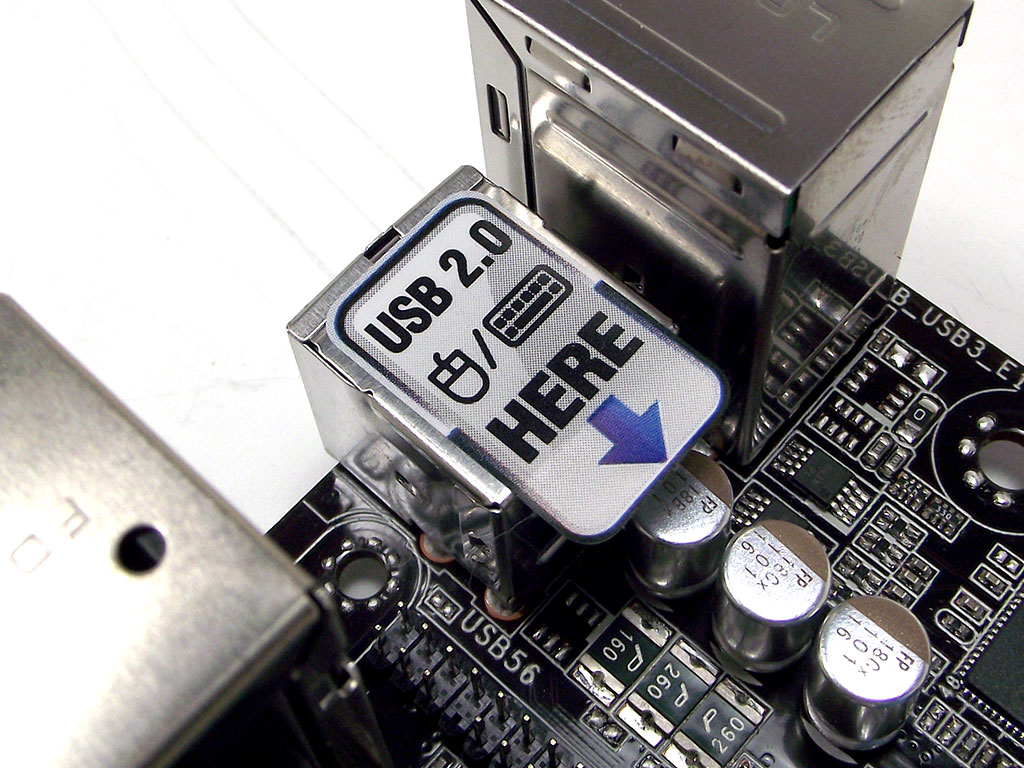
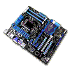
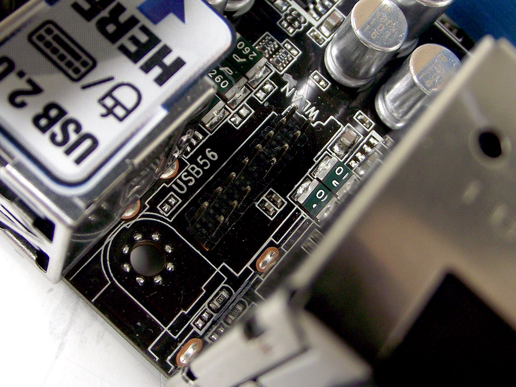
First and foremost, with the ASUS P8Z77-V there is something that needs to be mentioned, and that's shown in the first image above. There are just two USB 2.0 ports on the back, and in order to get things working right in BIOS when it comes to keyboard and mouse support, these ports need to be used for those devices. Once that is taken care of, however, mouse support in BIOS should be less of an issue than it has been on some products in the past. The BIOS chip itself sits by the lowest PCIe slot, fully socketed so that user replacement is easy.
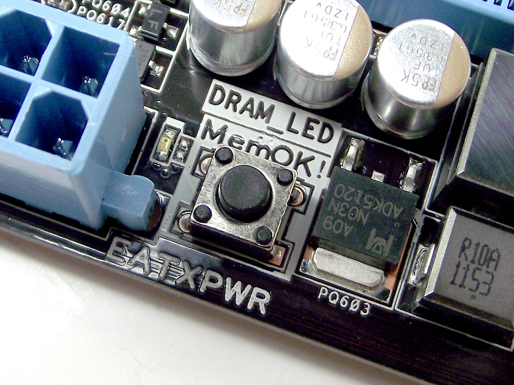
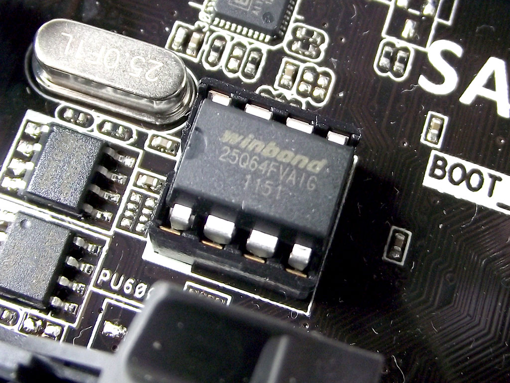
When you boot the board, there are a series of four LEDs placed around the board that serves as a guide for troubleshooting issues during the POST process. Should the boot fail, the light that remains lit will indicate in which area of the board the problem is, making fixes much easier. The DRAM LED, shown in the second image above, also serves to show "MemOK!" status. "MemOK!" is a built-in testing process that will test installed memory and set it to settings that guarantee a successful boot with any installed memory 99% of the time.
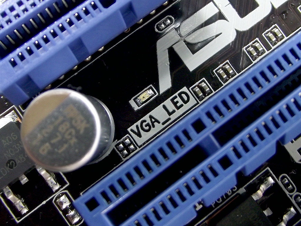
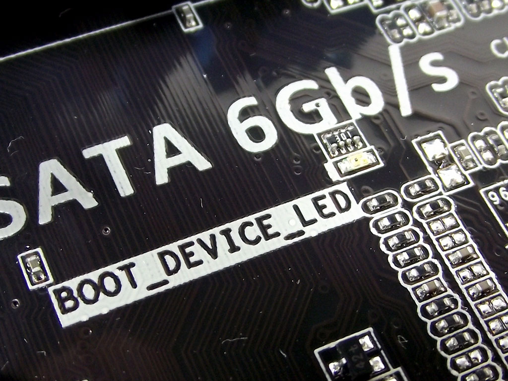
The VGA_LED is located just above the highest PCIe x16 slot, while the BOOT_DEVICE_LED is located just under the PCH heatsink. Once the POST process has completed, and your OS is loading, all four of the LEDs will have turned on and off again in the order shown in these pictures here.


There are a couple of other switches in various places, shown in these two images above. The first two, labeled "TPU" and "EPU', each pertain to clocking and power profiles. The "TPU" switch, an acronym shared between both ASUS and TechPowerUp, initiates an automatic overclock, while the "EPU" switch enables power saving technologies, mostly to do with how the CPU's VRM runs, and how the CPU's Turbo Boost and such clocking mechanisms work. The second image shows the BIOS Flashback button, used to flash the board's BIOS, even with no CPU or memory installed.
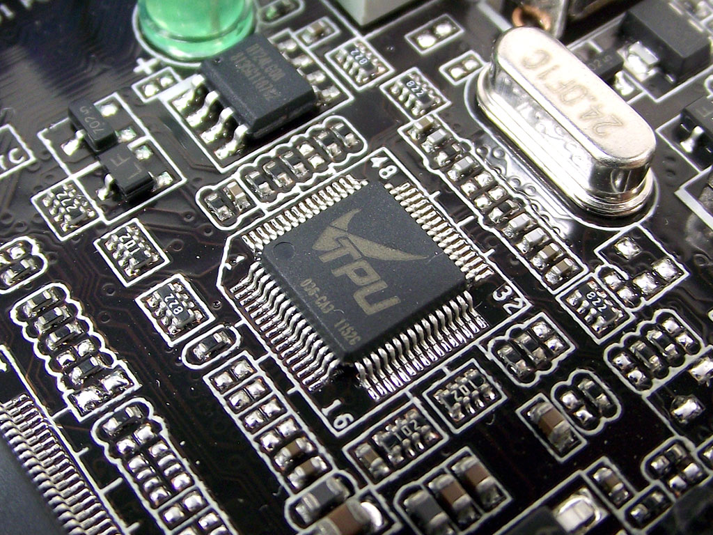
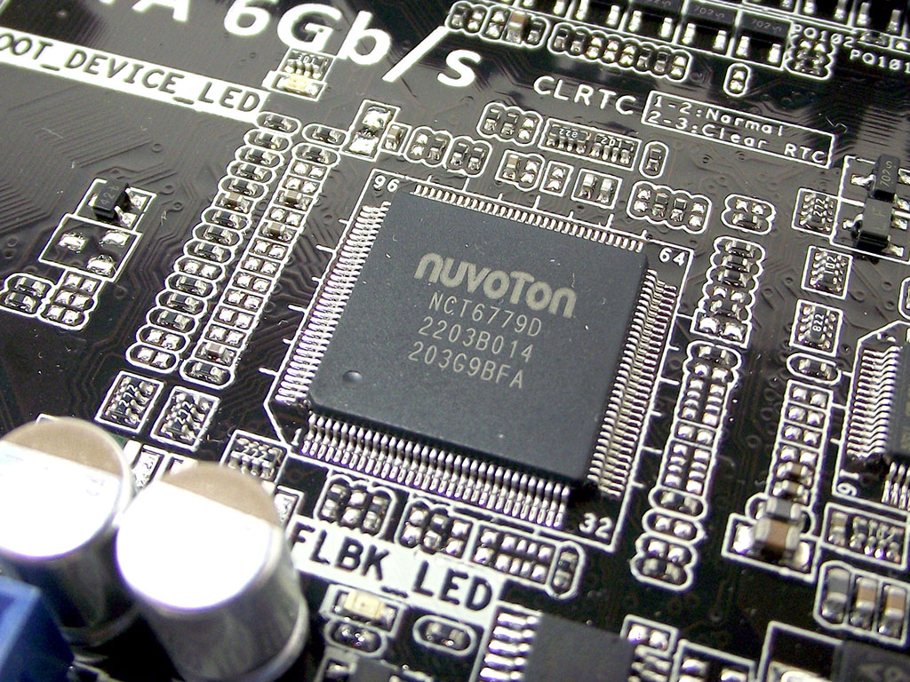
The "TPU" switch also mates with an onboard chip also labeled "TPU", or Turbo Processing Unit. In turn it works with the Nuvoton Super I/O chip, which is responsible for voltage monitoring and fan control.
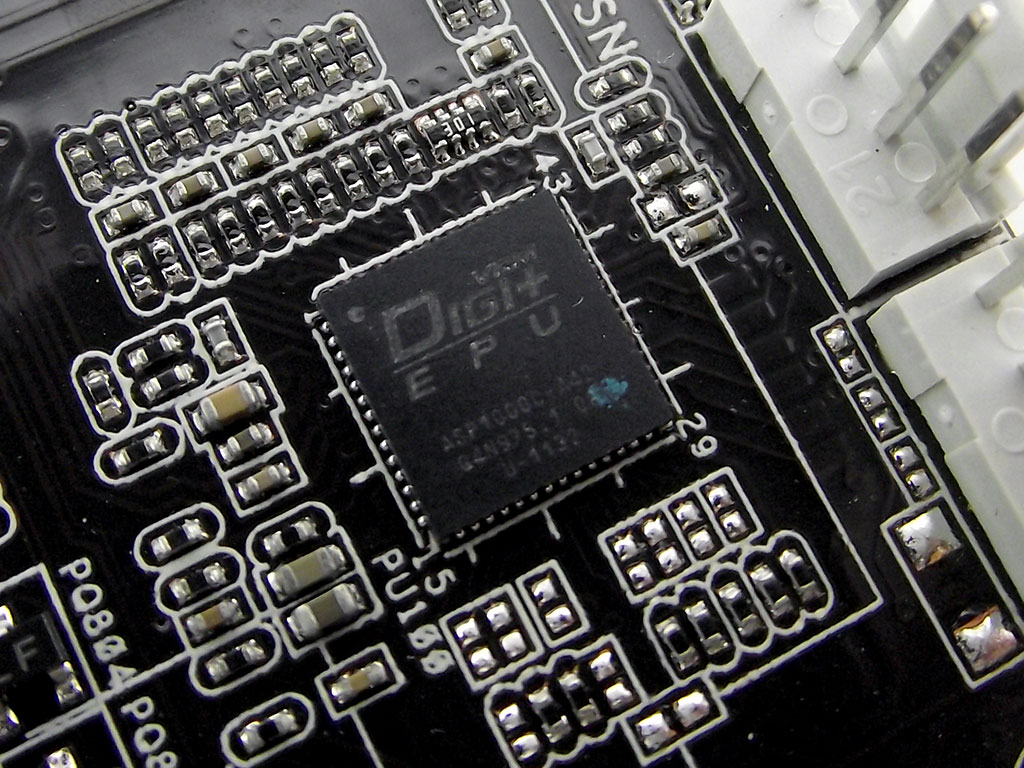
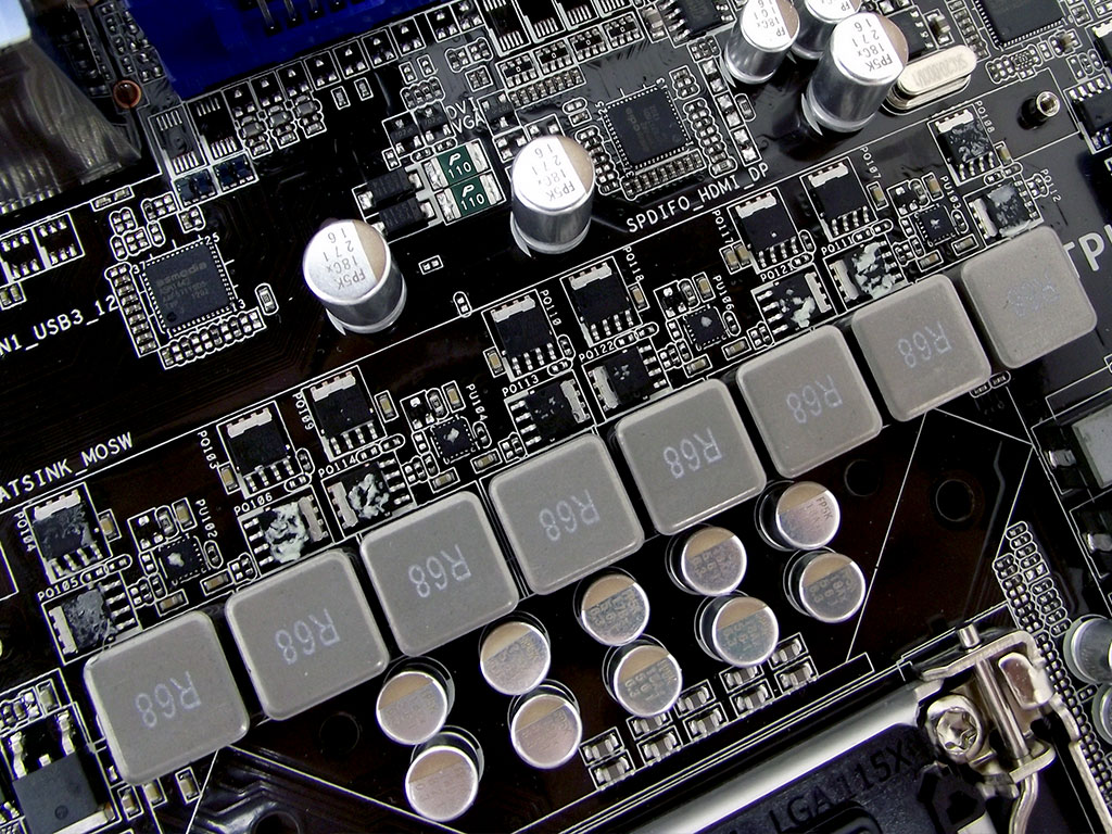
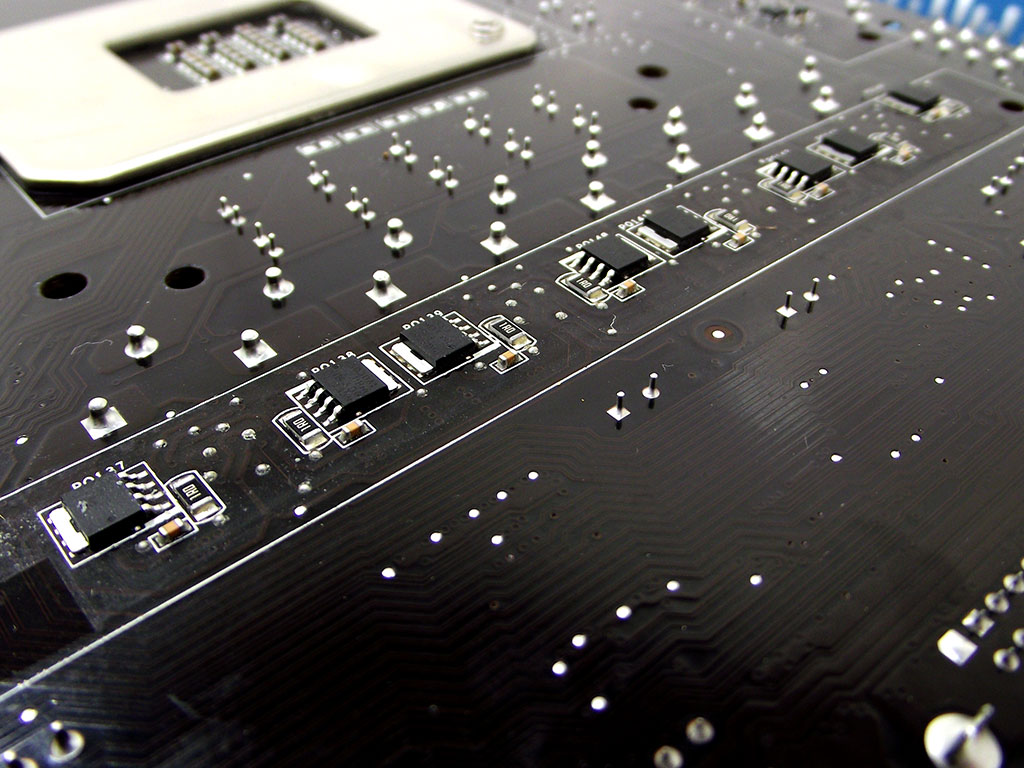
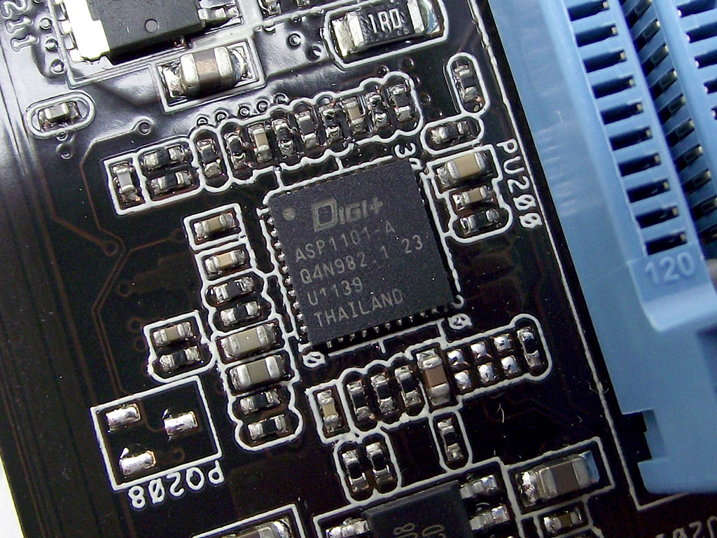
The board's VRM sections are fairly complex, too. Pictured above is the main DIGI+ controller, for the CPU VRM, which I found hidden under the upper MOSFET heatsink. The VRM itself for the CPU proper consists of eight matched phases, broken down into four pairs that are each connected to the controller via a dual-channel driver. The MOSFETs are arranged in triplets for each phases, with the third MOSFET for each phase located on the backside of the board shown in the third image above.
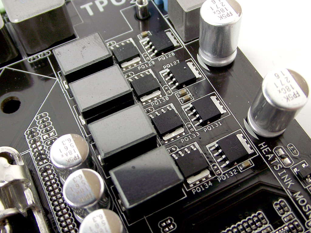
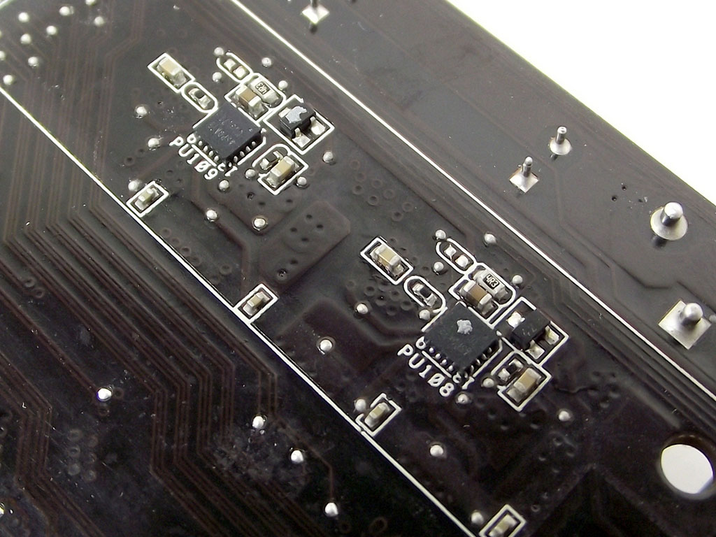
The iGPU VRM consists of four seperate phases, which are driven by the same controller. The input drivers are located on the backside of the board this time however.
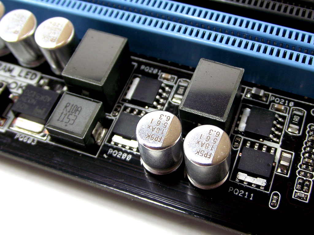
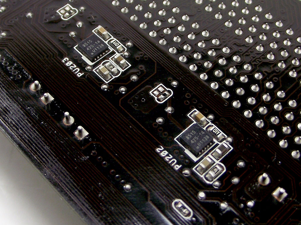
The DIMM VRM has its own controller, pushing two phases, very similar in design to the iGPU phases, even with input drivers located on the reverse side of the board.
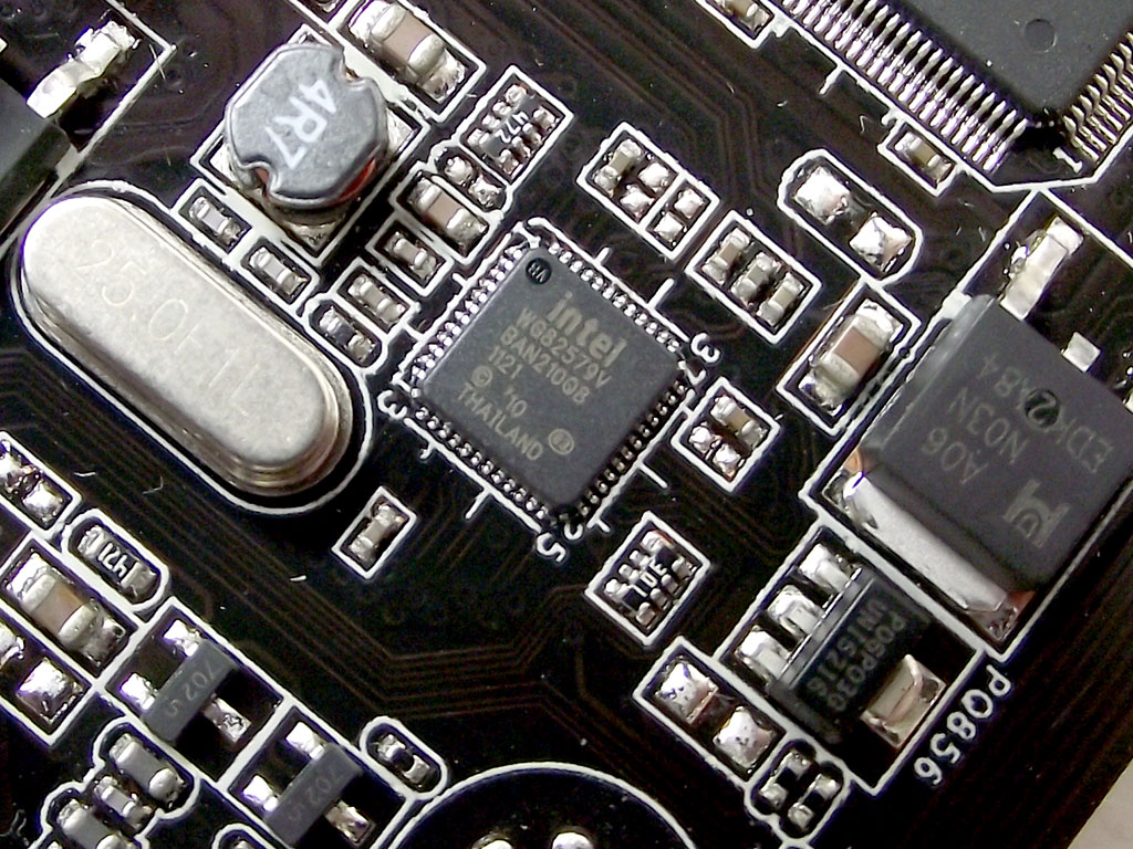
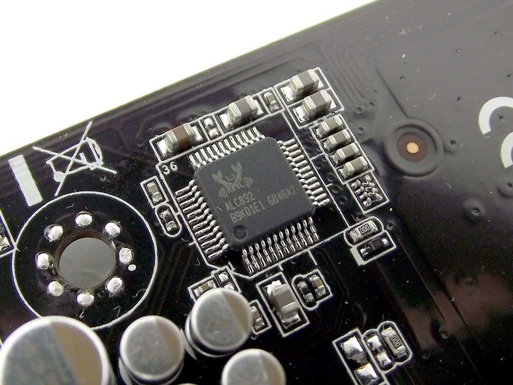
The LAN controller is an Intel WG82579V, one of the more favored controllers on the market right now. Audio is provided by a Realtek ALC892, not exactly the most high end of CODECs, but it's not that bad, either.
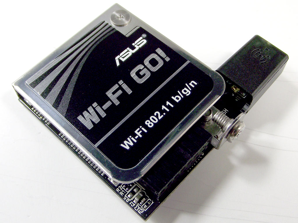
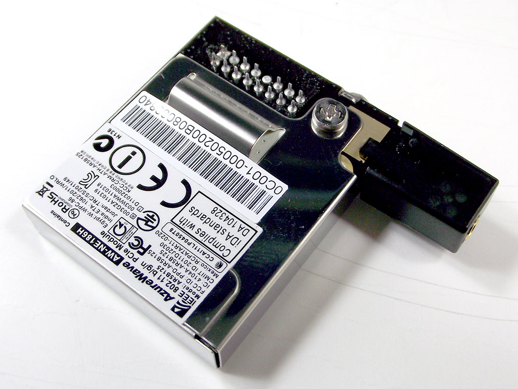
The add-on Wi-Fi GO! wireless card features 802.11 b/g/n connectivity, with a controller manufactured by AzureWave. It connects to the motherboard using USB, driven by the Intel Z77 Express chipset.
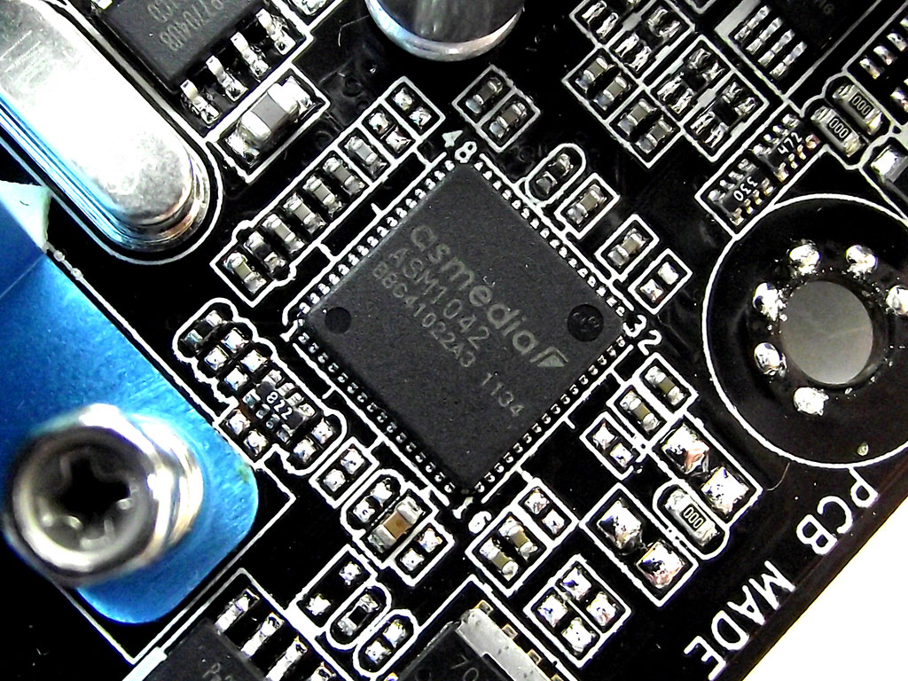
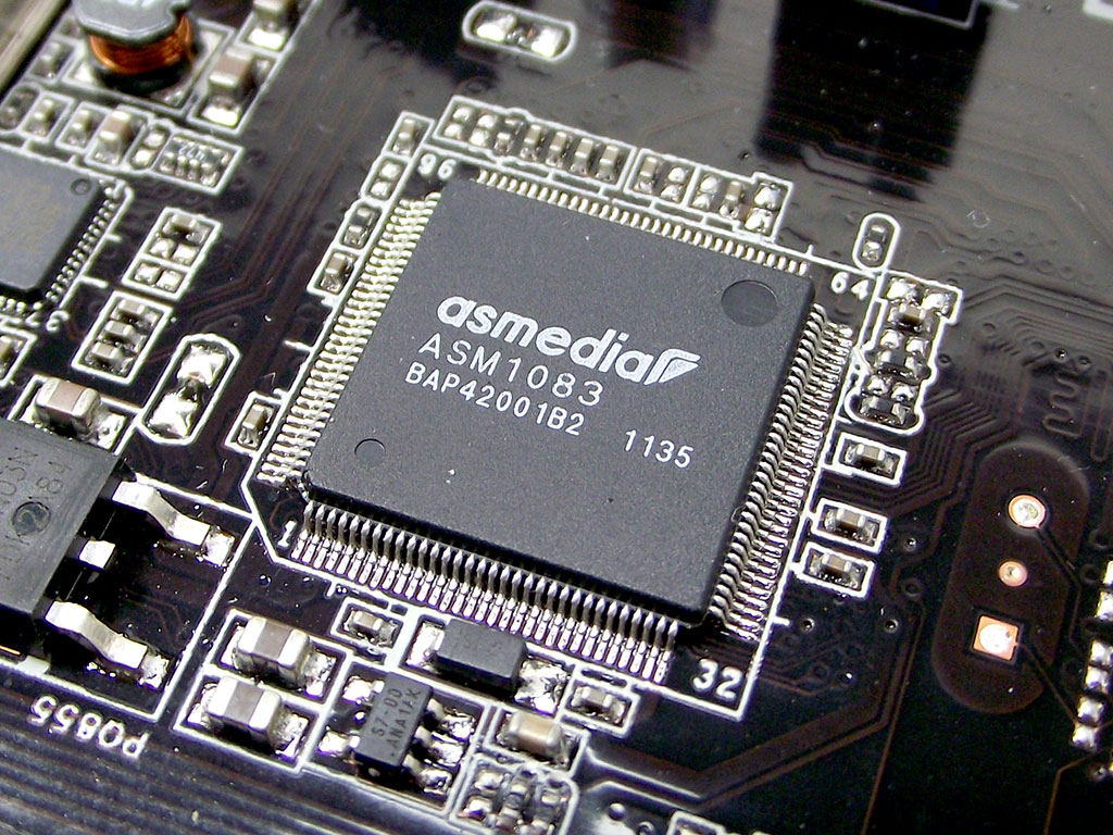
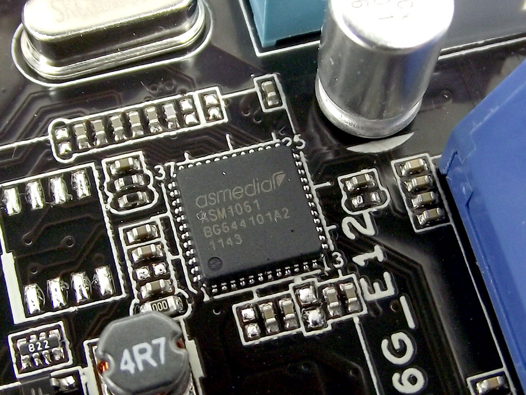
USB 3.0 ports on the Rear I/O are provided by an ASMedia ASM1083 PCIe to PCI converter, and the ASM1061 SATA 6 Gb/s controller.
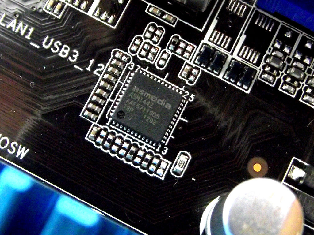
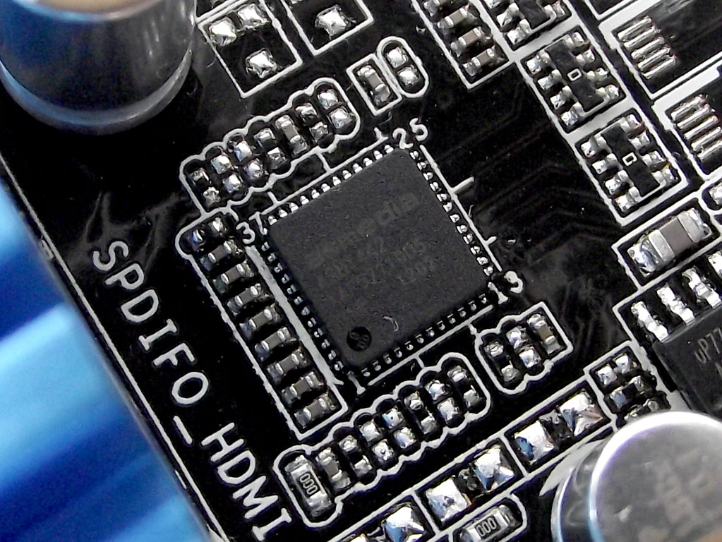
The TMDS switches are also provided by ASMedia, with dual ASM1442 parts shown above.
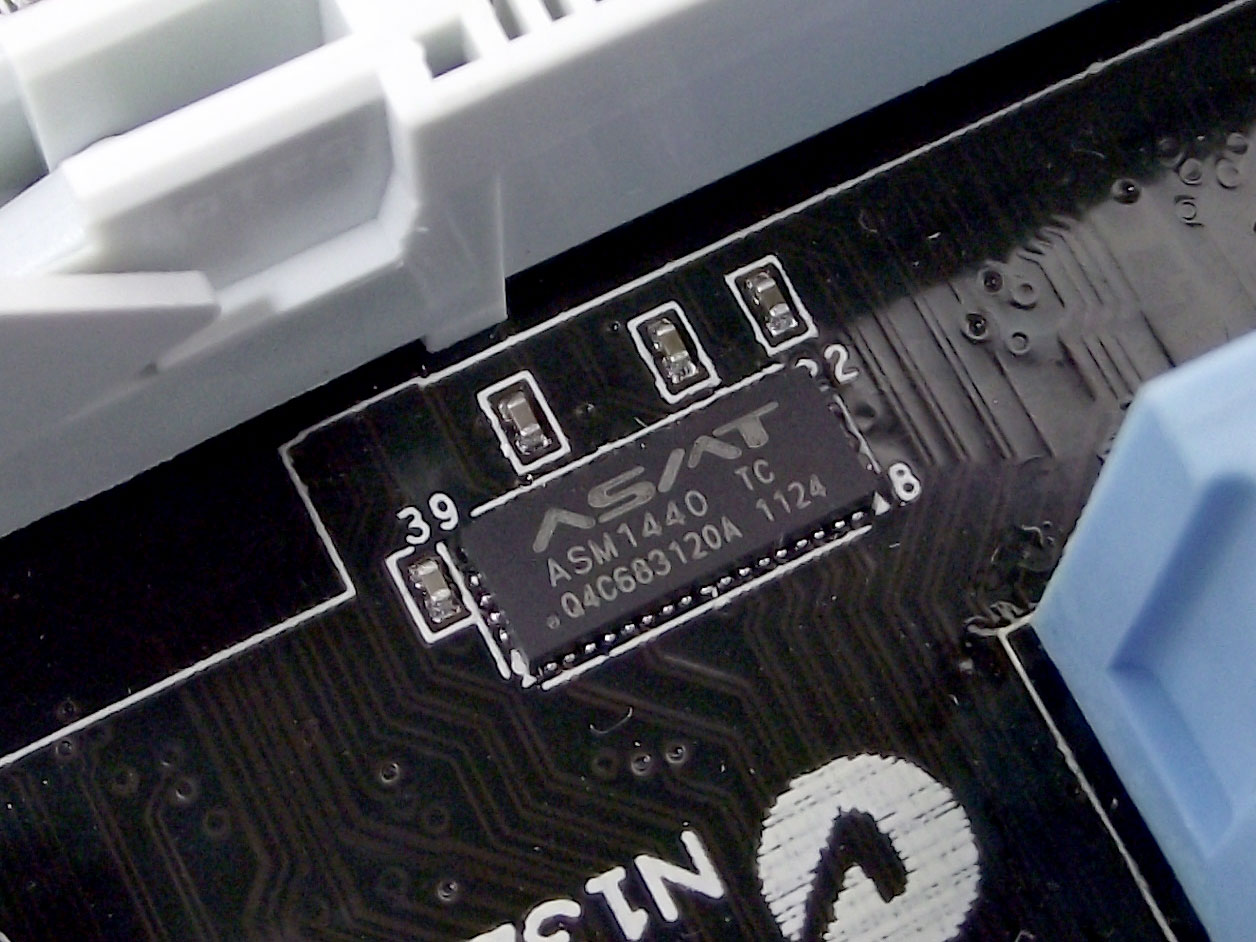
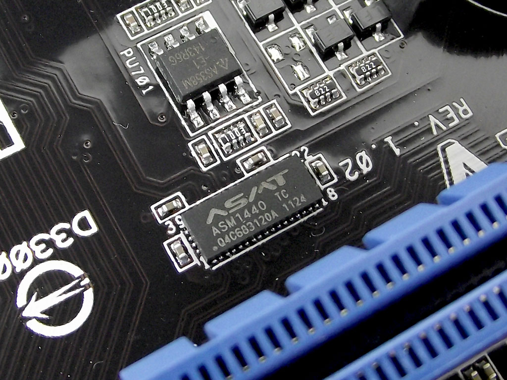
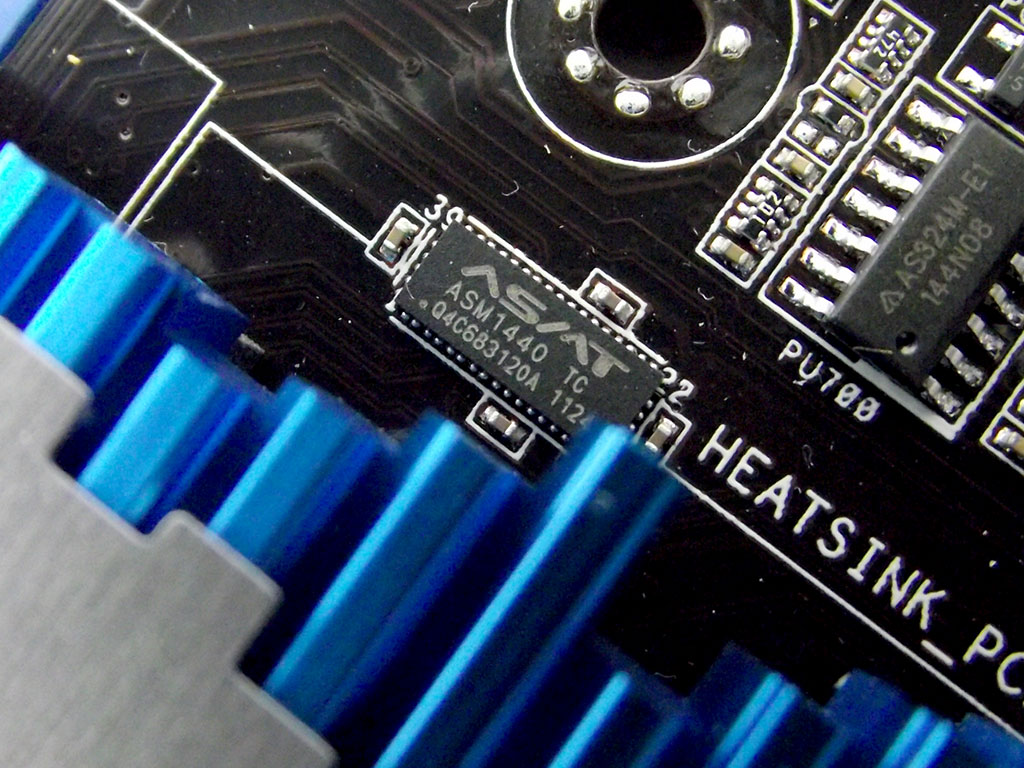
Both PCIe x1 slots and the ASMedia-driven SATA ports share their PCIe link to the Intel Z77 Express PCH with the third PCIe x16 slot (black), which has a default PCIe 2.0 x1 electrical link to the PCH, so that all slots and devices are active.
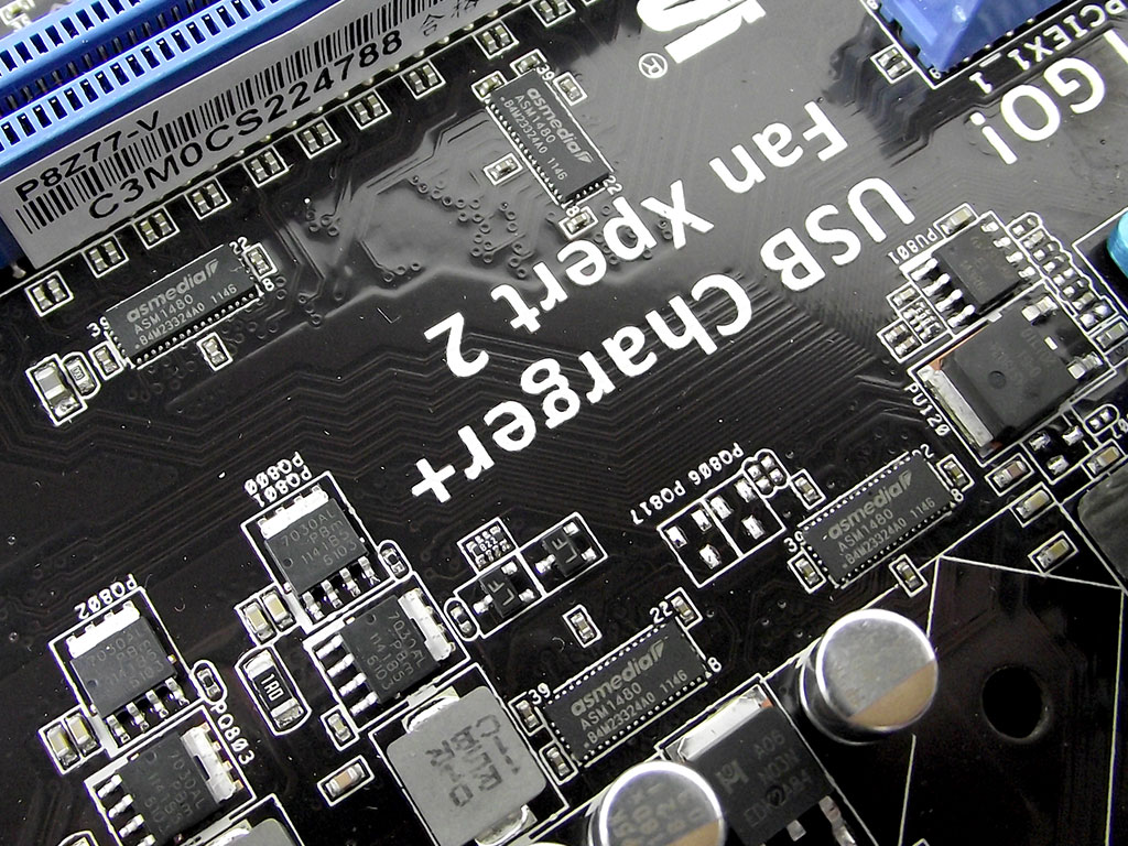
This lane switching is done by more ASMedia parts, none other than the ASM1440. The secondary PCIe slot (white) features a PCIe 3.0 x8 link direct to the CPU, connects via PCIe 3.0-complaint ASM1480 parts shown in the last image above. ASMedia sure provides alot of what makes this board work, with no less than twelve components and controllers manufactured by ASMedia!
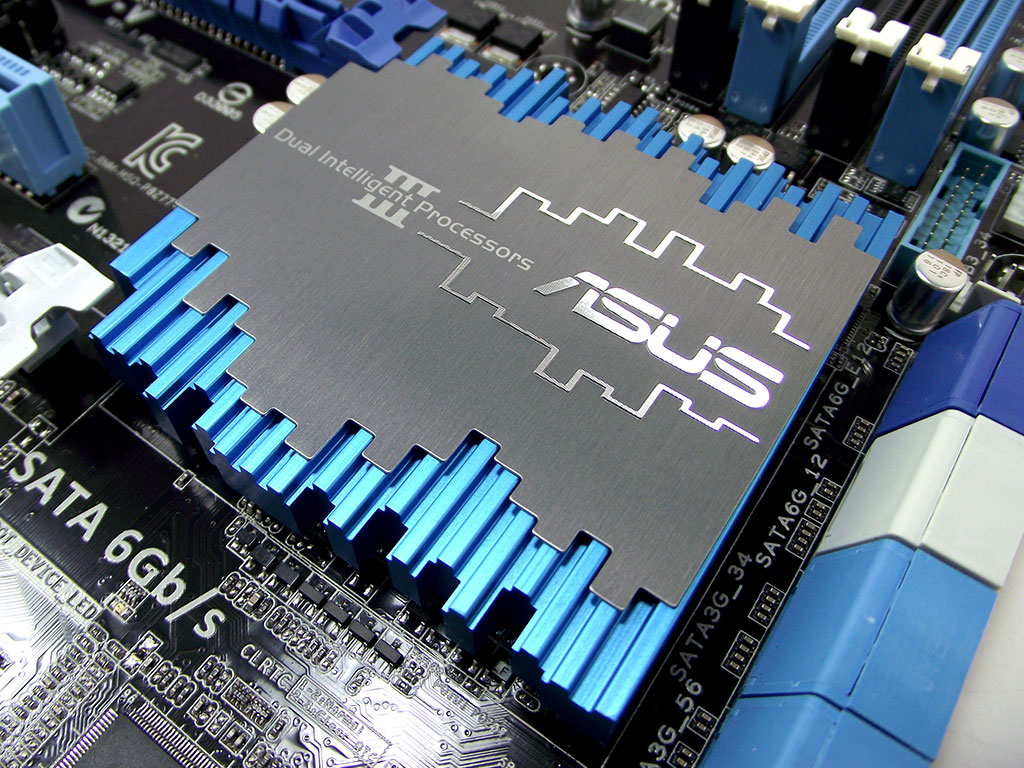
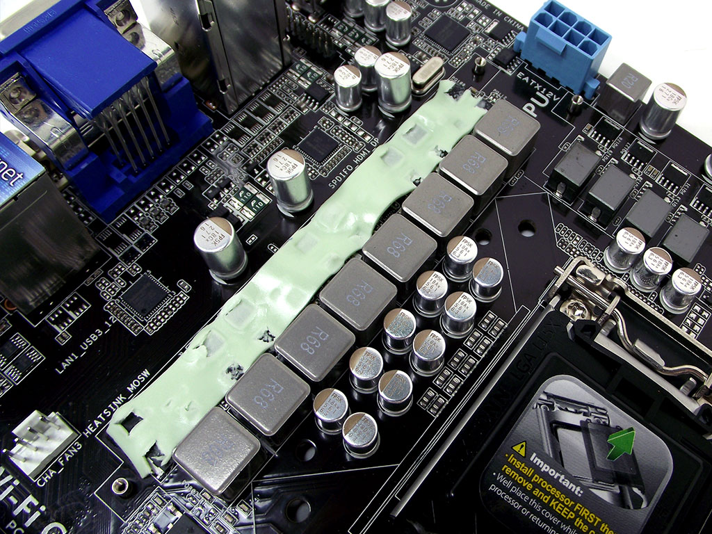
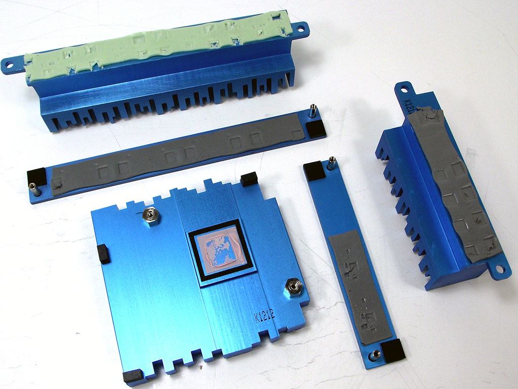
The cooling on the ASUS P8Z77-V is composed by large blue-anodized aluminium coolers, one for the chipset, and four for the VRM bits. The CPU main phases use a fairly soft and pliable thermal pad that is easily distorted by mounting the cooler, so unless you plan to watercool the board, I don't suggest you remove the cooler. Both the main CPU VRM cooler, as well as the iGPU phase cooler attach to the board using screws that press the board between the coolers on the top, and plates on the rear of the board that cover other VRM components, and each made perfect contact with all critical parts, including the CPU VRM controller itself.
Feb 23rd, 2025 16:34 EST
change timezone
Latest GPU Drivers
New Forum Posts
- Ssd for new built. (6)
- Warning about DOCP (14)
- Monitor Battle! Help me choose between two contenders (39)
- RTX 50 Series silently removed 32-bit PhysX support. (48)
- atx 12v vs eps 12v (1)
- 5800x (and other Zen 3 chips) PBO settings/Temperature fix (982)
- It's happening again, melting 12v high pwr connectors (893)
- Post your Monster Hunter Wilds benchmark scores (138)
- Share your AIDA 64 cache and memory benchmark here (3021)
- TPU's Nostalgic Hardware Club (19992)
Popular Reviews
- MSI GeForce RTX 5070 Ti Ventus 3X OC Review
- ASUS GeForce RTX 5070 Ti TUF OC Review
- Ducky One X Inductive Keyboard Review
- Galax GeForce RTX 5070 Ti 1-Click OC White Review
- darkFlash DY470 Review
- MSI GeForce RTX 5070 Ti Vanguard SOC Review
- Gigabyte GeForce RTX 5090 Gaming OC Review
- MSI GeForce RTX 5070 Ti Gaming Trio OC+ Review
- Palit GeForce RTX 5070 Ti GameRock OC Review
- Fantech Aria II Pro Review
Controversial News Posts
- NVIDIA GeForce RTX 5090 Spotted with Missing ROPs, NVIDIA Confirms the Issue, Multiple Vendors Affected, RTX 5070 Ti, Too (440)
- AMD Radeon 9070 XT Rumored to Outpace RTX 5070 Ti by Almost 15% (302)
- AMD Plans Aggressive Price Competition with Radeon RX 9000 Series (271)
- AMD Radeon RX 9070 and 9070 XT Listed On Amazon - One Buyer Snags a Unit (247)
- Edward Snowden Lashes Out at NVIDIA Over GeForce RTX 50 Pricing And Value (241)
- AMD Denies Radeon RX 9070 XT $899 USD Starting Price Point Rumors (239)
- NVIDIA Investigates GeForce RTX 50 Series "Blackwell" Black Screen and BSOD Issues (221)
- New Leak Reveals NVIDIA RTX 5080 Is Slower Than RTX 4090 (215)