 4
4
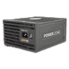
be quiet! Power Zone 850 W Review
Voltage Regulation, Hold-up Time & Inrush Current »A Look Inside & Component Analysis
Before reading this page, we strongly suggest a look at this article, which will help you understand the internal components of a PSU much better. Our main tool for the disassembly of the PSU is a Thermaltronics TMT-9000S soldering and rework station. It is of extreme quality and is equipped with a matching de-soldering gun. With such equipment in hand, breaking apart every PSU is like a walk in the park!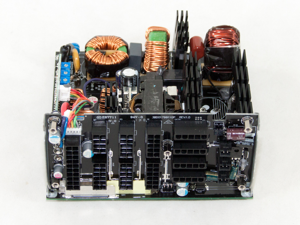
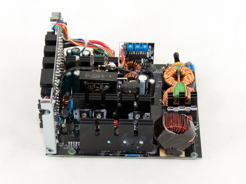
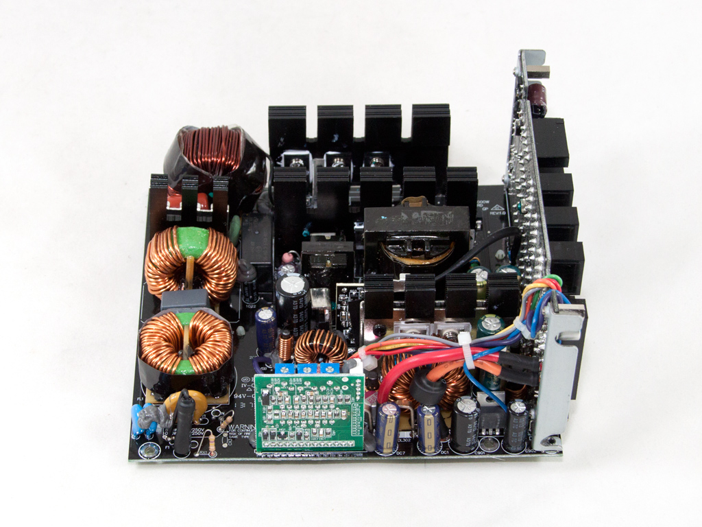
FSP builds all Power Zone units, and they use their favorite Active Clamp Reset Forward (ACRF) topology for this platforms because of its high efficiency and relatively low production cost.
The first part of the transient filter starts right at the AC receptacle and includes a single X and a pair of Y caps. It continues on the main PCB with two CM chokes, an X and two Y caps, and an MOV, which completes the transient filter.

An NTC thermistor provides protection against large inrush currents and an electromagnetic relay cuts the thermistor off the circuit once it finishes its job.
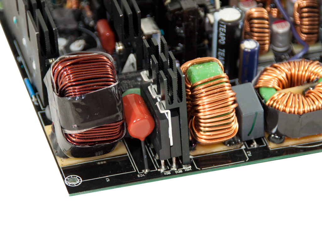
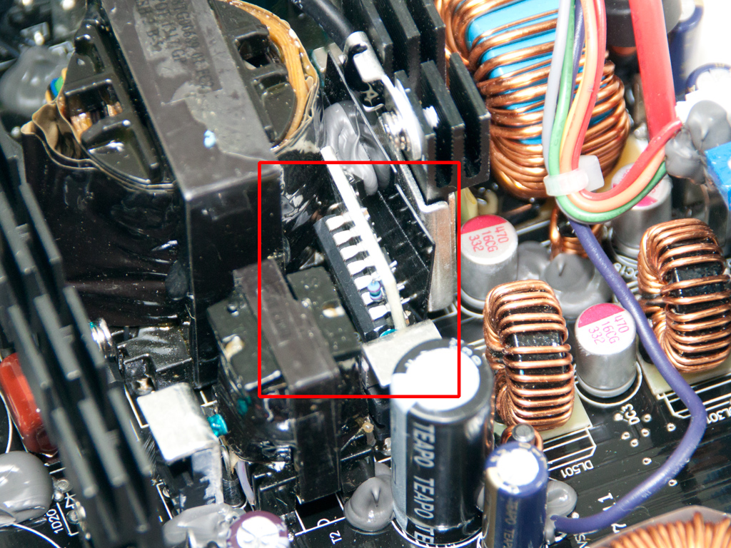
The two parallel bridge rectifiers are bolted to a dedicated heatsink. Their model number is D15XB-60, and each one can handle up to 15 A of current for a combined total of 30 A. Exactly the same rectifiers are used in the 1000 W unit.
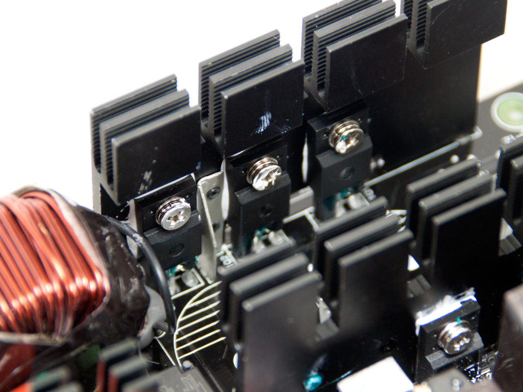
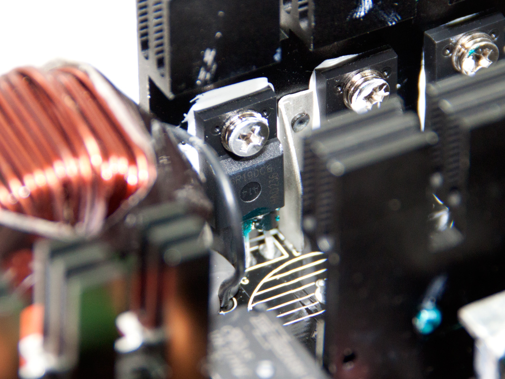
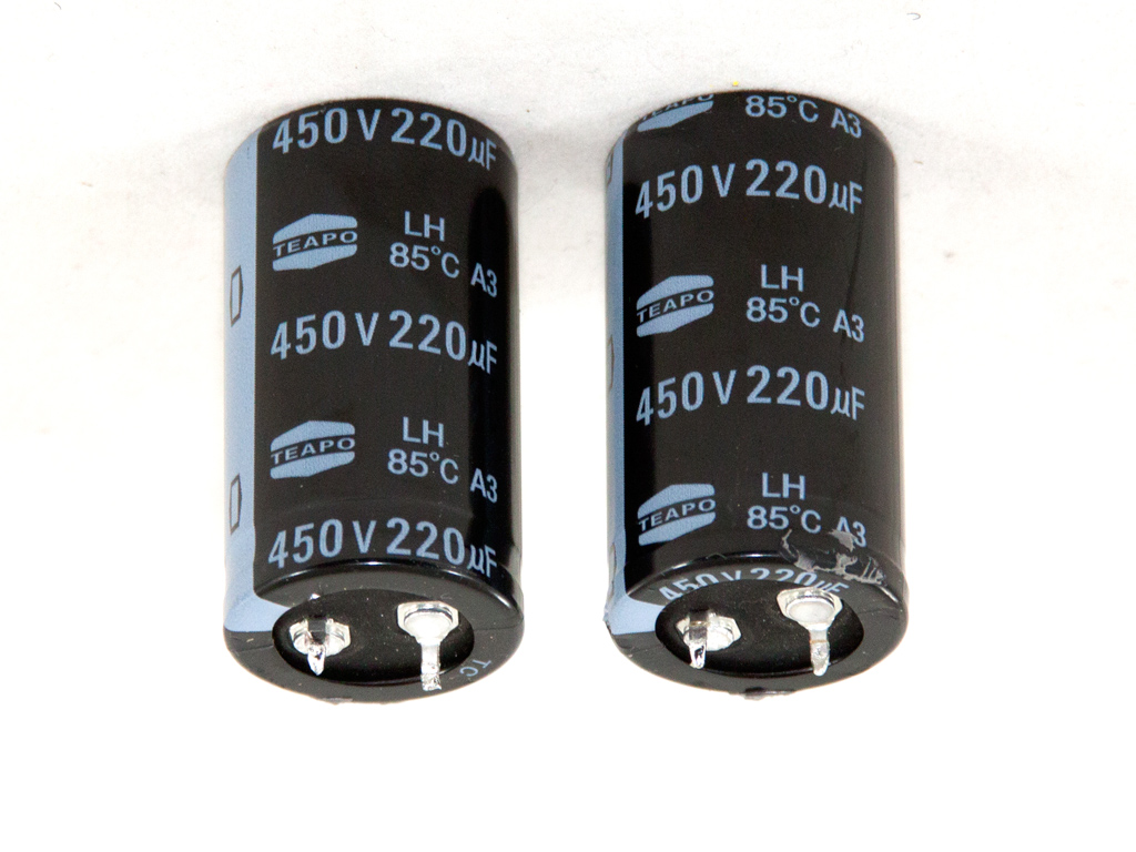
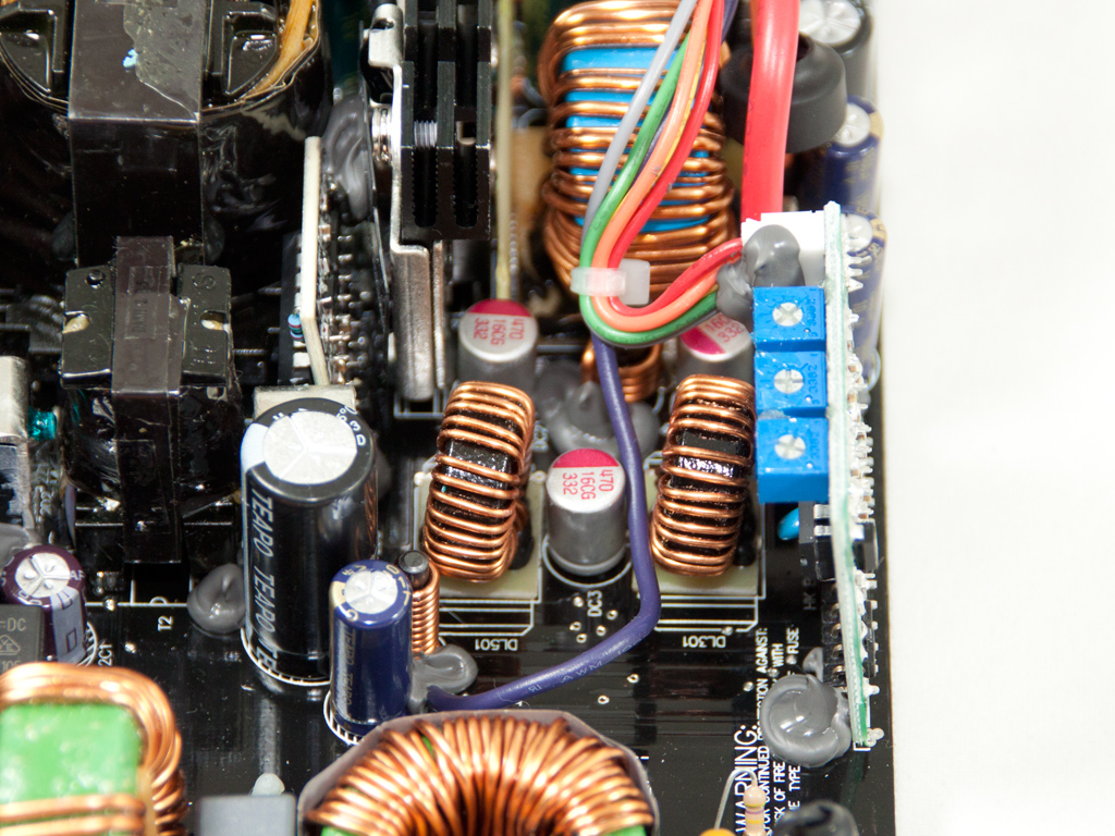
The APFC converter circuit uses three IPA60R190C6 fets and a single LXA08FP600 boost diode. The Power Zone 1000 W uses slightly stronger and more efficient fets, which means that they can handle more amperage, along with two boost diodes instead of one. The bulk caps are two Teapos with 440 µF combined capacity (450 V, 220 µF capacity, each, 105°C).

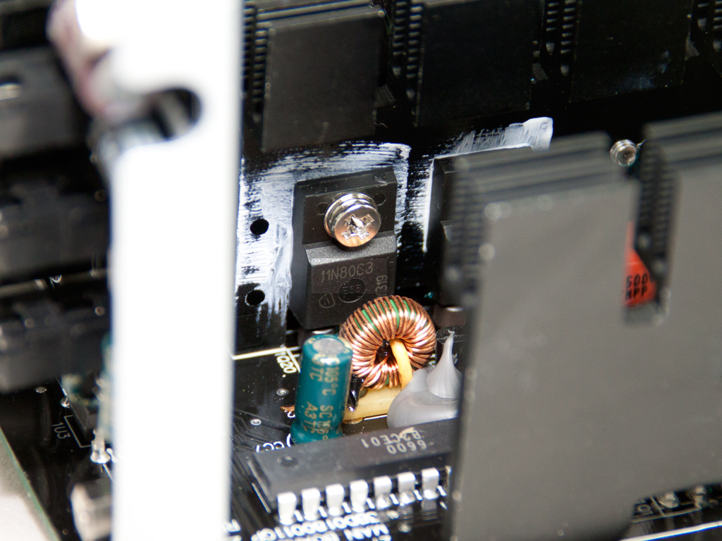
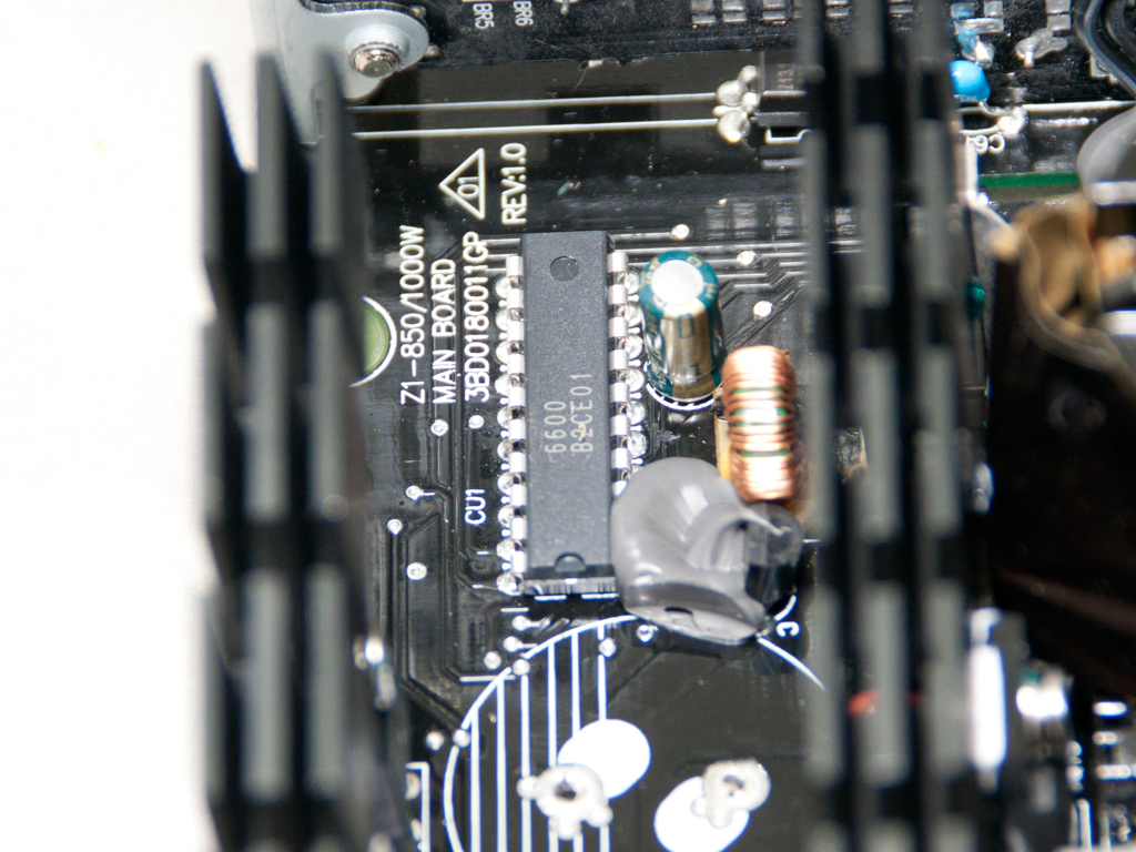
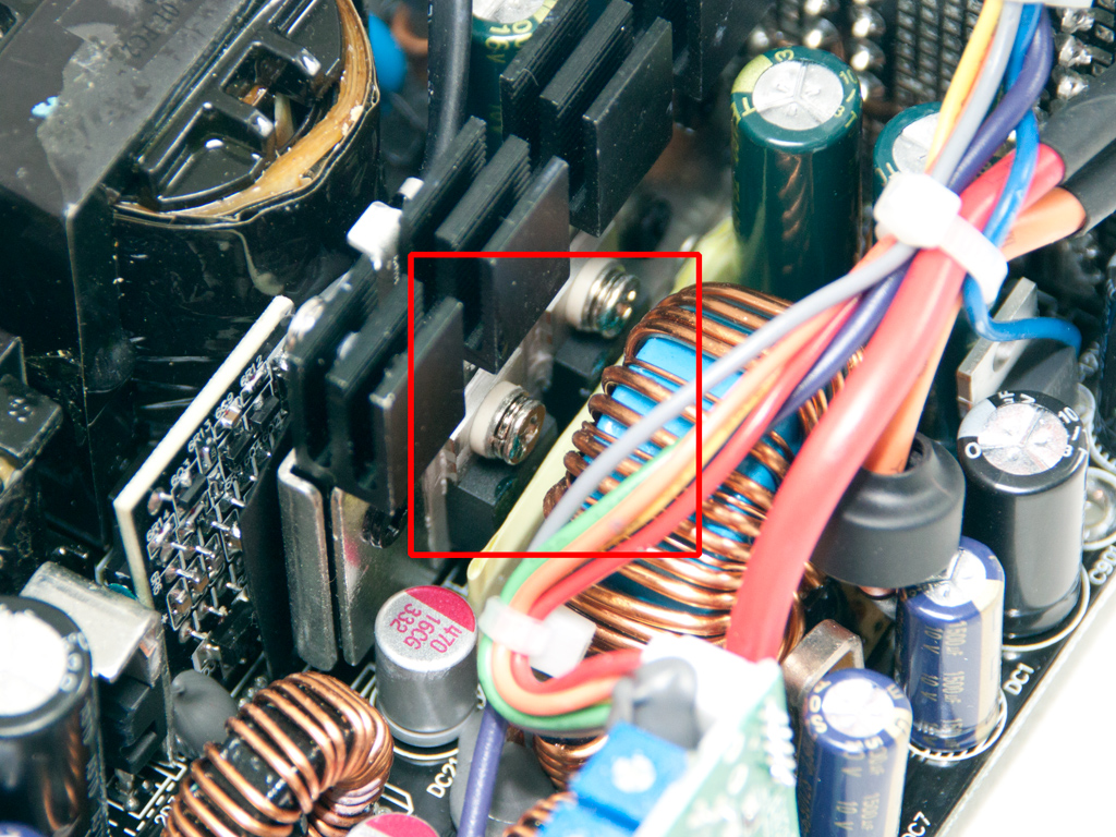
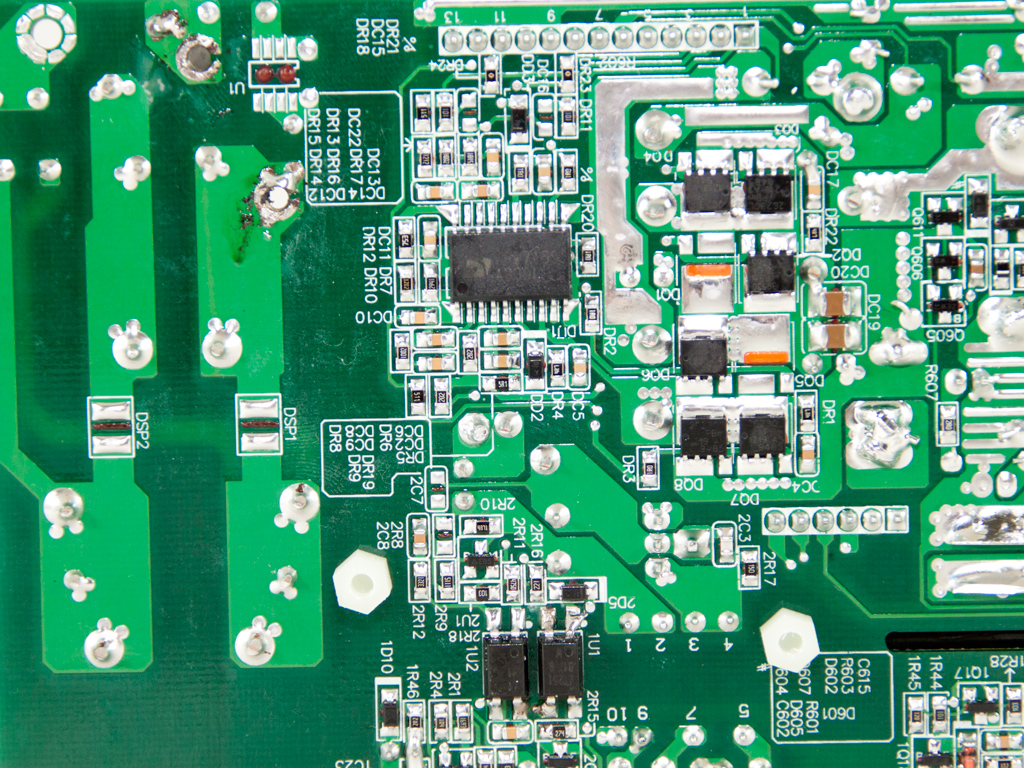
The Active Clamp Reset Forward topology this unit uses increases its efficiency to almost those of a Gold-certified unit - without the use of exotic components, like LLC resonant converters or fets with ultra-low RDS-on values. Three main switchers are used in the Power Zone 850 W. Two of these act as main switchers (Q1 and Q2) while the third is the reset switch (Q3), which disconnects the bulk capacitors while Q1 and Q2 are active. Also, while Q3 is open, power is transferred from the primary to the secondary side. The main advantage of ACRF is the almost lossless switching of Q1 and Q2, as voltage drained is very low while both are turned off. Two SPA11N80C3s in the Power Zone 850 W act as respective Q1 and Q2 switches, while an FQPF3N80C is the Q3 reset switch. Finally, an FSP 6600 IC for which there is no documentation available on the net acts as the APFC/PWM controller.
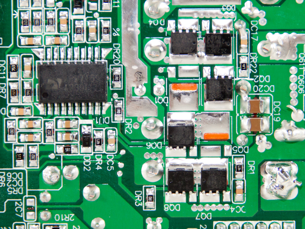
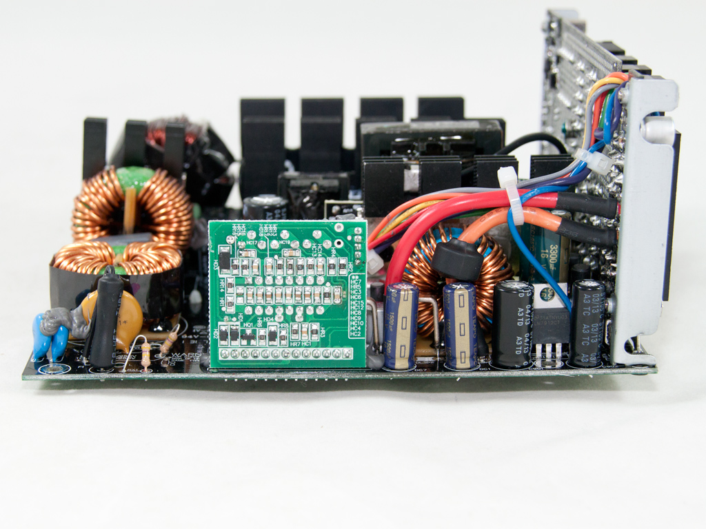
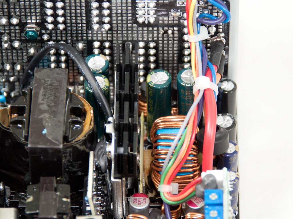
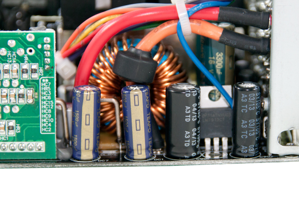
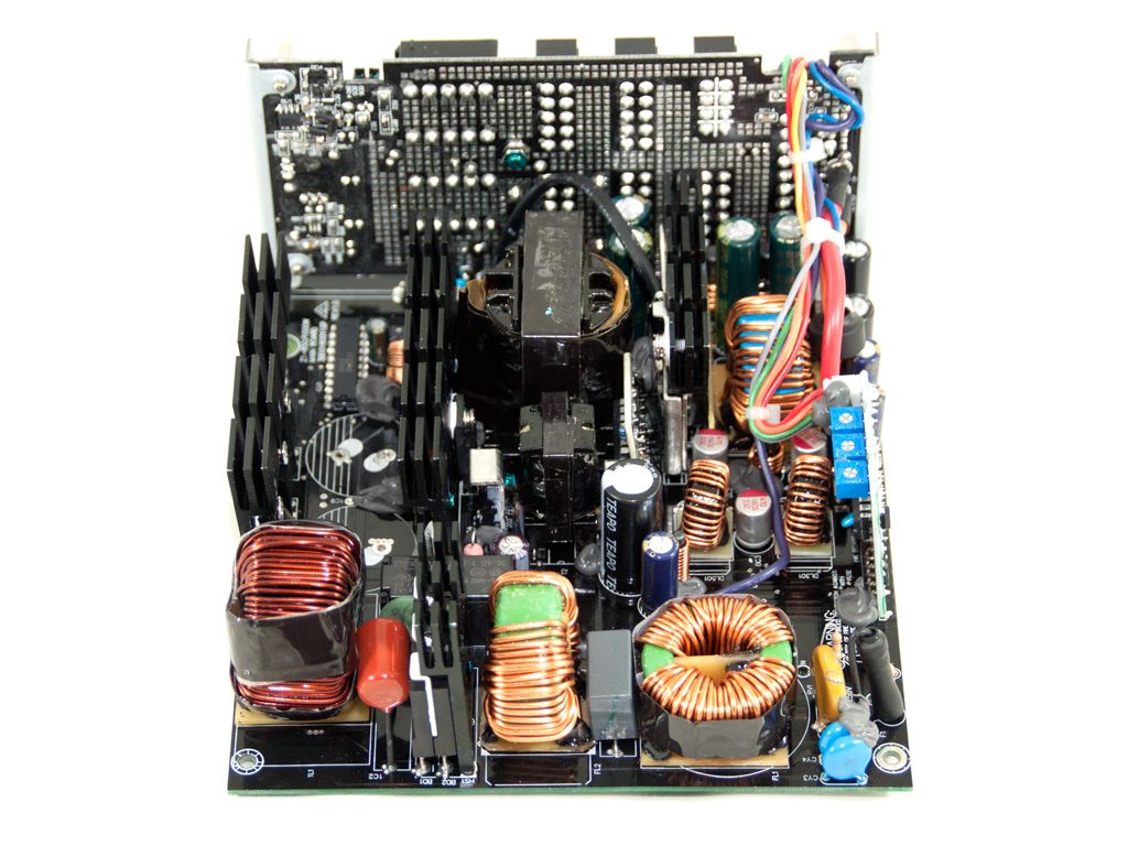
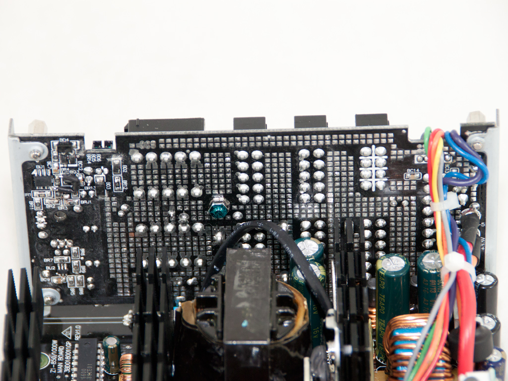
A synchronous design is used in the secondary side, where the generation of +12V is handled by two Infineon IPP023NE7N3 mosfets. The 1000 W model uses four fets of the same type here, so the difference is bigger than we expected. The minor rails are generated off +12V with the help of two DC-DC converters. The mosfets responsible for the regulation of the minor rails reside on the solder side of the main PCB and consist of a pair PBm1238C4s and two pair of PBm1219A5 fets. The common PWM controller for both DC-DC converters is an APW7159 IC, and we also found a proprietary FSP 6601 IC on a vertical daughterboard on the component side of the main PCB. Finally, all filtering caps of the secondary side, electrolytic and polymer, are provided by Teapo, with all electrolytics rated at 105°C.
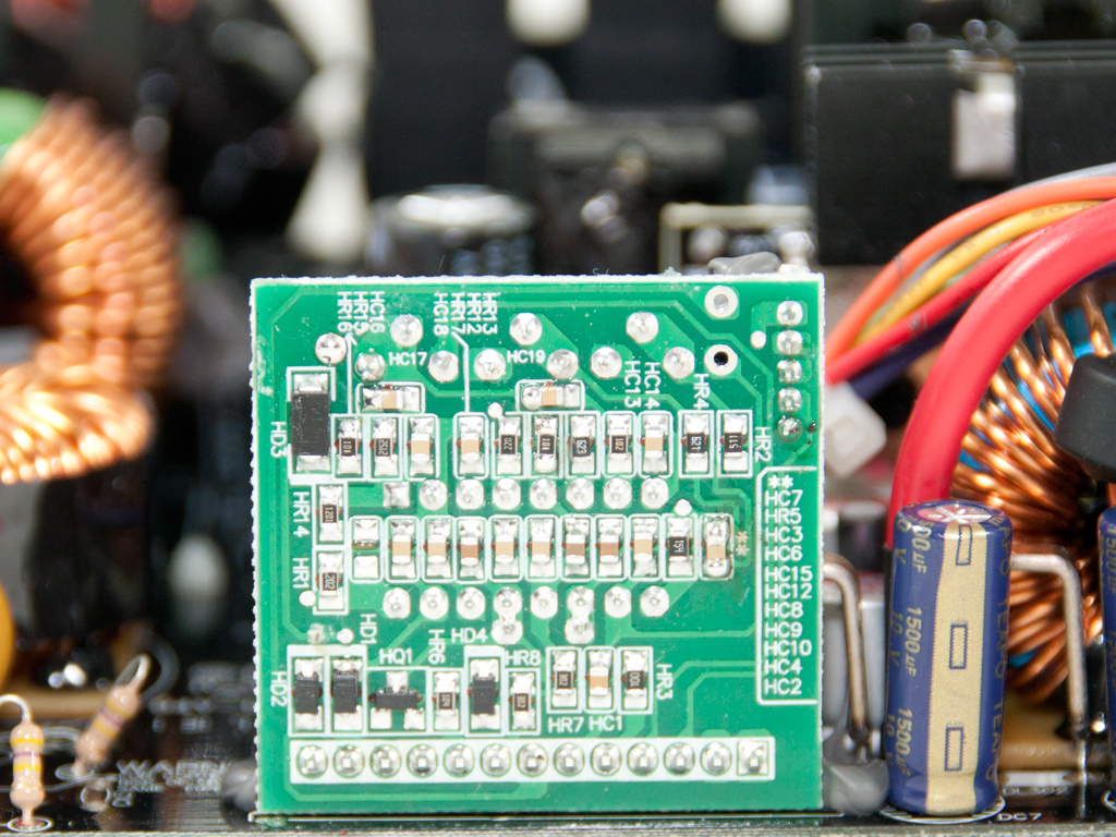
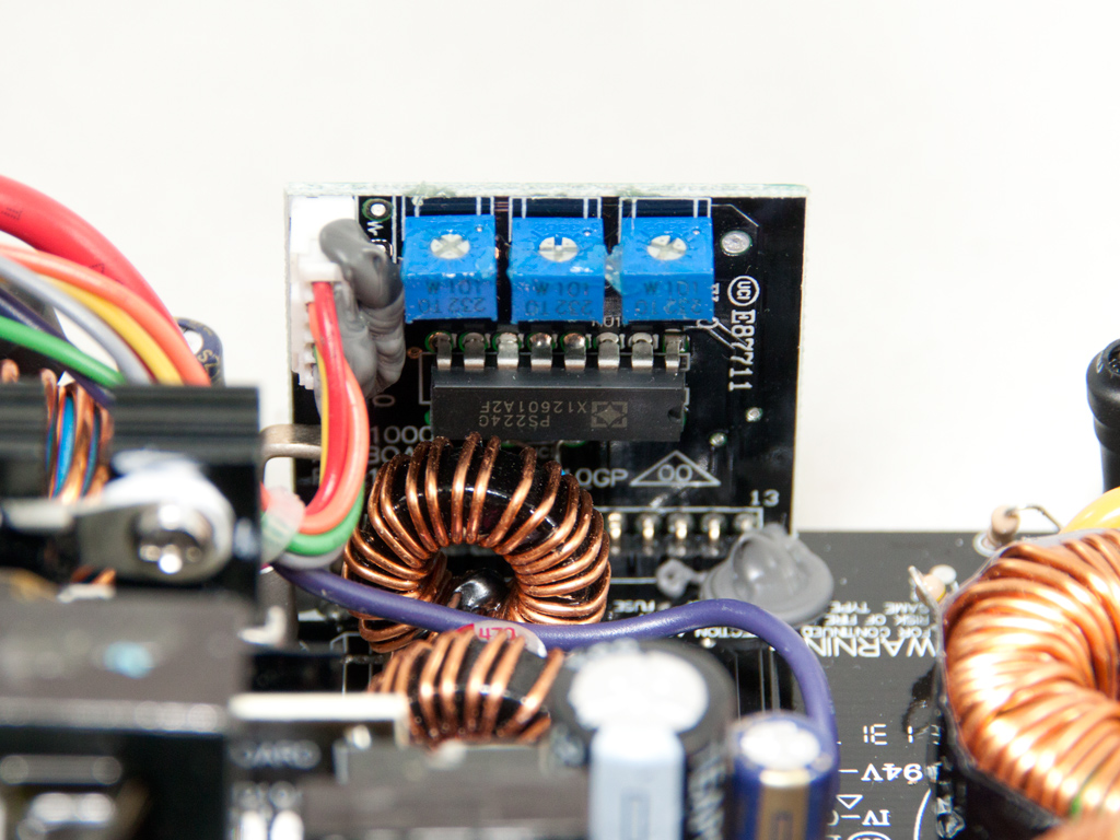
A vertical PCB located on the secondary side hosts the supervisor IC, a SITI PS224 that supports all protections except for OTP out of the box. The same IC provides OCP for up to two +12V rails, but this unit only has one. There are three potentiometers on top of this daughterboard. These probably allow you to adjust the thresholds of all available protections.
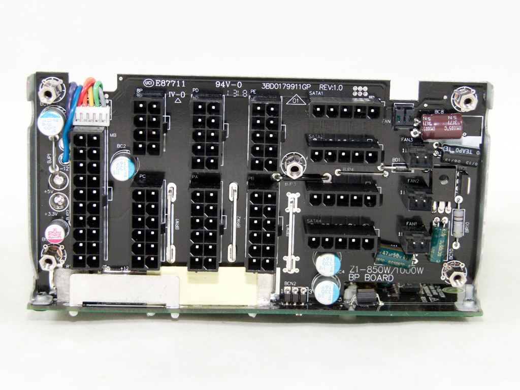

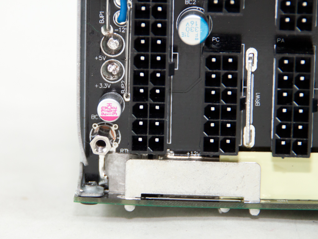
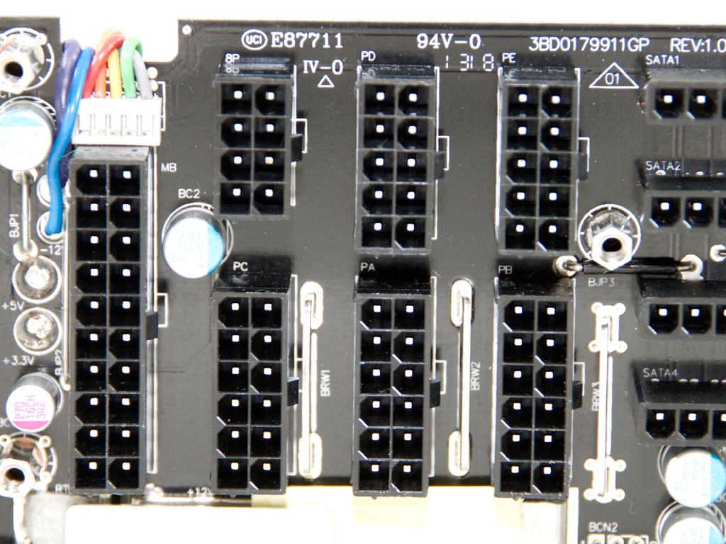
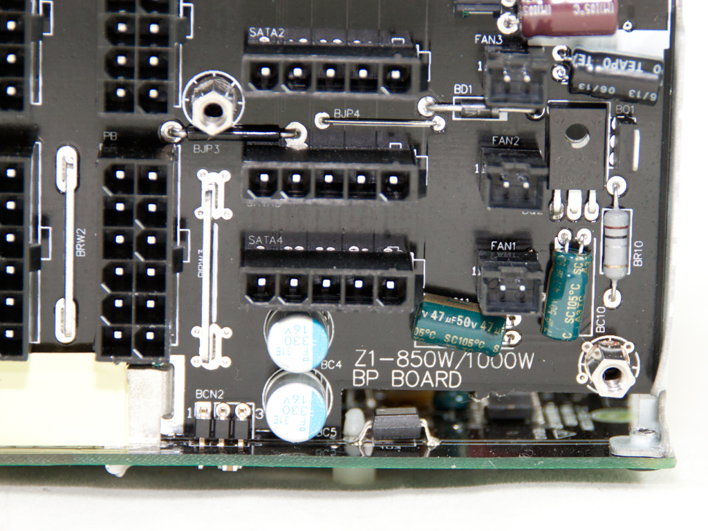
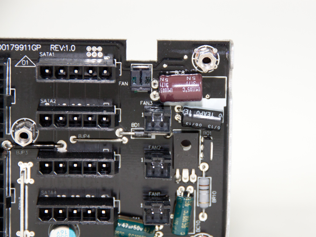
Soldering quality on the modular PCB is good, and we found a weird mix of Teapo and Nippon Chemi-Con polymer and electrolytic caps there. We also found an D882 NPN silicon transistor; it is used by the PSU's fan controller circuit. The aforementioned circuit can control up to three case fans.
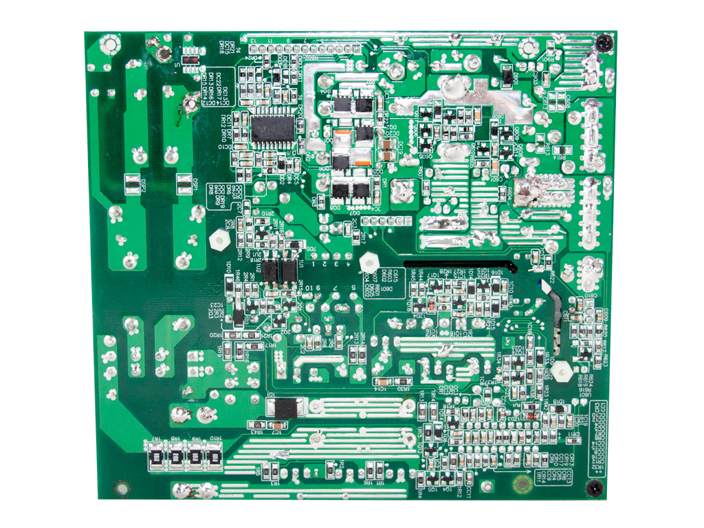
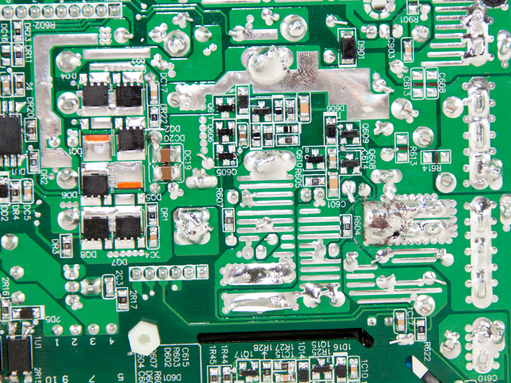
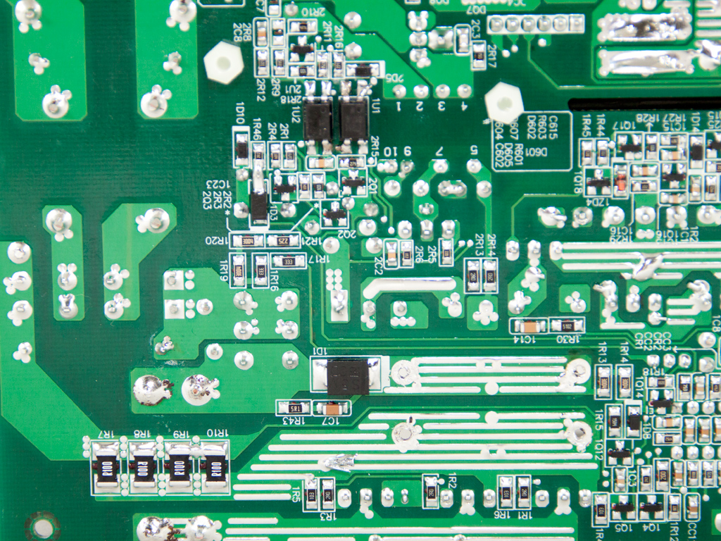
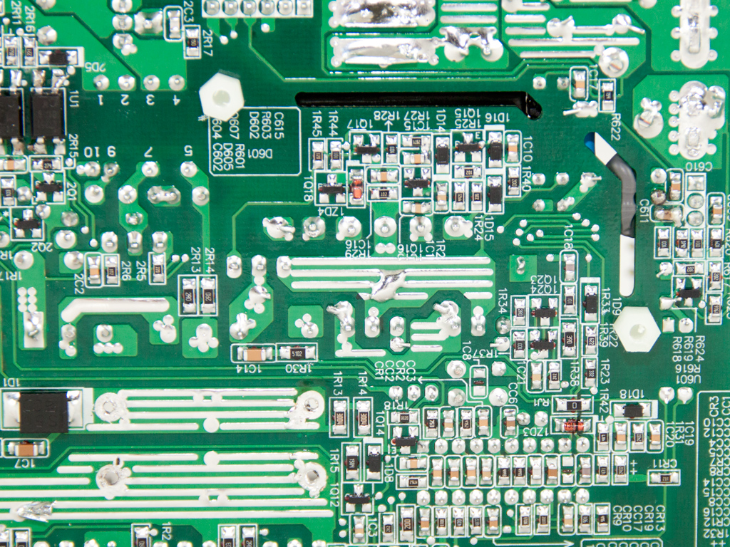
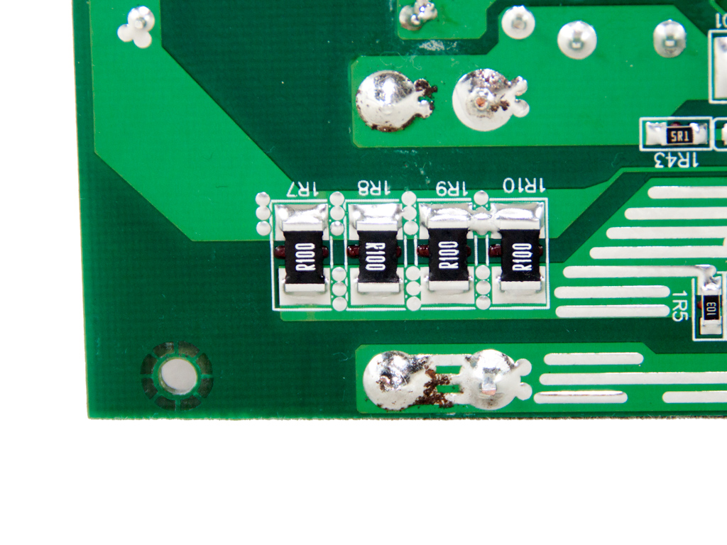
General soldering quality is good, but we spotted several joints where excess amounts of solder was used. While this won't influence the reliability or performance of the unit, it looks bad to the eye. We also noticed four current sense resistors which are usually located under the rail islands right below the PFC choke. These resistors most likely provide amperage feedback to the OCP circuit.

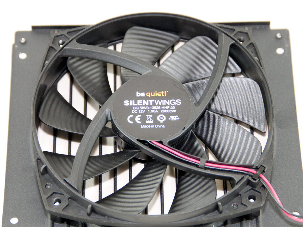
The high quality cooling fan is provided by be quiet! and belongs to the SilentWings series. Its model number is BQ SIW3-13525-HHF-29 (12 V, 1 A, 2900 RPM max), and we strongly believe it to be too powerful and noisy for the needs of this PSU. The fan controller circuit fortunately restricts its maximum rotational speed to 2550 RPM, which has it rotate the fan at low enough speeds for a quiet, but not whisper quiet operation most of the time.
Mar 4th, 2025 05:37 EST
change timezone
Latest GPU Drivers
New Forum Posts
- The future of RDNA on Desktop. (61)
- High-end build in the 2025 mad world situation (15)
- 1080ti with 0 vram (1)
- Game performance testing: are all SKUs necessary? (2)
- Windows 11 General Discussion (5772)
- Ryzen Owners Zen Garden (7706)
- It's happening again, melting 12v high pwr connectors (997)
- AWARD-Phoenix Legacy-HOW TO ADD BIOS NVMe M.2 SSD SUPPORT TO OLD MOTHERBOARDS? (0)
- Maxsun RX580 graphics card crashes (3)
- Matrix Deliverance - a fan-made video based on Kingdom Come: Deliverance II game (0)
Popular Reviews
- AMD Radeon RX 9070 Series Technical Deep Dive
- ASUS GeForce RTX 5070 Ti TUF OC Review
- EIZO FlexScan EV4340X Review - A Multitasking Powerhouse
- AMD Ryzen 7 9800X3D Review - The Best Gaming Processor
- be quiet! Pure Base 501 DX Review
- RAWM ES21M Review
- MSI GeForce RTX 5070 Ti Vanguard SOC Review
- MSI GeForce RTX 5070 Ti Ventus 3X OC Review
- ASUS ROG Harpe Ace Mini Review
- MSI GeForce RTX 5070 Ti Gaming Trio OC+ Review
Controversial News Posts
- NVIDIA GeForce RTX 50 Cards Spotted with Missing ROPs, NVIDIA Confirms the Issue, Multiple Vendors Affected (513)
- AMD Plans Aggressive Price Competition with Radeon RX 9000 Series (278)
- AMD Radeon RX 9070 and 9070 XT Listed On Amazon - One Buyer Snags a Unit (260)
- AMD Mentions Sub-$700 Pricing for Radeon RX 9070 GPU Series, Looks Like NV Minus $50 Again (248)
- NVIDIA Investigates GeForce RTX 50 Series "Blackwell" Black Screen and BSOD Issues (244)
- AMD RDNA 4 and Radeon RX 9070 Series Unveiled: $549 & $599 (230)
- AMD Radeon RX 9070 and 9070 XT Official Performance Metrics Leaked, +42% 4K Performance Over Radeon RX 7900 GRE (195)
- AMD Radeon RX 9070-series Pricing Leaks Courtesy of MicroCenter (158)