 5
5
be quiet! Straight Power 10 CM 800 W Review
Ripple Measurements »Advanced Transient Response Tests
In these tests, we monitor the response of the PSU in two different scenarios. First, a transient load (10 A at +12V, 5 A at 5V, 5 A at 3.3V, and 0.5 A at 5VSB) is applied to the PSU for 200 ms while the latter is working at 20% load. In the second scenario, the PSU, while working at 50% load, is hit by the same transient load. In both tests, we measure the voltage drops the transient load causes using our oscilloscope. The voltages should remain within the regulation limits defined by the ATX specification. We must stress here that these tests are crucial since they simulate transient loads a PSU is very likely to handle (e.g., booting a RAID array, an instant 100% load of CPU/VGAs, etc.). We call these tests "Advanced Transient Response Tests", and they are designed to be very tough to master, especially for a PSU with a capacity below 500 W.| Advanced Transient Response 20% | ||||
|---|---|---|---|---|
| Voltage | Before | After | Change | Pass/Fail |
| 12 V | 12.174V | 12.013V | 1.32% | Pass |
| 5 V | 5.056V | 4.954V | 2.02% | Pass |
| 3.3 V | 3.343V | 3.194V | 4.46% | Pass |
| 5VSB | 5.035V | 4.991V | 0.87% | Pass |
| Advanced Transient Response 50% | ||||
|---|---|---|---|---|
| Voltage | Before | After | Change | Pass/Fail |
| 12 V | 12.122V | 11.937V | 1.53% | Pass |
| 5 V | 5.035V | 4.938V | 1.93% | Pass |
| 3.3 V | 3.318V | 3.171V | 4.43% | Pass |
| 5VSB | 5.005V | 4.943V | 1.24% | Pass |
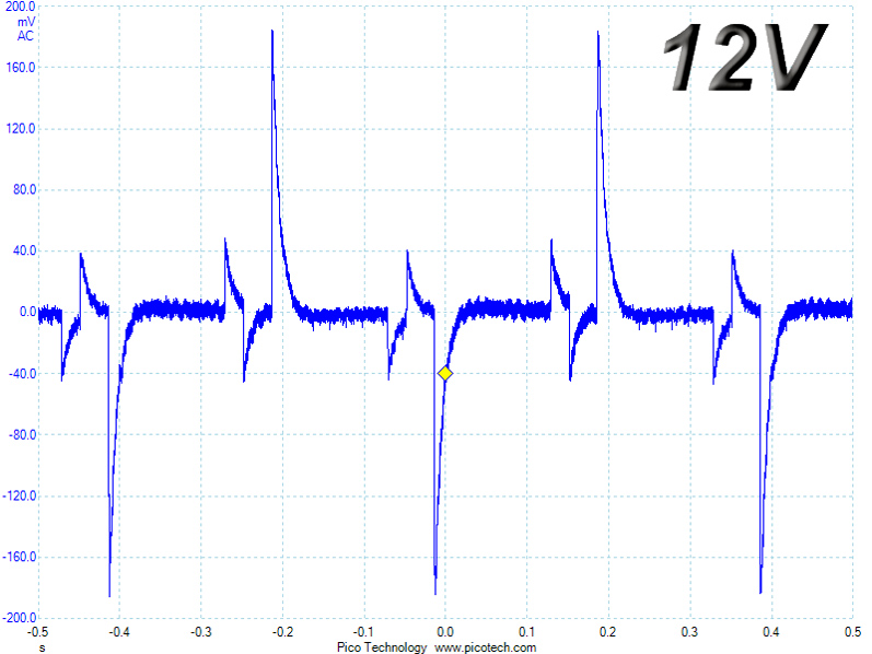
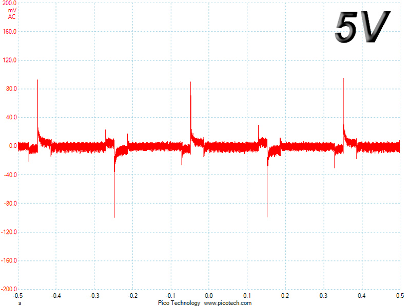
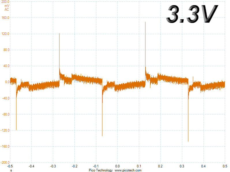
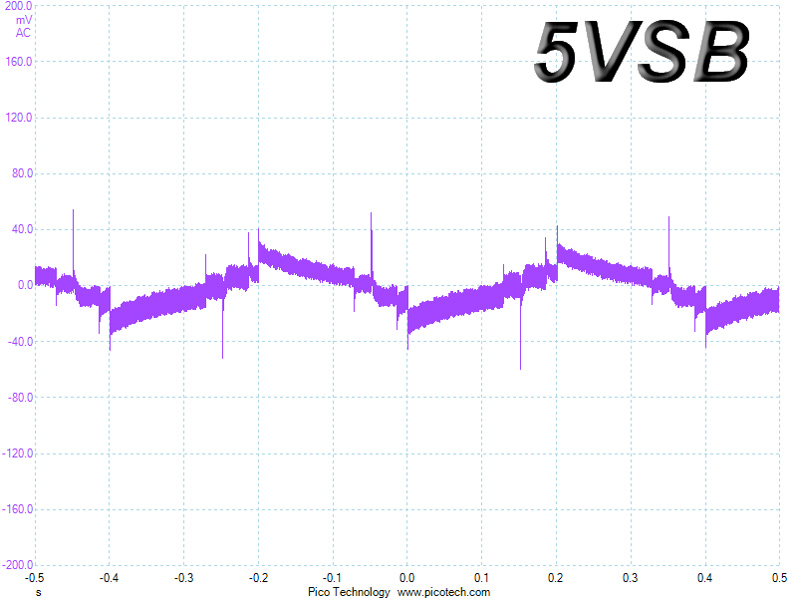
Due to the ACRF topology, we measured increased deviations in excess of 1% on the +12V rail. We do expect PSUs of similar capacity to deviate by no more than 1%, with close to 0.5% being excellent. The 3.3V rail also performed poorly in both tests since its voltage instantly dropped bellow 3.2 V once we applied the transient load.
Below are the oscilloscope screenshots we took during Advanced Transient Response testing.
Transient Response at 20% Load
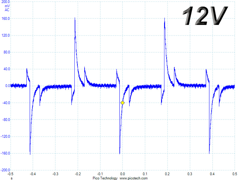
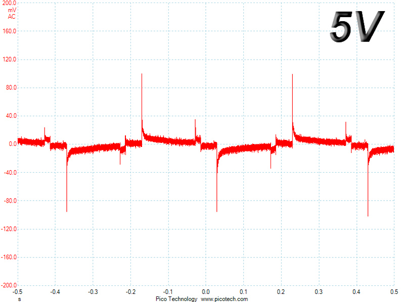
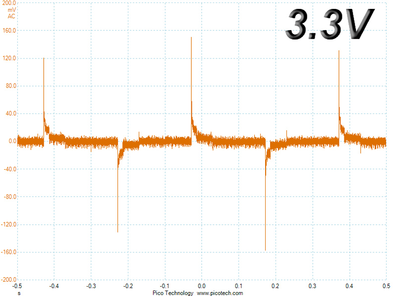
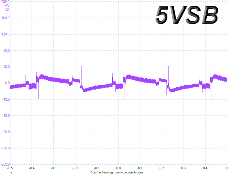
Transient Response at 50% Load
Turn-On Transient Tests
We measure the response of the PSU in simpler scenarios of transient load—during the power-on phase of the PSU—in the next set of tests. In the first test, we turn the PSU off, dial the maximum current the 5VSB can output, and then switch on the PSU. In the second test, we dial the maximum load +12V can handle and start the PSU while the PSU is in standby mode. In the last test, while the PSU is completely switched off (we cut off power or switch the PSU off by flipping its on/off switch), we dial the maximum load the +12V rail can handle before switching the PSU on from the loader and restoring power. The ATX specification states that recorded spikes on all rails should not exceed 10% of their nominal values (e.g., +10% for 12V is 13.2V and 5.5V for 5V).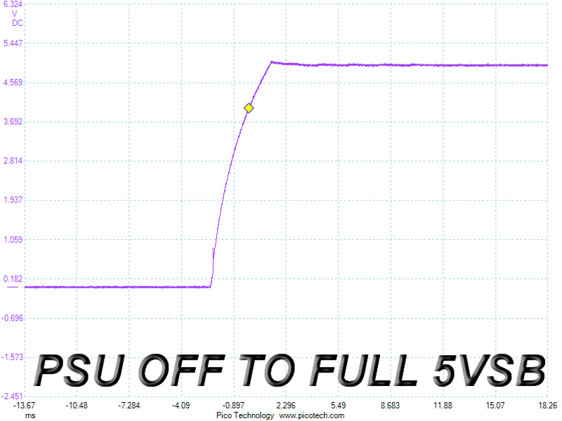
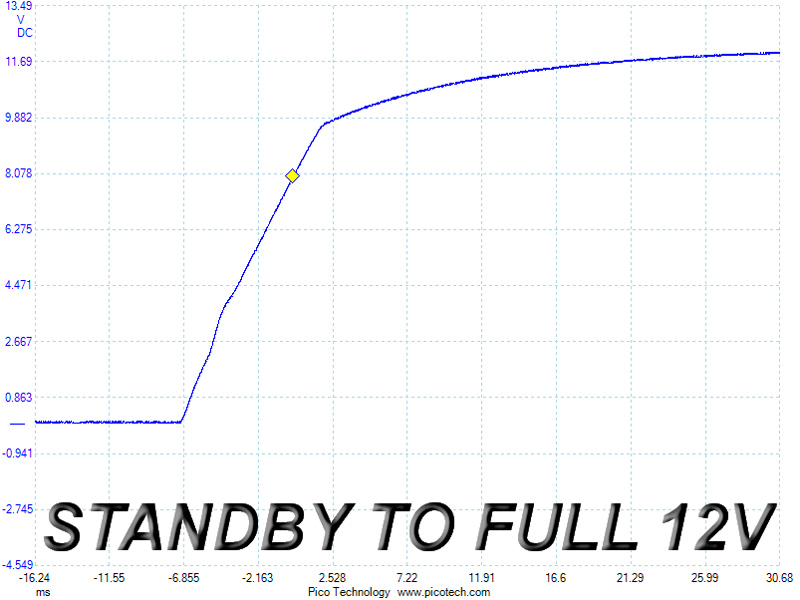
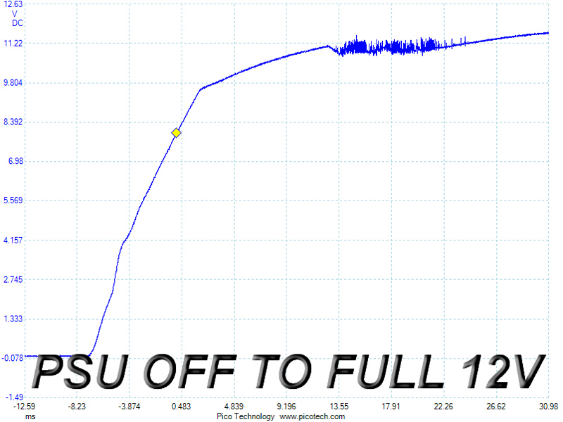
The PSU registered a very small voltage overshoot on its 5VSB rail, and while its slope was smooth in the second test, things didn't fare as well in the third test as ripple was out of control for a short period of time. The ACRF topology obviously couldn't handle the sudden full load during the unit's turn-on phase. Such is thankfully an unlikely real-life scenario since no PSU will be asked to deliver its full power right after it has been turned on; however, since the ATX specification includes the test, we will deduct some performance points for the result.
Feb 24th, 2025 06:58 EST
change timezone
Latest GPU Drivers
New Forum Posts
- Help choose M.2 Key E Wifi card (0)
- It's happening again, melting 12v high pwr connectors (908)
- Throw Noctua alternatives at me pls (3)
- RDNA4 Prediction Time Part Deux!!! (42)
- [Testers-Needed] Converting Any Realtek Ethernet to Intel Killer Ethernet chip (87)
- [Intel AX1xx/AX2xx/AX4xx/AX16xx/BE2xx/BE17xx] Intel Modded Wi-Fi Driver with Intel® Killer™ Features (277)
- Monitor Battle! Help me choose between two contenders (42)
- Warning about DOCP (18)
- help me find the right bios for my his RX580 Iceq2 X 8Gb (6)
- mV boost option greyed out/ CPU Cache isn't separated by P and E/Cinebench Crashing even with no undervolt (1)
Popular Reviews
- ASUS GeForce RTX 5070 Ti TUF OC Review
- MSI GeForce RTX 5070 Ti Ventus 3X OC Review
- darkFlash DY470 Review
- MSI GeForce RTX 5070 Ti Vanguard SOC Review
- MSI GeForce RTX 5070 Ti Gaming Trio OC+ Review
- Galax GeForce RTX 5070 Ti 1-Click OC White Review
- Palit GeForce RTX 5070 Ti GameRock OC Review
- Fantech Aria II Pro Review
- Gigabyte GeForce RTX 5090 Gaming OC Review
- AMD Ryzen 7 9800X3D Review - The Best Gaming Processor
Controversial News Posts
- NVIDIA GeForce RTX 5090 Spotted with Missing ROPs, NVIDIA Confirms the Issue, Multiple Vendors Affected, RTX 5070 Ti, Too (458)
- AMD Radeon 9070 XT Rumored to Outpace RTX 5070 Ti by Almost 15% (304)
- AMD Plans Aggressive Price Competition with Radeon RX 9000 Series (271)
- AMD Radeon RX 9070 and 9070 XT Listed On Amazon - One Buyer Snags a Unit (247)
- Edward Snowden Lashes Out at NVIDIA Over GeForce RTX 50 Pricing And Value (241)
- AMD Denies Radeon RX 9070 XT $899 USD Starting Price Point Rumors (239)
- NVIDIA Investigates GeForce RTX 50 Series "Blackwell" Black Screen and BSOD Issues (236)
- New Leak Reveals NVIDIA RTX 5080 Is Slower Than RTX 4090 (215)