 8
8
Chieftronic PowerPlay 1050 W Review
(8 Comments) »Introduction
We would like to thank Chieftronic for supplying the review sample.

Chieftronic is Chieftec's gaming sub-brand. Currently, its portfolio only lists two cases and two PSU lines. Their flagship PSU product is the PowerPlay 1050 W (GPU-1050FC). Not only is its capacity high, but it also features 80 PLUS Platinum and Cybenetics ETA-A and LAMBDA-Standard+ certifications. For its high capacity, overall noise output (35 dBA) is quite low. For the moment, this product is only available in the EU.
The GPU-1050FC uses a high-end platform from CWT (Channel Well Technology), which I have also seen in the Thermaltake Toughpower Grand RGB 1050 W and Toughpower iRGB PLUS 1200 W. This is a semi-digital platform where two MCUs control the entire primary side and part of the secondary side. The DC-DC converters that generate the minor rails use an analog PWM controller.
Specifications
| Features & Specifications | |
|---|---|
| Max. DC Output | 1050 Watt |
| PFC | Active PFC |
| Efficiency | 80 PLUS Platinum, ETA-A (90%–93%) |
| Noise | LAMBDA-S+ (35–40 dBA) |
| Modular | Yes (fully) |
| Intel C6/C7 Power State Support | Yes |
| Operating Temperature | 0–50 °C |
| Protections | Over Voltage Protection Under Voltage Protection Over Power Protection Over Temperature Protection Over Current Protection Short Circuit Protection |
| Cooling | 140 mm sleeve bearing fan (HA1425L12F-Z) |
| Semi-passive Operation | Yes (selectable) |
| Dimensions (W x H x D) | 150 mm x 85 mm x 160 mm |
| Weight | 1.95 kg (4.3 lb) |
| Compliance | ATX12V v2.31, EPS 2.92 |
| Warranty | 3 years |
| Price at Time of Review (incl. VAT) | €189.8 |
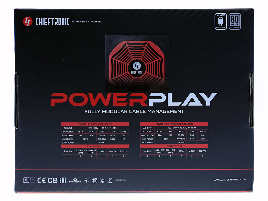
| Power Specifications | |||||||
|---|---|---|---|---|---|---|---|
| Rail | 3.3 V | 5 V | 12 V | 5 VSB | -12 V | ||
| Max. Power | 22 A | 22 A | 52 A | 3 A | 0.3 A | ||
| 120 W | 999.96 W | 15 W | 3.6 W | ||||
| Total Max. Power | 1050 W | ||||||
Photos
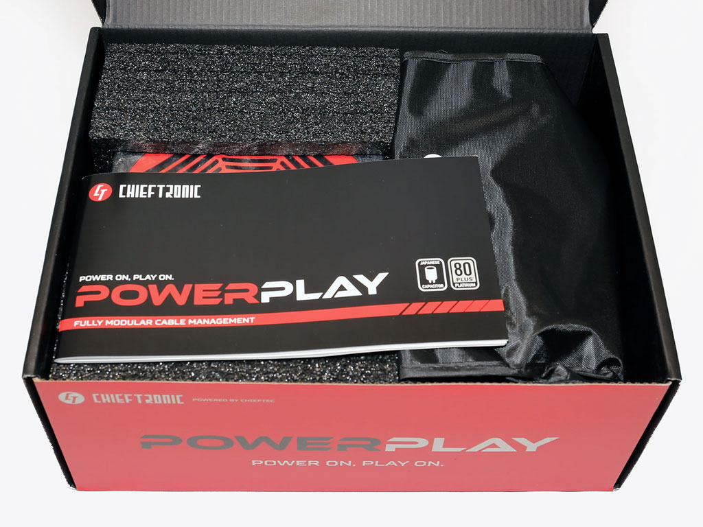
Protection inside the box is adequate since foam spacers cover the front and rear sides of the PSU. Typically, the first thing that greets you once you open the box is the user's manual.
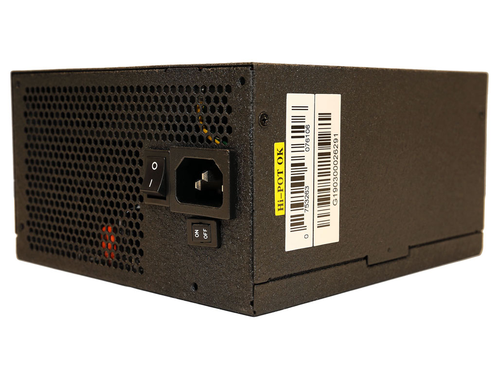
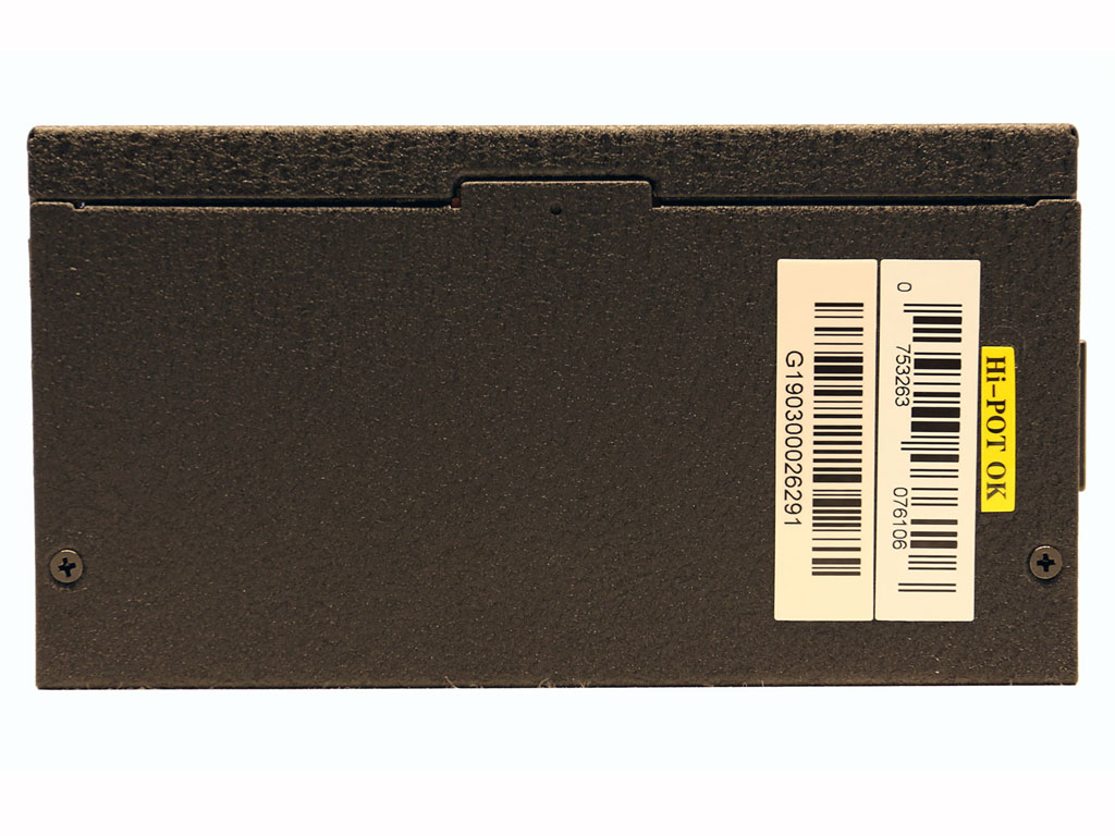
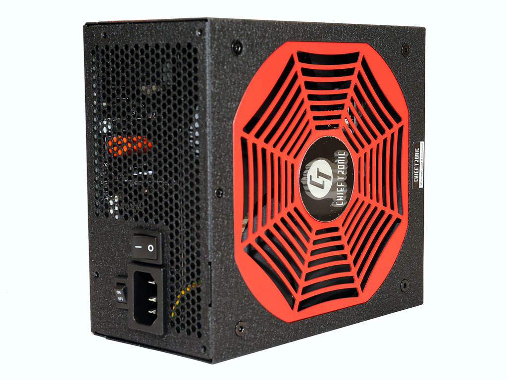
At the front are the power switch and one for toggling on or off the semi-passive operation.
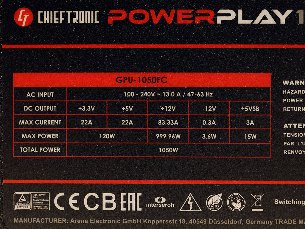
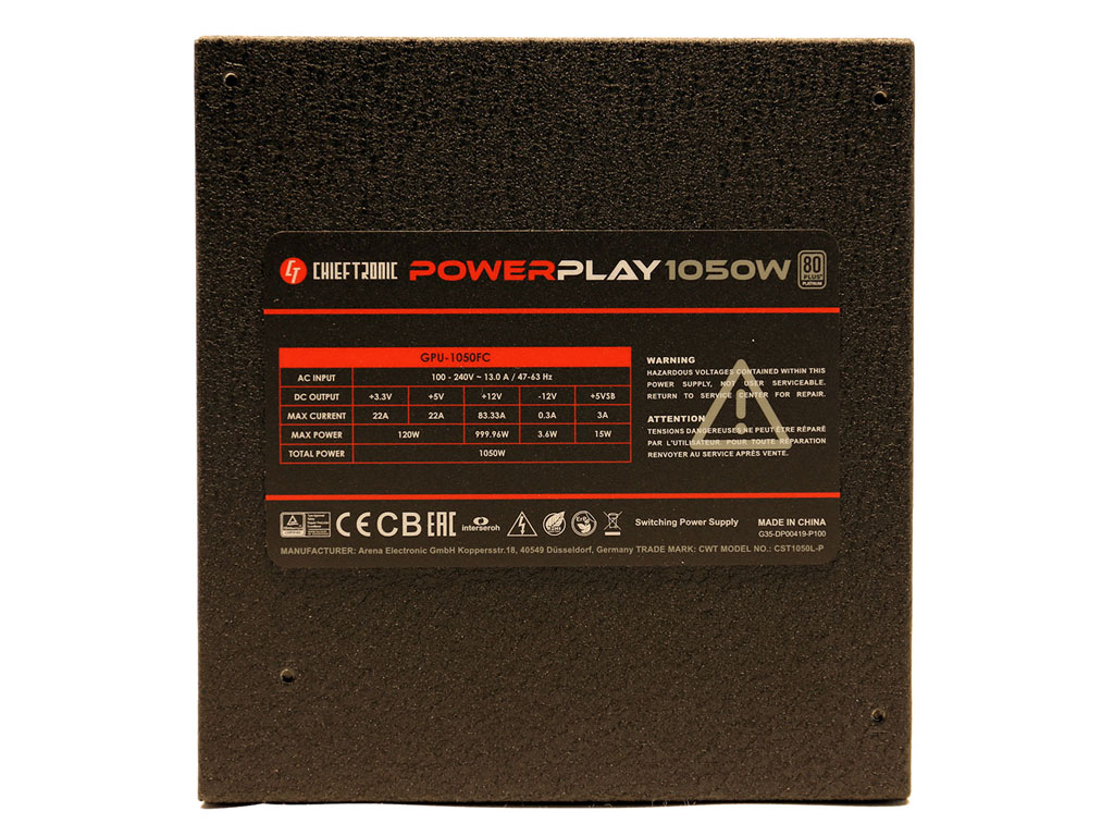
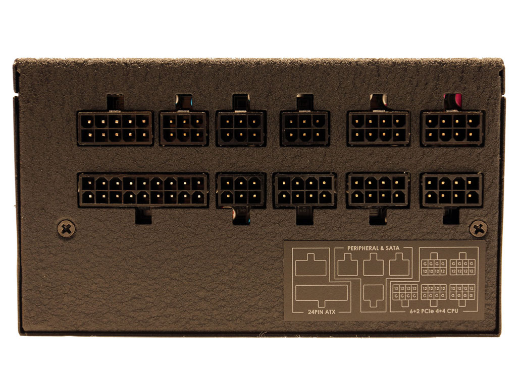
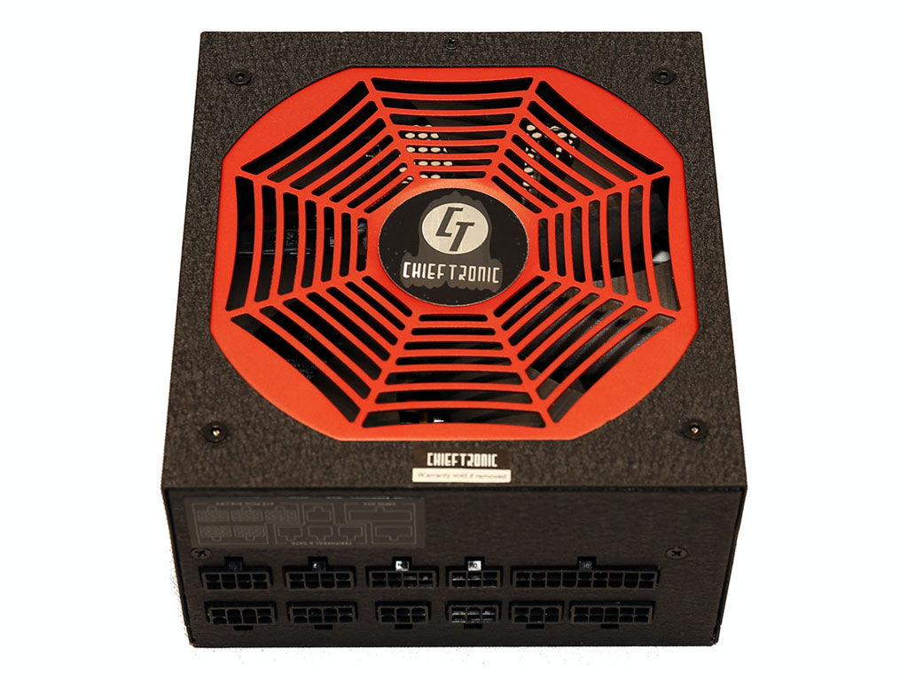
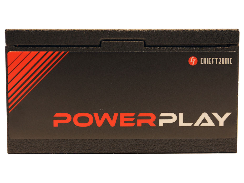
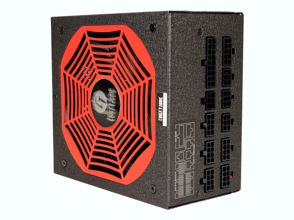
The specifications label is at the bottom. A small sticker around the back describes all modular sockets. You can connect the PCIe and EPS cables to every compatible socket since all are electrically compatible.
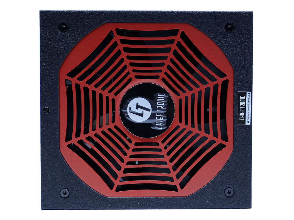
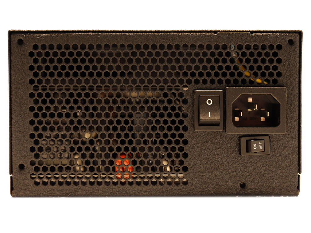
The fan grill looks like a spider's web, and I hate spiders!
Cables and Connectors
| Modular Cables | ||||
|---|---|---|---|---|
| Description | Cable Count | Connector Count (Total) | Gauge | In Cable Capacitors |
| ATX connector 20+4 pin (600 mm) | 1 | 1 | 16AWG | No |
| 8 pin EPS12V (600 mm) / 4+4 pin EPS12V (150 mm) | 1 | 1 / 1 | 16-18AWG | No |
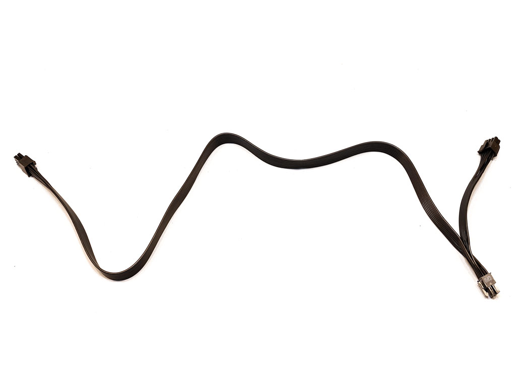
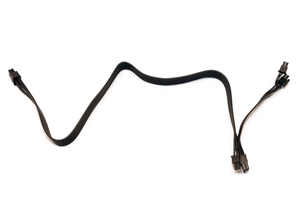
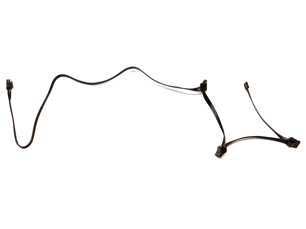
| 6+2 pin PCIe (600 mm+150 mm) | 4 | 8 | 16-18AWG | No |
| SATA (800 mm+150 mm+150 mm) | 3 | 9 | 18AWG | No |
| 4-pin Molex (700 mm+150 mm+150 mm) / FDD (+150 mm) | 1 | 3 / 1 | 18-20AWG | No |
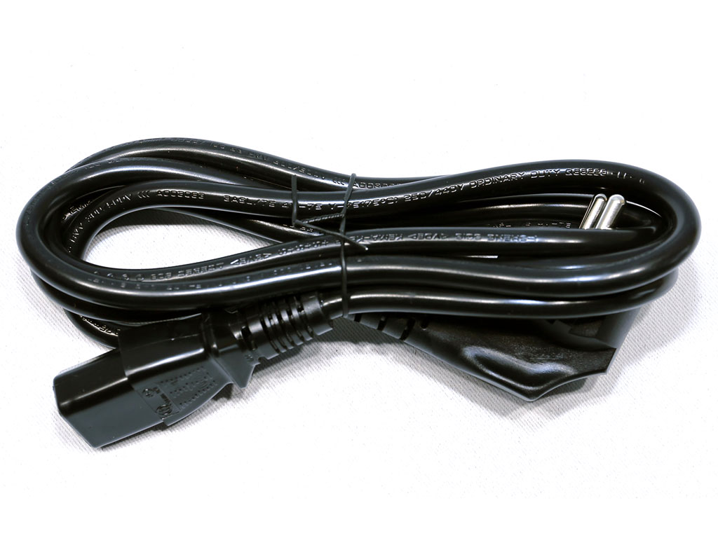
| AC Power Cord (1400 mm) - C13 coupler | 1 | 1 | 18AWG | - |
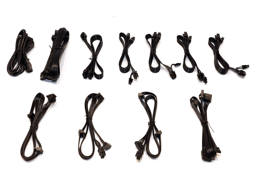
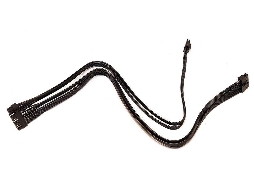
The cables are quite long. Still, more headroom up to the first EPS connector would have been nice. It is also a huge mistake to install both EPS connectors on the same cable, even with 16AWG gauges up to the first connector. The load an EPS connector can deliver is huge, so with both of these connectors on the same cable, the corresponding socket on the modular panel can easily melt, especially since this is a single +12 V rail PSU with the ability to deliver up to 52 A on the rail.
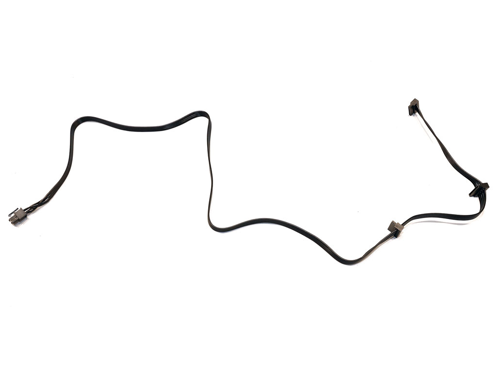
Six PCIe and two EPS connectors on dedicated cables would have been much better than the eight PCIe connectors and two EPS connectors on the same cable.
Component Analysis
Before reading this page, we strongly suggest a look at this article, which will help you understand a PSU's internals better.| Chieftronic GPU-1050FC Parts Description | |
|---|---|
| General Data | |
| Manufacturer (OEM) | CWT |
| PCB Type | Double-sided |
| Primary Side | |
| Transient Filter | 6x Y caps, 2x X caps, 2x CM chokes, 1x MOV |
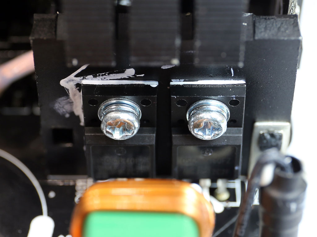
| Bridge Rectifier(s) | 2x GBJ2506P (600 V, 25 A @ 100 °C) |
| Inrush Current Protection | NTC Thermistor SCK-085 & Relay |
| APFC MOSFETs | |
| APFC Boost Diode | 2x ON Semiconductor FFSP0665A (650 V, 6 A @ 153 °C) |
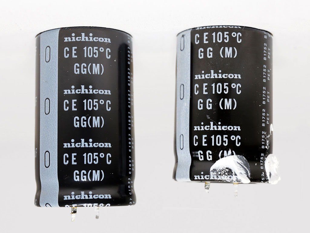
| Hold-up Cap(s) | 2x Nichicon (400 V, 680 uF & 560 uF each or 1,240 uF combined, 2,000 h @ 105 °C GG) |
| Main Switchers | 4x OSG55R160FZ |
| IC Drivers | 2x Silicon Labs Si8233BD |
| Digital Controllers | 2x Texas Instruments UCD3138A |
| Topology | Primary side: Semi-Digital, Interleaved PFC, full-bridge & LLC converter Secondary side: synchronous rectification & DC-DC converters |
| Secondary Side | |
| +12 V | 8x Infineon BSC014N06NS (60 V, 100 A @ 100 °C, 1.45 mOhm) |
| +5 V & +3.3 V | DC-DC Converters:4x UBIQ QM3006D (30 V, 57 A @ 100 °C, 5.5 mOhm) |
| Filtering Capacitors | |
| Supervisor IC | Weltrend WT7502 ( OVP, UVP, SCP, PG) |
| Fan Model | Hong Hua HA1425L12F-Z (140 mm, 12 V, 0.22 A, sleeve bearing fan) |
| 5VSB Circuit | |
| Rectifiers | 1X UTC 4N65L (650 V, 4 A, 2.5 ohm) & PS1045L SBR (45 V, 10 A) |
| Standby PWM Controller | On-Bright OB5282 |
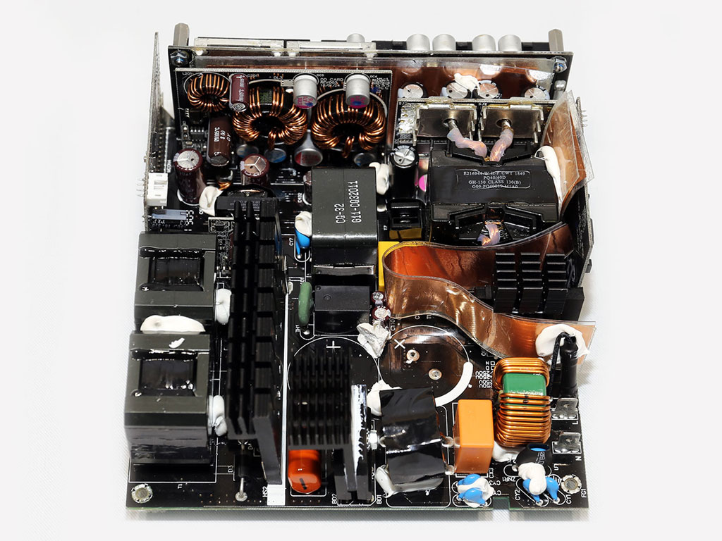


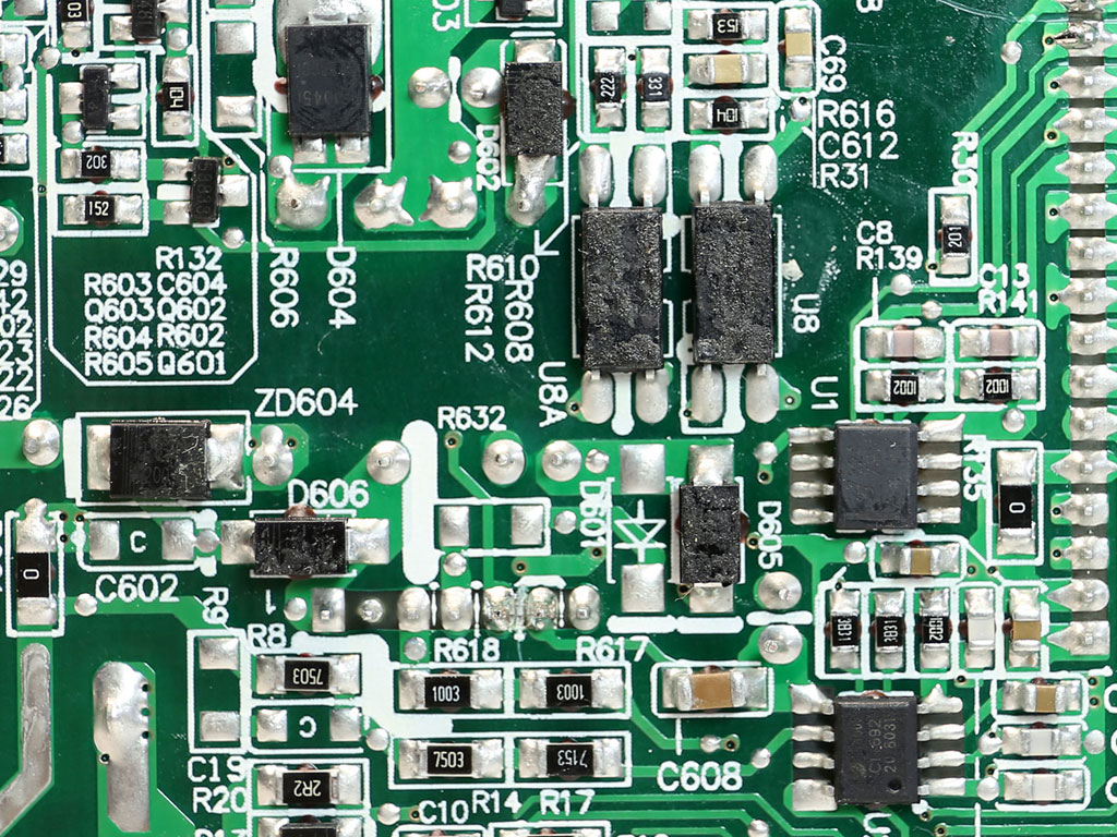
This is a high-end CWT semi-digital platform several expensive Thermaltake Toughpower PSUs also utilize. Because of its compact dimensions, the PCB is loaded with components, which means airflow is not optimal as there isn't much clearance between components. Still, CWT used small heatsinks, especially on the secondary side. The build quality is good, all electrolytic caps belong to good lines.
The EMI/transient filter has all the necessary components, but the digital circuits emit lots of EMI, which the EMI filter cannot handle.
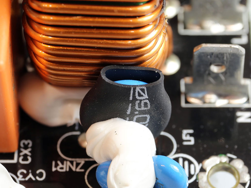
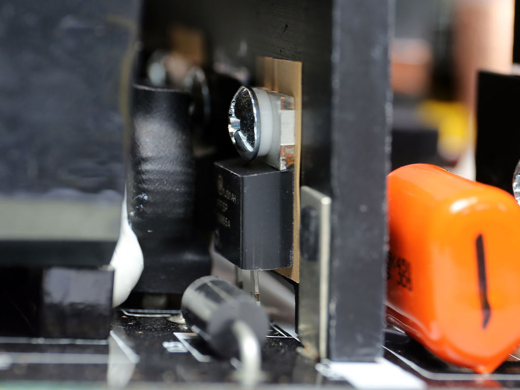
An MOV in the transient filter handles power surges, and an NTC thermistor and relay combo take care of the large inrush currents during the PSUs start-up phase.
Two bridge rectifiers are installed in parallel on a dedicated heatsink.

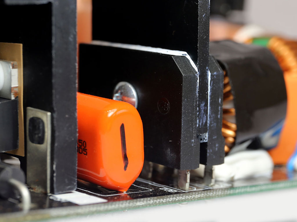
An interleaved APFC converter is used, with two PFC circuits operating in parallel with a phase difference between them. This minimizes input and output current ripple and lowers conduction losses, which increases efficiency and doubles the effective switching frequency.
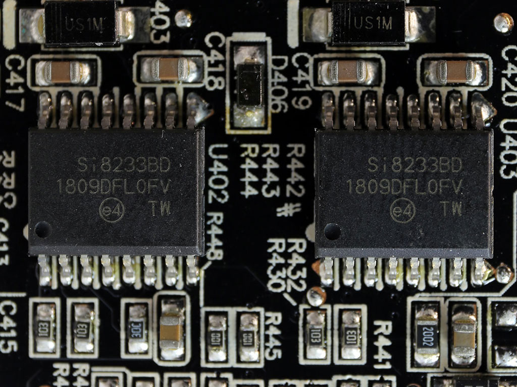
The four main switching FETs are installed in a full bridge topology. Two driver ICs are installed on the digital PCB. They are used for controlling the aforementioned FETs.
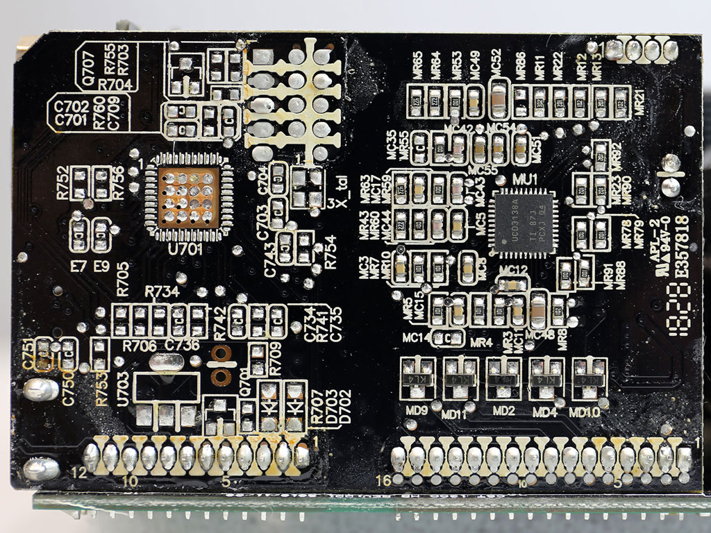
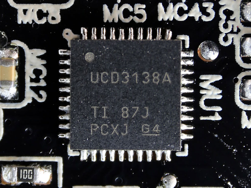
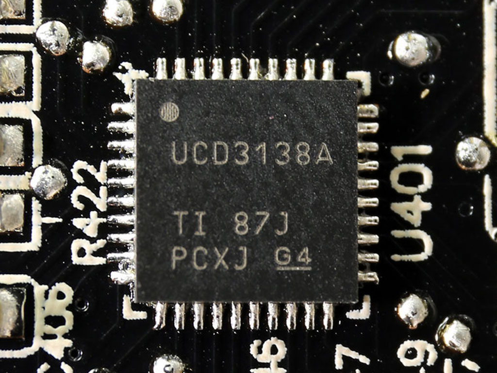
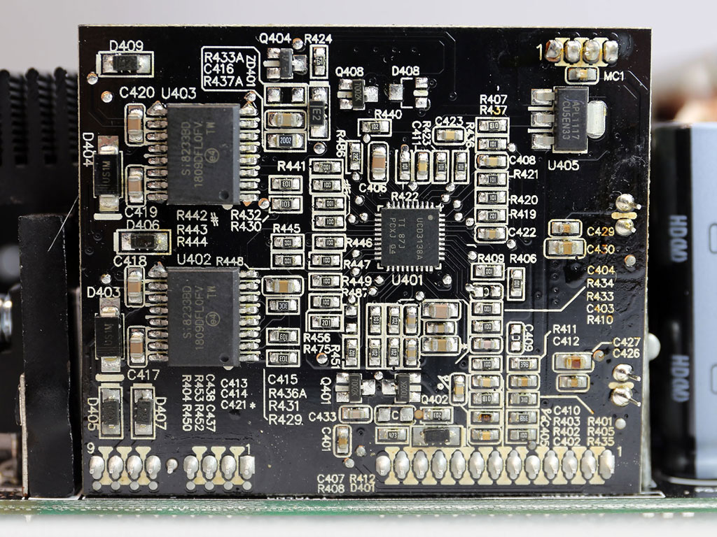
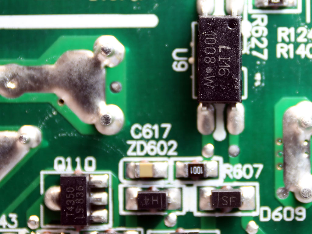
This is where the magic happens. Two Texas Instruments UCD3138A MCUs on this PCB take care of the whole primary side and the most important part of the secondary side, which is the circuit that generates the +12 V rail.
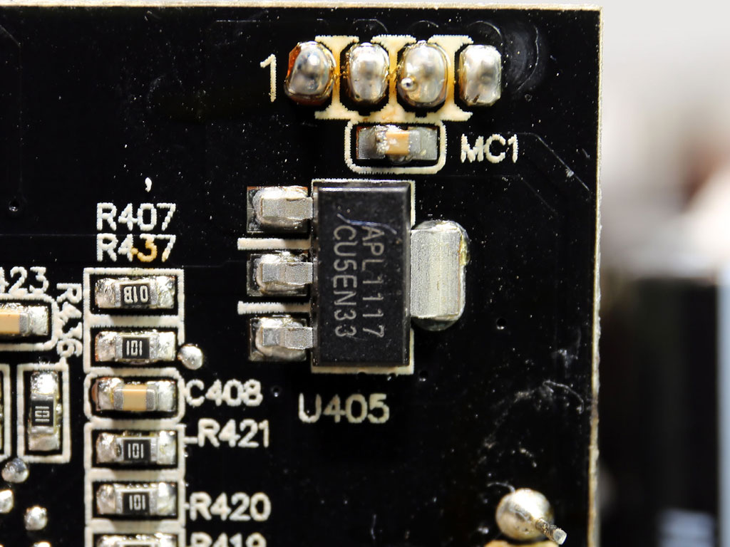
An APL1117 voltage regulator with 1 A max output. It most likely provides the operating voltage to the two MCUs.
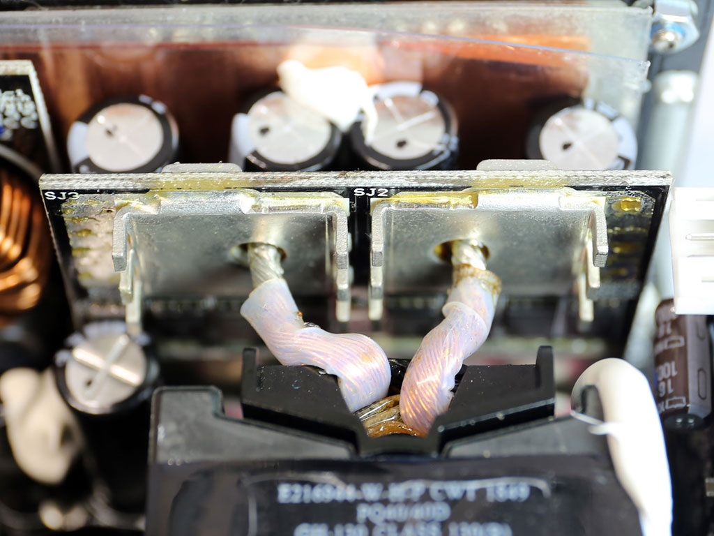
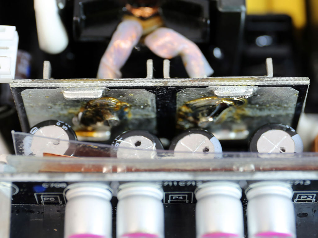
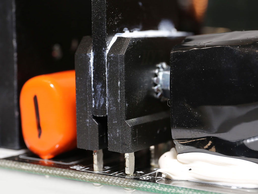
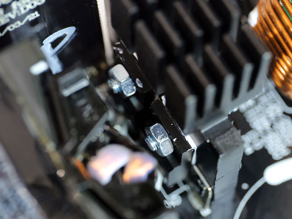
The board that hosts the +12 V FETs is right next to the main transformer, and two thick, ultra-short cables are used for its connection to minimize energy losses. The heatsinks on this board are small, but the corresponding FETs can operate at high temperatures without any problems.
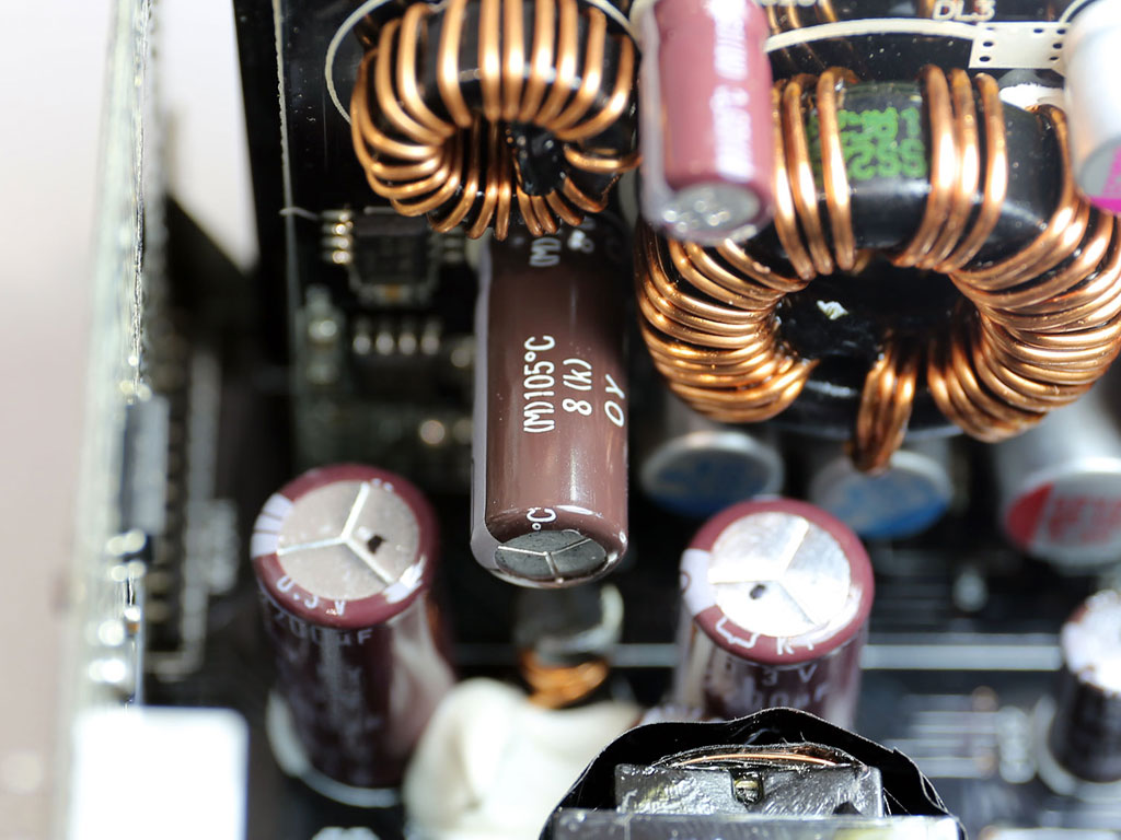
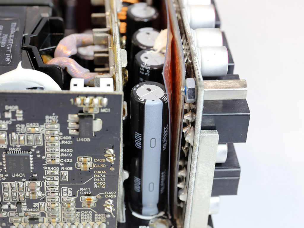
The filtering caps are of high quality, but they are squeezed between the modular PCB and the +12 V board, so the fan will have to spin at high speeds with high loads in order to keep their temperature low enough.
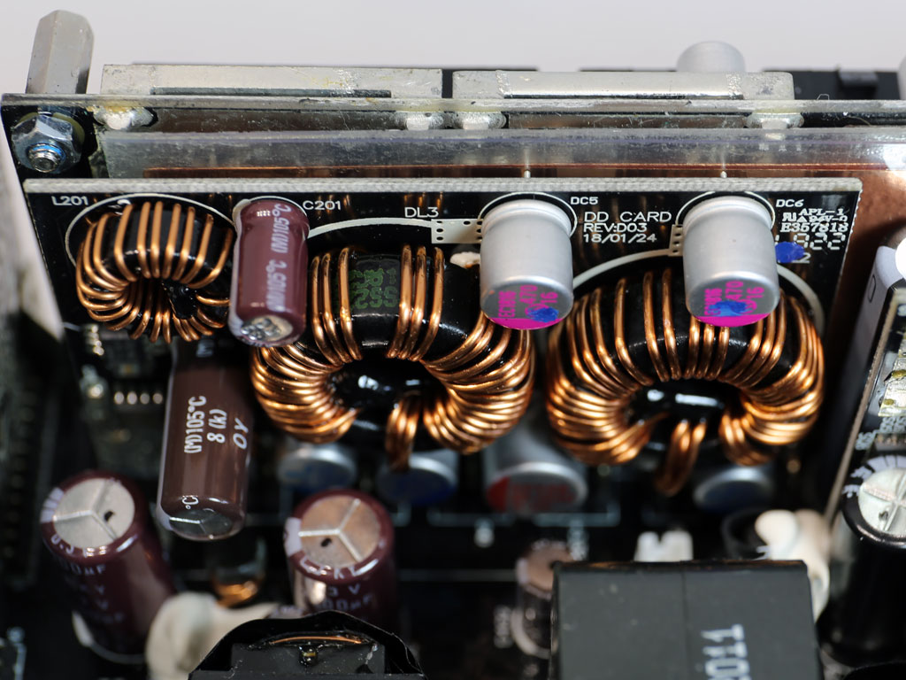
Both VRMs that handle the minor rails are installed on this board.
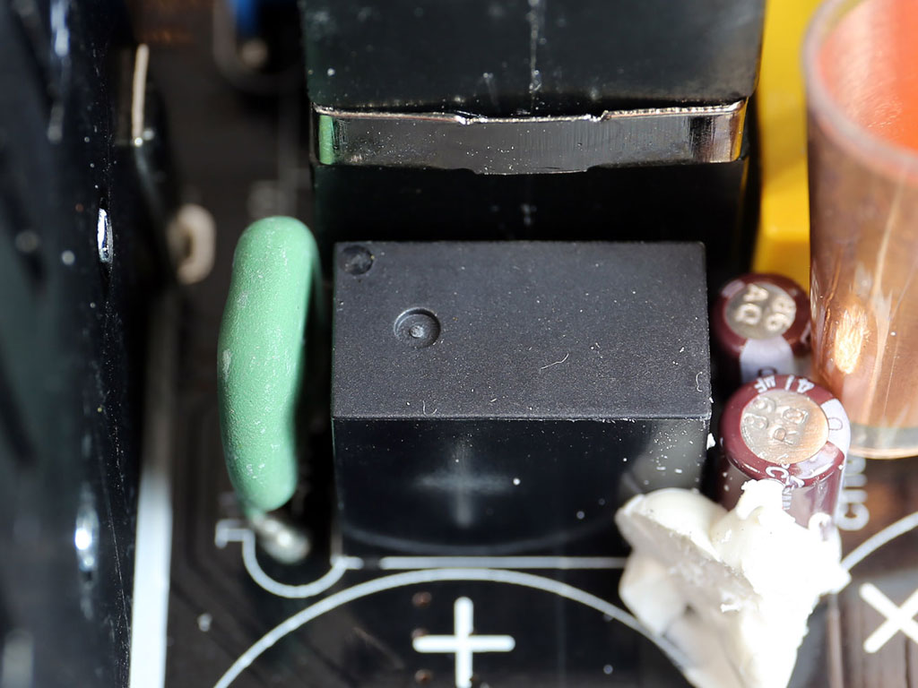
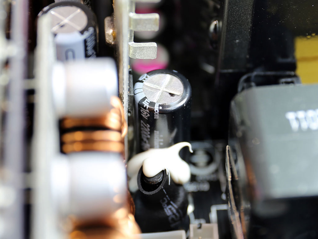
The 5VSB transformer and, right next to it, a vertical board that hosts the other parts of this circuit.

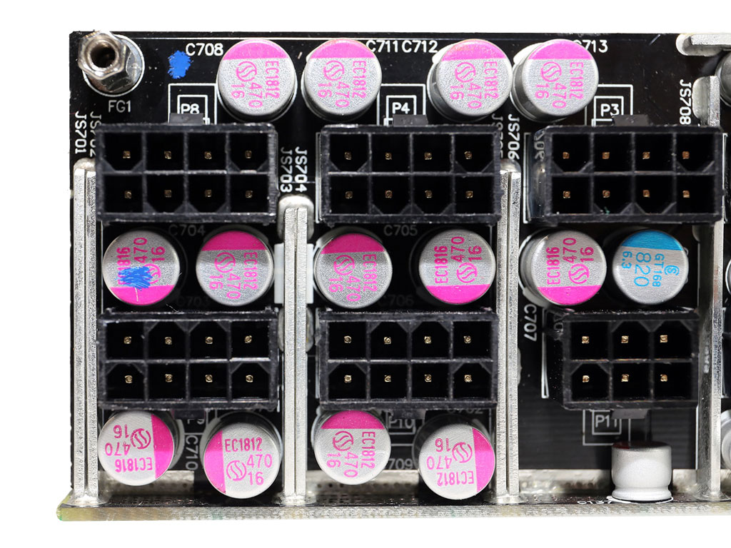
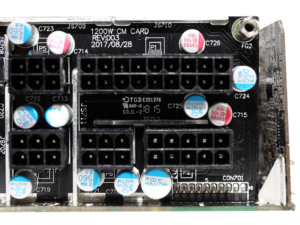
Lots of polymer caps have been installed on the modular board.
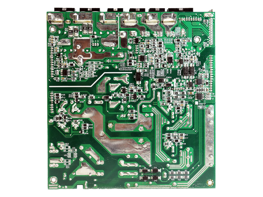

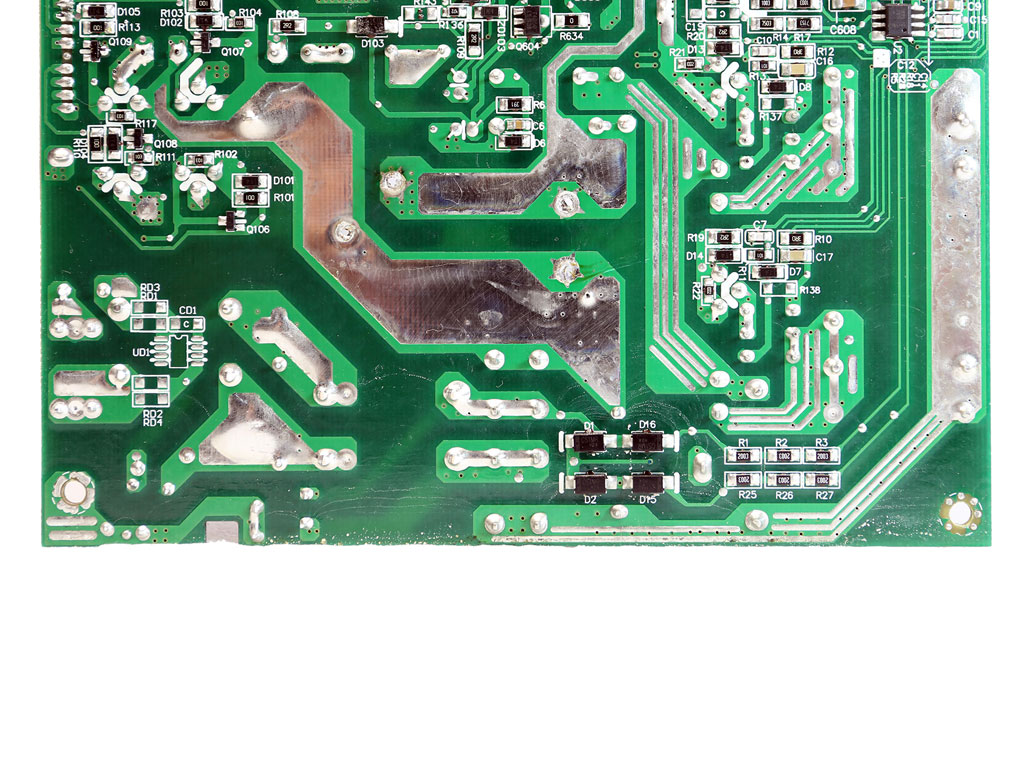
Soldering quality is pretty good, which is usually the case with high-end CWT implementations.
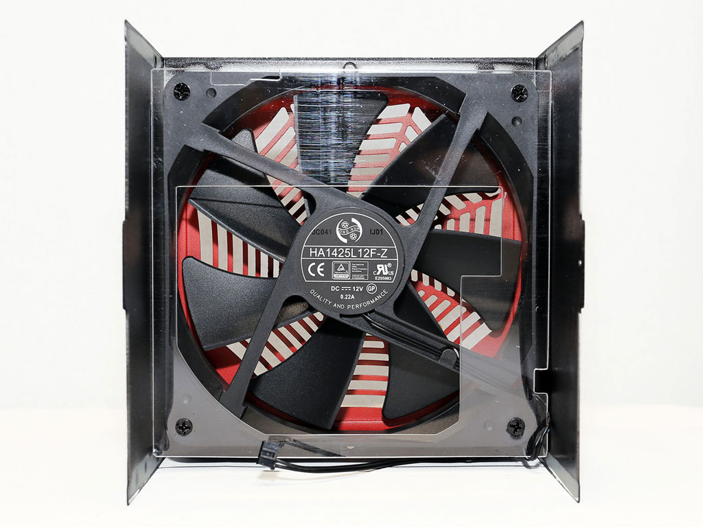

The Hong Hua fans are very popular because they offer good performance and reliability for a good price, which has most manufacturers prefer them.
Our Patreon Silver Supporters can read articles in single-page format.
May 4th, 2025 21:08 EDT
change timezone
Latest GPU Drivers
New Forum Posts
- Are the 8 GB cards worth it? (837)
- Best USB 3 hub chipsets (18)
- Half Life 3 soon ? (12)
- RX 9000 series GPU Owners Club (636)
- is it possible to buy a sata to propietary dell pata adapter? (1)
- 12600KF high latency (24)
- The TPU Darkroom - Digital SLR and Photography Club (4085)
- 245KF e-cores running full clock after update (5)
- Vertical mice in gaming (11)
- The TPU UK Clubhouse (26194)
Popular Reviews
- ASUS ROG Maximus Z890 Hero Review
- ASUS Radeon RX 9070 XT TUF OC Review
- Clair Obscur: Expedition 33 Performance Benchmark Review - 33 GPUs Tested
- Montech HS02 PRO Review
- NVIDIA GeForce RTX 5060 Ti 8 GB Review - So Many Compromises
- Seasonic Vertex GX 850 W Review
- Upcoming Hardware Launches 2025 (Updated Apr 2025)
- ASUS GeForce RTX 5090 Astral Liquid OC Review - The Most Expensive GPU I've Ever Tested
- Sapphire Radeon RX 9070 XT Nitro+ Review - Beating NVIDIA
- AMD Ryzen 7 9800X3D Review - The Best Gaming Processor
Controversial News Posts
- AMD Radeon RX 9060 XT to Roll Out 8 GB GDDR6 Edition, Despite Rumors (129)
- NVIDIA Sends MSRP Numbers to Partners: GeForce RTX 5060 Ti 8 GB at $379, RTX 5060 Ti 16 GB at $429 (128)
- NVIDIA Launches GeForce RTX 5060 Series, Beginning with RTX 5060 Ti This Week (115)
- Nintendo Confirms That Switch 2 Joy-Cons Will Not Utilize Hall Effect Stick Technology (105)
- NVIDIA PhysX and Flow Made Fully Open-Source (95)
- Sony Increases the PS5 Pricing in EMEA and ANZ by Around 25 Percent (84)
- Parts of NVIDIA GeForce RTX 50 Series GPU PCB Reach Over 100°C: Report (78)
- Intel "Bartlett Lake-S" Gaming CPU is Possible, More Hints Appear for a 12 P-Core SKU (77)