 5
5
Corsair AX Series 760 W Review
Ripple Measurements »Advanced Transient Response Tests
In these tests, we monitor the response of the PSU in two different scenarios. First, a transient load (10 A at +12V, 5 A at 5V, 5 A at 3.3V, and 0.5 A at 5VSB) is applied to the PSU for 200 ms while the latter is working at a 20% load state. In the second scenario, the PSU, while working at 50% load, is hit by the same transient load. In both tests, we measure the voltage drops that the transient load causes using our oscilloscope. The voltages should remain within the regulation limits defined by the ATX specification. We must stress that the above tests are crucial since they simulate transient loads that a PSU is very likely to handle (e.g., booting a RAID array, an instant 100% load of CPU/VGAs, etc.) We call these tests "Advanced Transient Response Tests", and they are designed to be very tough to master, especially for PSUs with capacities lower than 500 W.| Advanced Transient Response 20% | ||||
|---|---|---|---|---|
| Voltage | Before | After | Change | Pass/Fail |
| 12 V | 12.106V | 12.032V | 0.61% | Pass |
| 5 V | 5.032V | 4.954V | 1.55% | Pass |
| 3.3 V | 3.342V | 3.217V | 3.74% | Pass |
| 5VSB | 5.077V | 5.051V | 0.51% | Pass |
| Advanced Transient Response 50% | ||||
|---|---|---|---|---|
| Voltage | Before | After | Change | Pass/Fail |
| 12 V | 12.076V | 12.003V | 0.60% | Pass |
| 5 V | 5.025V | 4.975V | 1.00% | Pass |
| 3.3 V | 3.336V | 3.209V | 3.81% | Pass |
| 5VSB | 5.044V | 5.009V | 0.69% | Pass |
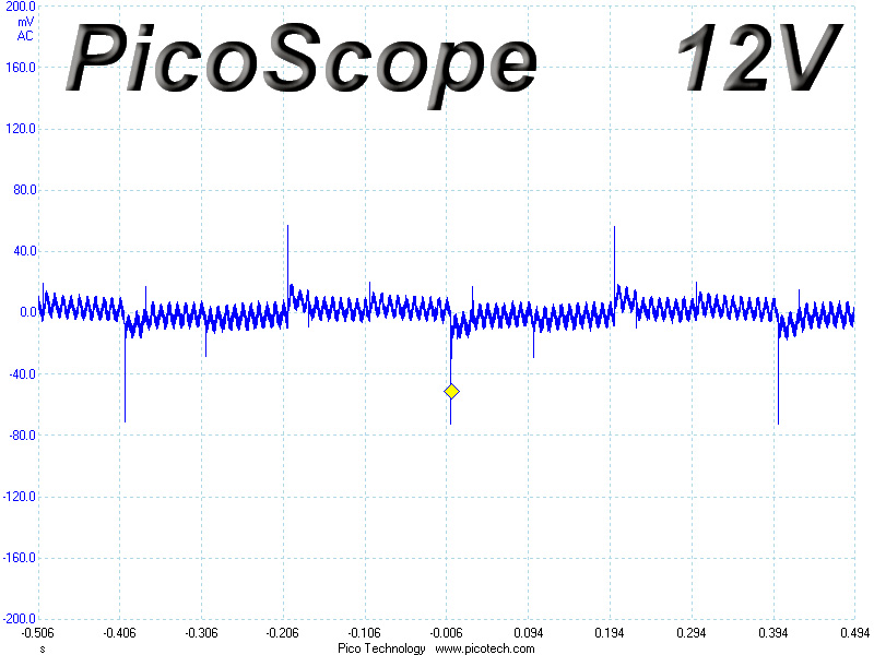
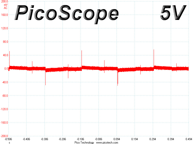
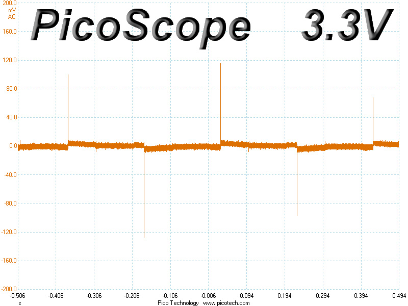
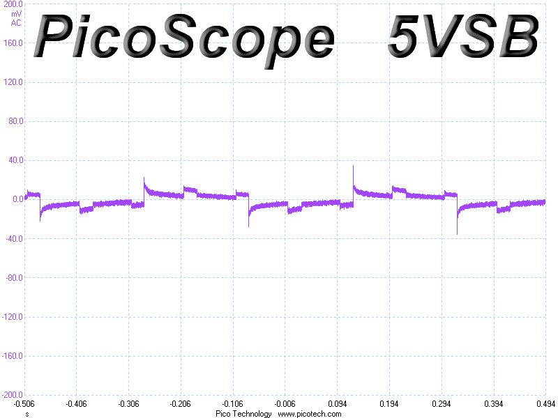
The deviations of the +12V rail, which is the most important rail of all, are minimal on both tests. The 5V and 5VSB rails also registered low voltage drops. The 3.3V rail registered the highest deviations, but it still managed to keep its voltage above 3.2 V on all tests.
Below, you will find the oscilloscope screenshots that we took during Advanced Transient Response Testing.
Transient Response at 20% Load
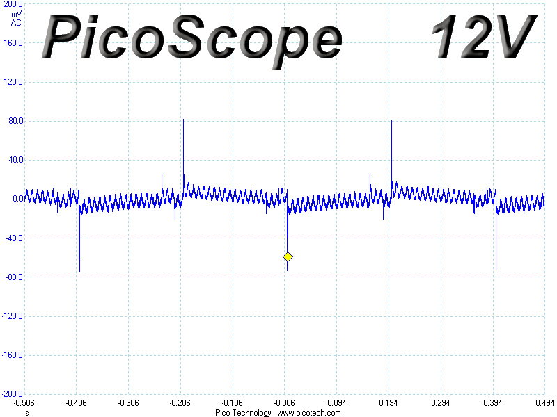
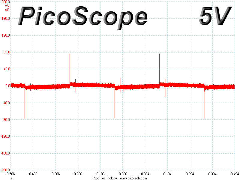
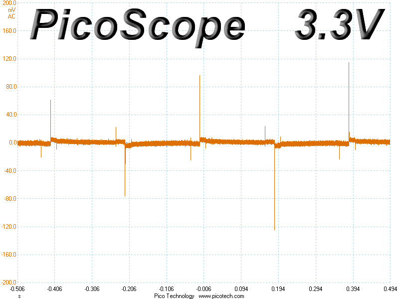
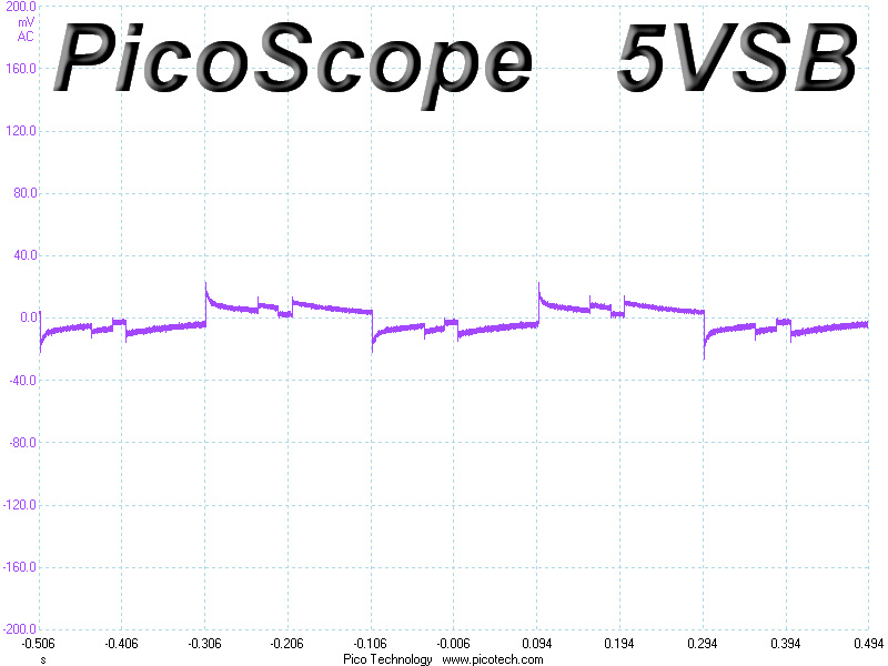
Transient Response at 50% Load
Turn-On Transient Tests
We measure the response of the PSU in simpler scenarios of transient loads – during the power-on phase of the PSU – in the next set of tests. In the first test, we turn the PSU off, dial the maximum current that the 5VSB can output, and then switch on the PSU. In the second test, we dial the maximum load that +12V can handle and we start the PSU, all while the PSU is in standby mode. In the last test, while the PSU is completely switched off (we cut off power or switch off the PSU's on/off switch), we dial the maximum load that the +12V rail can handle before switching the PSU on from the loader and restoring power. The ATX specification states that recorded spikes on all rails should not exceed 10% of their nominal values (e.g., +10% for 12V is 13.2V and for 5V is 5.5V).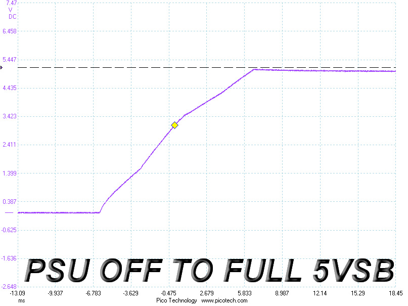
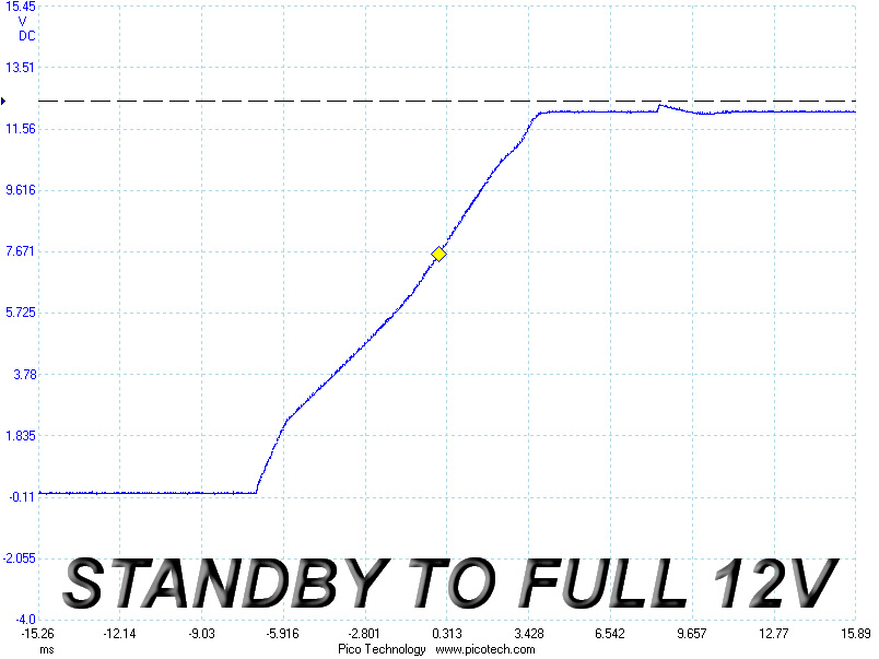
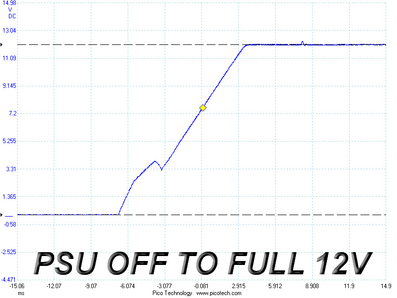
Voltage overshoot is minimal at 5VSB, but we noticed a couple weird spikes that occurred after the voltage settled down during the other two tests. Spikes during turn on are normally registered before voltages stabilize to their nominal levels, but the behavior was totally different in this case. Also, the last test registered a small dive at around 4V before the slope followed a rising path. The slope should ideally ramp up smoothly and continuously.
Feb 9th, 2025 19:12 EST
change timezone
Latest GPU Drivers
New Forum Posts
- It's happening again, melting 12v high pwr connectors (29)
- Which of the following gpus is better? (2)
- RTX5000 Series Owners Club (83)
- Ram tuning for 3700x. H16C memory (21)
- Black Screen Issue on Biostar RX 6700 XT – BIOS and Overclocking Concerns (1)
- Randoms BSOD during normal use or when I shut down the pc (1)
- Mind If I Play Through? (0)
- Asteroid 2024 YR4 reaches level 3 on the Torino Scale (4)
- Free Games Thread (4440)
- Last game you purchased? (675)
Popular Reviews
- Kingdom Come Deliverance II Performance Benchmark Review - 35 GPUs Tested
- Civilization VII Performance Benchmark Review - 35 GPUs Tested
- ASRock Phantom Gaming B850I Lightning Wi-Fi Review
- Spider-Man 2 Performance Benchmark Review - 35 GPUs Tested
- NVIDIA GeForce RTX 5080 Founders Edition Review
- Kingdom Come: Deliverance 2 Handheld Performance Review
- AMD Ryzen 7 9800X3D Review - The Best Gaming Processor
- Formovie Cinema Edge 4K UST Laser Projector Review
- ASUS ROG Harpe Ace Extreme Review
- Corsair Frame 4000D Review
Controversial News Posts
- AMD Radeon 9070 XT Rumored to Outpace RTX 5070 Ti by Almost 15% (286)
- AMD is Taking Time with Radeon RX 9000 to Optimize Software and FSR 4 (256)
- AMD Denies Radeon RX 9070 XT $899 USD Starting Price Point Rumors (239)
- Edward Snowden Lashes Out at NVIDIA Over GeForce RTX 50 Pricing And Value (235)
- AMD Radeon RX 9070 XT & RX 9070 Custom Models In Stock at European Stores (226)
- New Leak Reveals NVIDIA RTX 5080 Is Slower Than RTX 4090 (215)
- AMD's Radeon RX 9070 Launch Faces Pricing Hurdles (175)
- AMD Radeon RX 9070 XT Tested in Cyberpunk 2077 and Black Myth: Wukong (169)