 14
14
Corsair AX860i 860 W Review
Ripple Measurements »Advanced Transient Response Tests
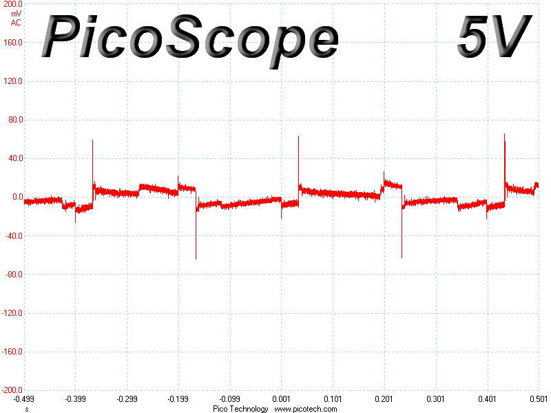
In these tests, we monitor the response of the PSU in two different scenarios. First, a transient load (10 A at +12V, 5 A at 5V, 5 A at 3.3V, and 0.5 A at 5VSB) is applied to the PSU for 200 ms while the latter is working at a 20% load state. In the second scenario, the PSU, while working at 50% load, is hit by the same transient load. In both tests, we measure the voltage drops that the transient load causes using our oscilloscope. The voltages should remain within the regulation limits defined by the ATX specification. We must stress here that the above tests are crucial since they simulate transient loads that a PSU is very likely to handle (e.g., booting a RAID array, an instant 100% load of CPU/VGAs, etc.) We call these tests "Advanced Transient Response Tests", and they are designed to be very tough to master, especially for PSUs with capacities lower than 500 W.| Advanced Transient Response 20% | ||||
|---|---|---|---|---|
| Voltage | Before | After | Change | Pass/Fail |
| 12 V | 12.026V | 11.926V | 0.83% | Pass |
| 5 V | 5.039V | 4.975V | 1.27% | Pass |
| 3.3 V | 3.320V | 3.223V | 2.92% | Pass |
| 5VSB | 5.017V | 4.956V | 1.22% | Pass |
| Advanced Transient Response 50% | ||||
|---|---|---|---|---|
| Voltage | Before | After | Change | Pass/Fail |
| 12 V | 12.023V | 11.928V | 0.79% | Pass |
| 5 V | 5.037V | 4.970V | 1.33% | Pass |
| 3.3 V | 3.307V | 3.217V | 2.72% | Pass |
| 5VSB | 5.006V | 4.961V | 0.90% | Pass |
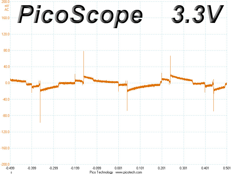
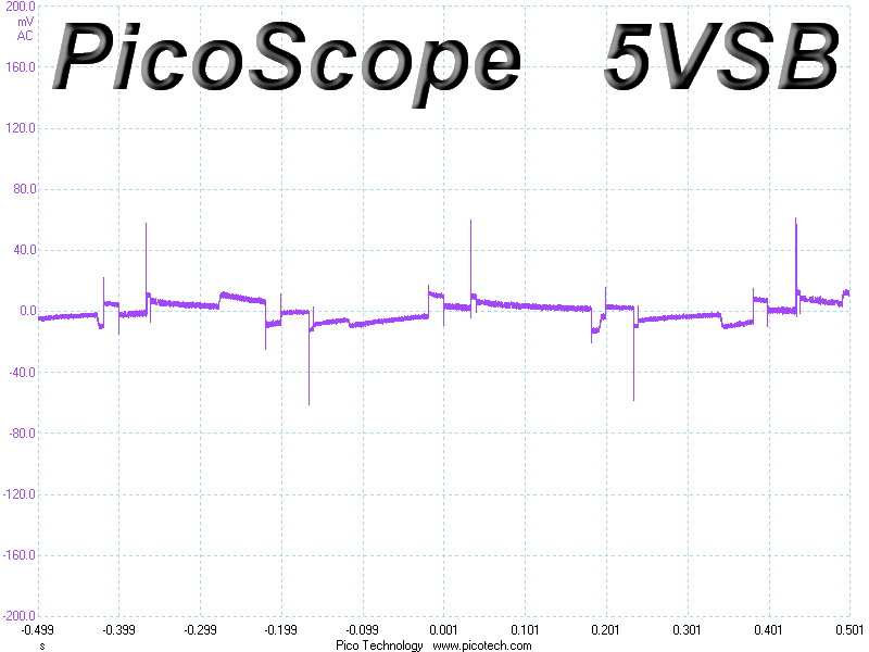
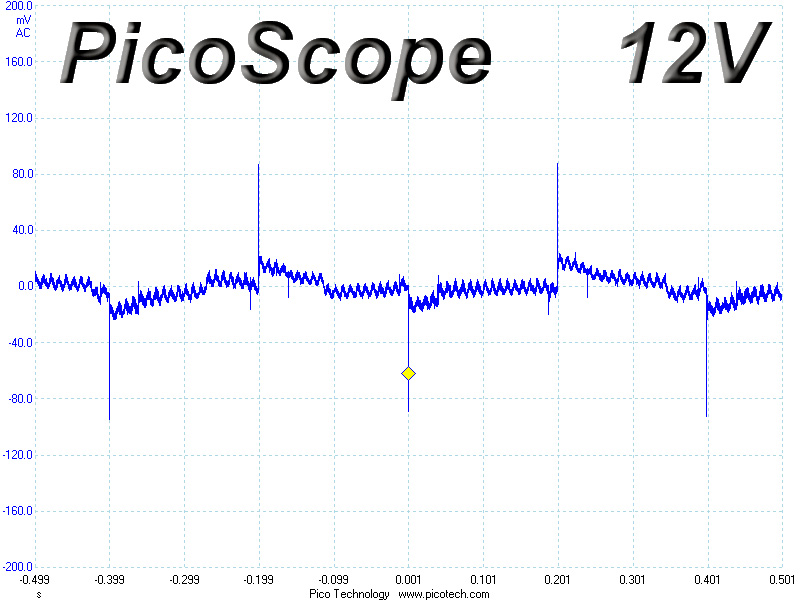
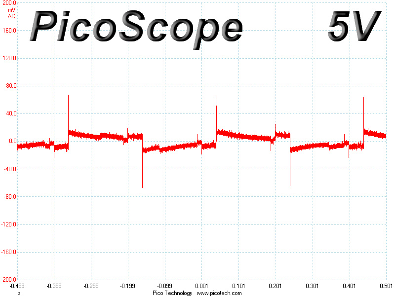
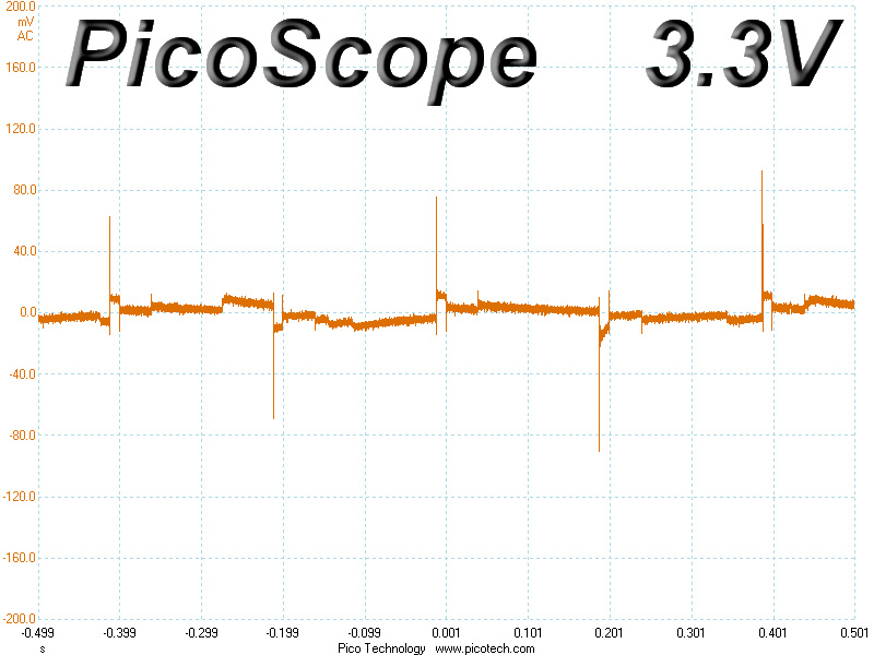
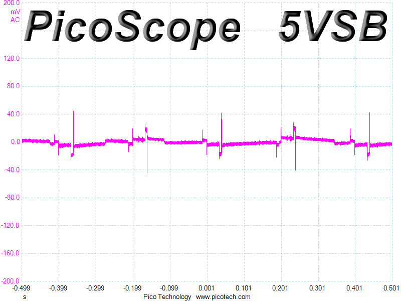
Voltage drops on all rails, especially at +12V, 5V and 5VSB, are well controlled, and all deviations are within 3%. The 3.3V rail has the larger deviation, but still manages to keep its voltage above 3.2 V. All in all, the AX860i handles dynamic loads pretty well and won't have any problems handling even extreme real-life scenarios.
Below, you will find the oscilloscope screenshots that we took during Advanced Transient Response Testing.
Transient Response at 20% Load

Transient Response at 50% Load
Turn-On Transient Tests
We measure the response of the PSU in simpler scenarios of transient loads - during the power-on phase of the PSU - in the next set of tests. In the first test, we turn the PSU off, dial the maximum current that the 5VSB can output, and then switch on the PSU. In the second test, we dial the maximum load that +12V can handle and we start the PSU, all while the PSU is in standby mode. In the last test, while the PSU is completely switched off (we cut off power or switch off the PSU's on/off switch), we dial the maximum load that the +12V rail can handle before switching the PSU on from the loader and restoring power. The ATX specification states that recorded spikes on all rails should not exceed 10% of their nominal values (e.g., +10% for 12V is 13.2V and for 5V is 5.5V).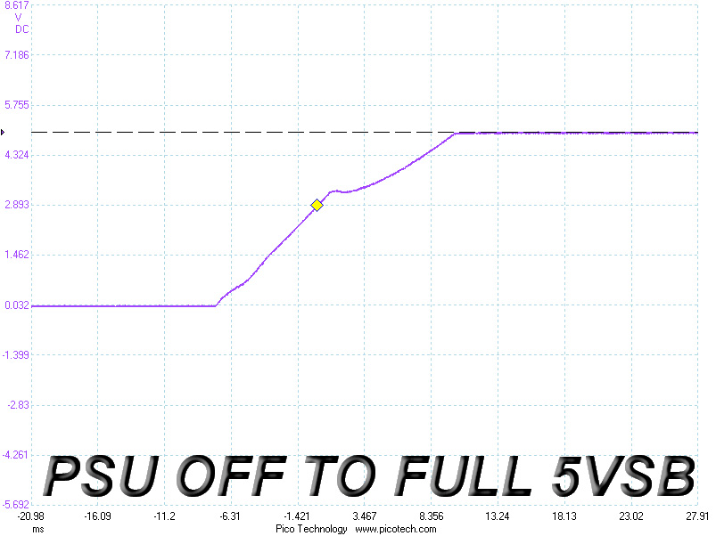
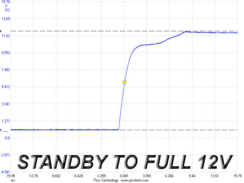
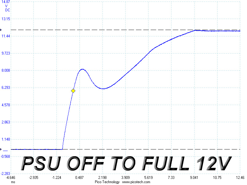
We didn't notice any voltage overshoots on the 5VSB rail, and the rise time is within the specified range (0.2-20 ms). There were small spikes at +12V in both cases, but they are nothing to be worried about since they were below 0.1 V. The slope on the last test did, on the other hand, register a large dive at around 8 V, something that we also noticed with the AX760i. Thankfully, this scenario is far from realistic, so it won't affect your system in real life.
Mar 12th, 2025 02:08 EDT
change timezone
Latest GPU Drivers
New Forum Posts
- RX 9070 availability (190)
- Post your Old CDs & FDs, from back in the day thread. (53)
- How's your old spinner holding up? (41)
- Cant Enable Resizable Bar (3)
- What are you playing? (23135)
- Nvidia's GPU market share hits 90% in Q4 2024 (gets closer to full monopoly) (852)
- intel 1700 with high speed ram,memory (51)
- Mismatched Memory Speeds for upcoming CPU Reviews? (98)
- Packet Loss after updating to windows 11 (3)
- Looking for suggestions on a vertical gaming mouse? (2)
Popular Reviews
- XFX Radeon RX 9070 XT Mercury OC Magnetic Air Review
- AMD Ryzen 9 9950X3D Review - Great for Gaming and Productivity
- Sapphire Radeon RX 9070 XT Nitro+ Review - Beating NVIDIA
- ASUS Radeon RX 9070 TUF OC Review
- MSI MAG B850 Tomahawk Max Wi-Fi Review
- AMD Ryzen 7 9800X3D Review - The Best Gaming Processor
- NVIDIA GeForce RTX 5070 Founders Edition Review
- Dough Spectrum Black 32 Review
- Corsair Vengeance RGB CUDIMM DDR5-8800 48 GB CL42 Review
- XPG Starker Air BTF Review
Controversial News Posts
- NVIDIA GeForce RTX 50 Cards Spotted with Missing ROPs, NVIDIA Confirms the Issue, Multiple Vendors Affected (513)
- AMD Radeon RX 9070 and 9070 XT Listed On Amazon - One Buyer Snags a Unit (261)
- AMD RDNA 4 and Radeon RX 9070 Series Unveiled: $549 & $599 (260)
- AMD Mentions Sub-$700 Pricing for Radeon RX 9070 GPU Series, Looks Like NV Minus $50 Again (248)
- NVIDIA Investigates GeForce RTX 50 Series "Blackwell" Black Screen and BSOD Issues (244)
- AMD Radeon RX 9070 and 9070 XT Official Performance Metrics Leaked, +42% 4K Performance Over Radeon RX 7900 GRE (195)
- AMD Radeon RX 9070-series Pricing Leaks Courtesy of MicroCenter (158)
- AMD Radeon RX 9070 XT Could Get a 32 GB GDDR6 Upgrade (100)