 9
9
Epomaker B21 Wireless Keyboard Review - Etch a Switch
Software & Performance »Disassembly
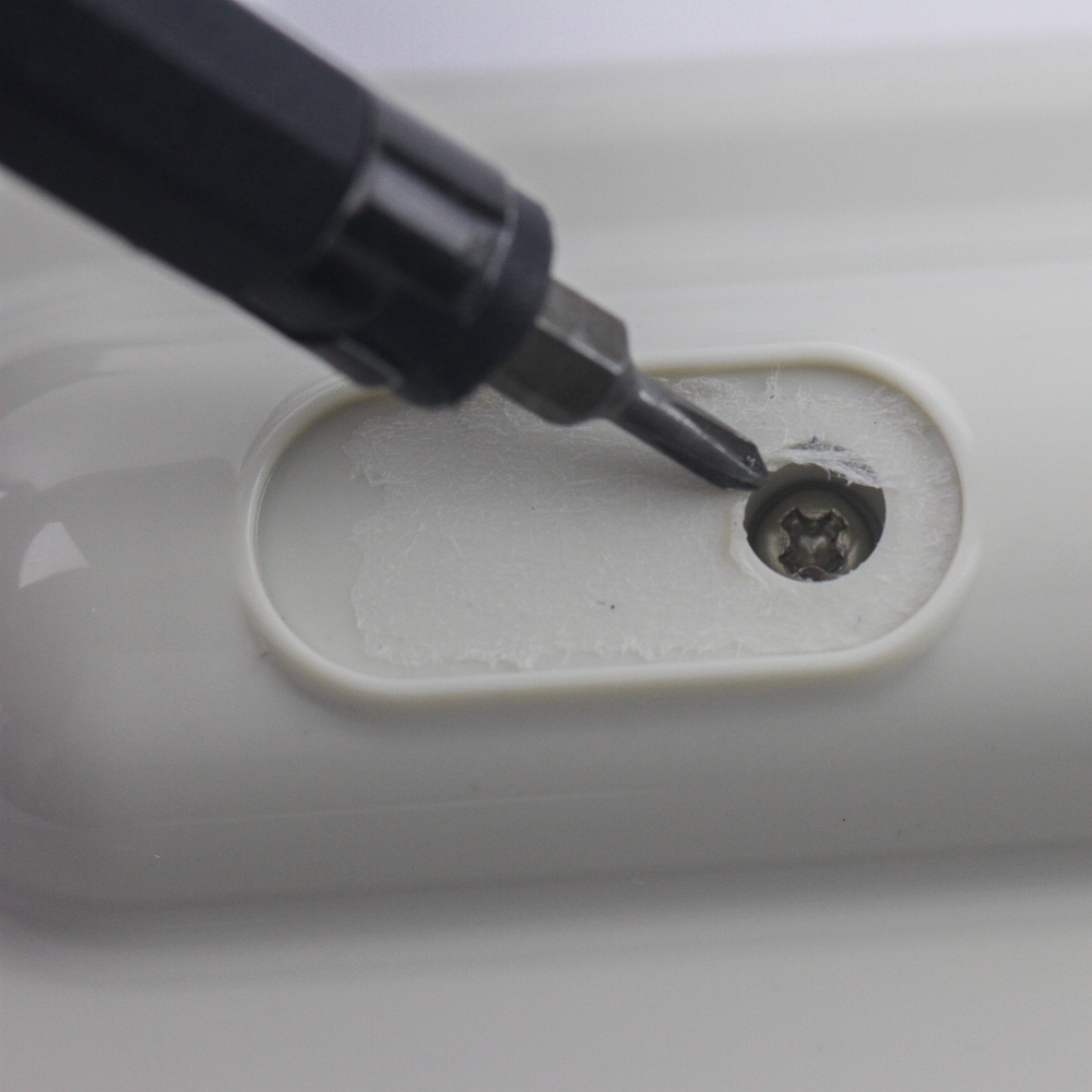
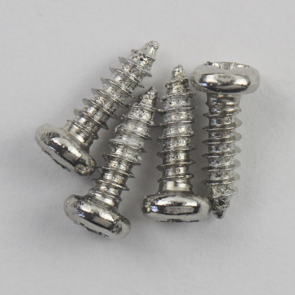

There is very little reason to disassemble the Epomaker B21, except for science, of course. So here we are then, and the process begins by noting four hidden Phillips-head screws under the rubber pads on the back. With all four removed, you will need to use a thin, flat object to pry apart the interlocking plastic tabs holding the plastic case pieces together. Pull out the two knob covers, too, since they prevent the top case panel from coming off completely. This also means there is scope for differently colored knobs, but I don't believe Epomaker will have multiple colors available for this keyboard.
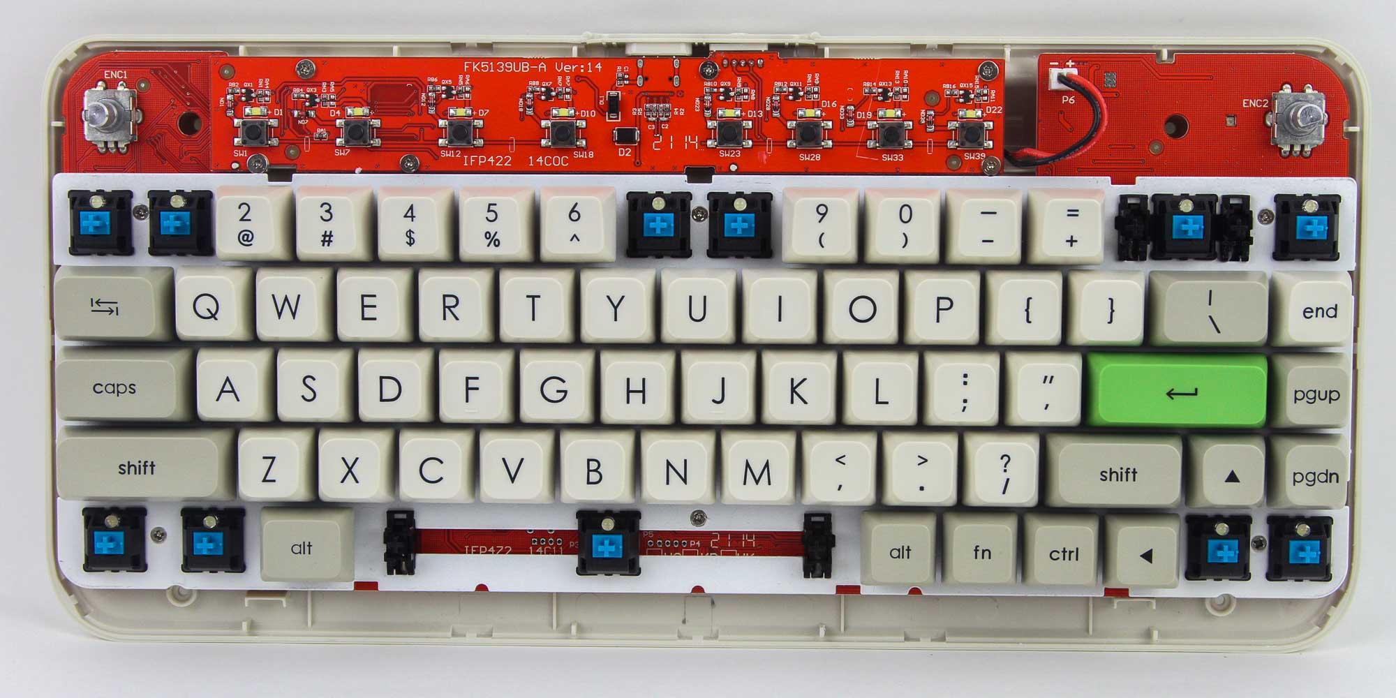
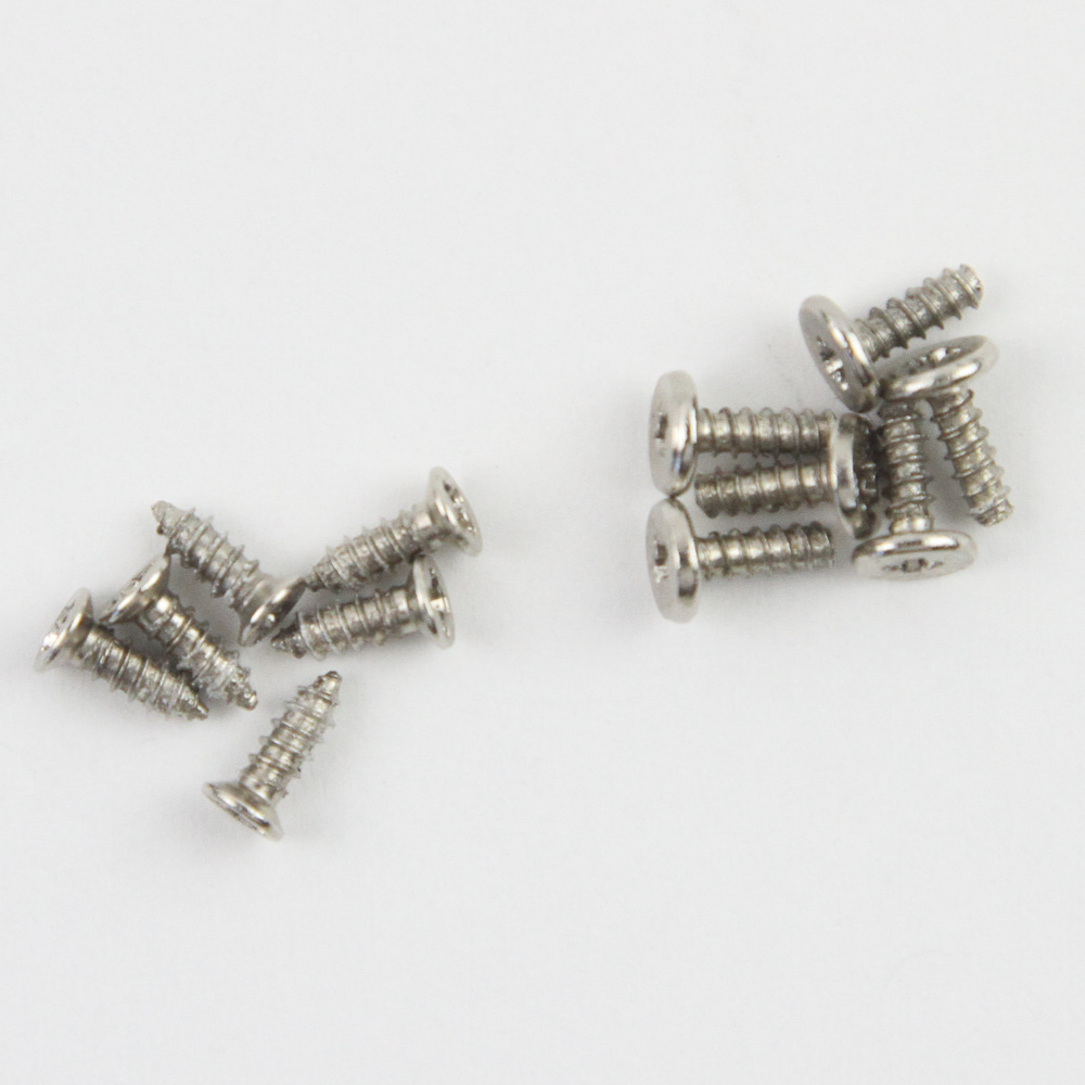
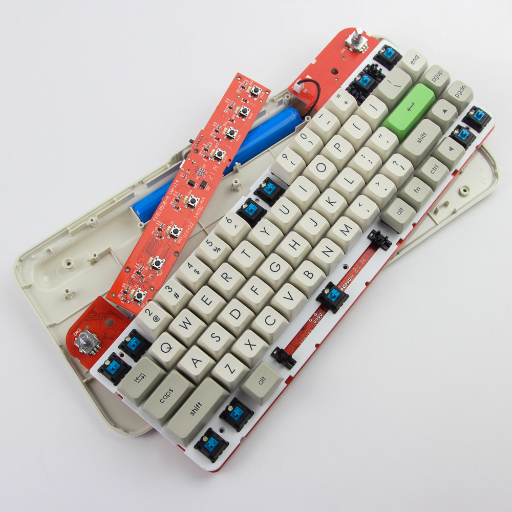
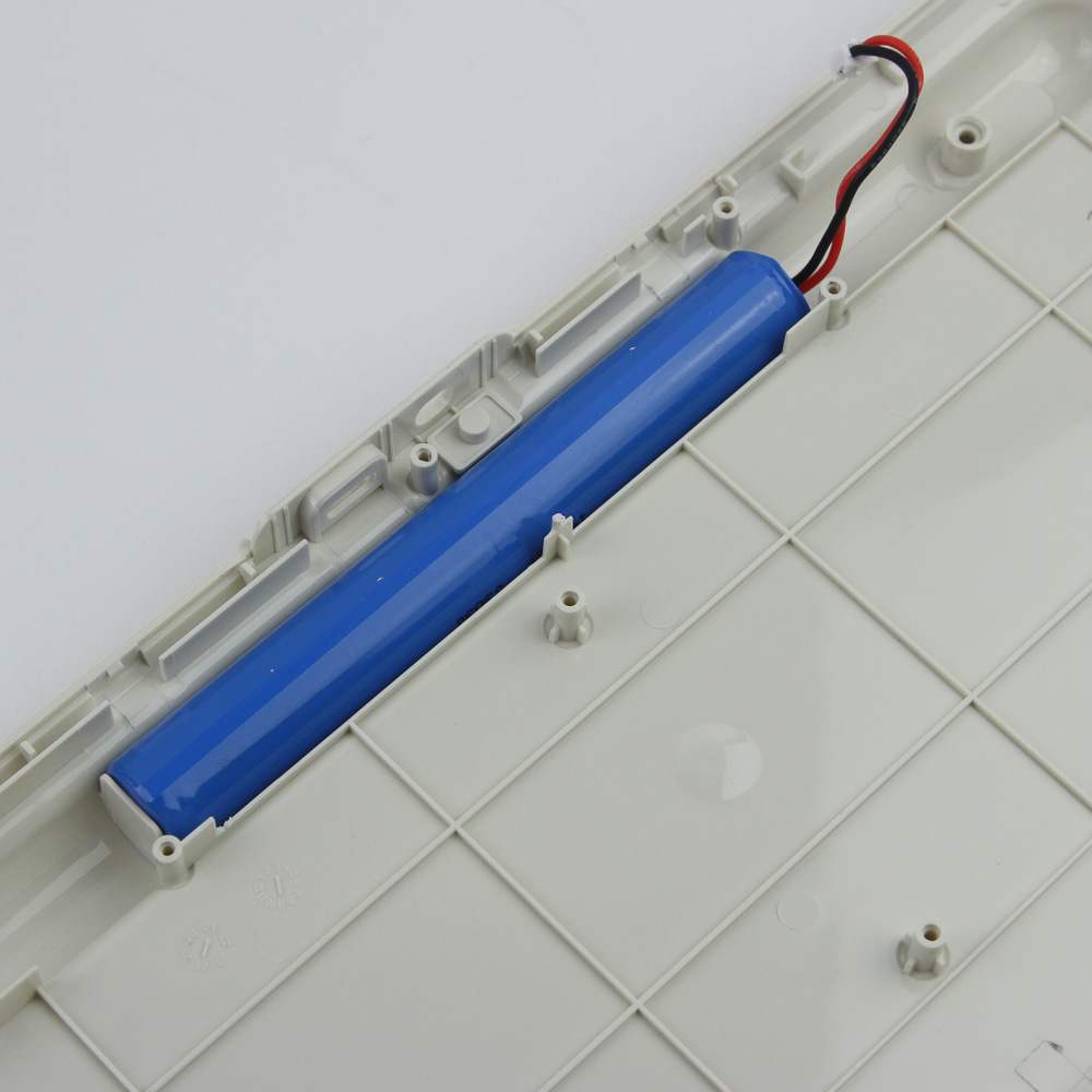
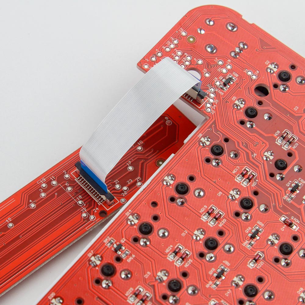
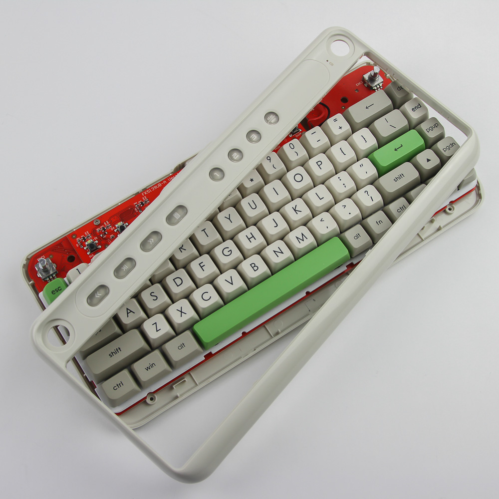
As with the bottom panel, the top plastic panel is made out of ABS plastic. It also houses the seven buttons up top in addition to the knobs, and these buttons are associated with tactile buttons on a daughter PCB, as well as more LEDs to help actually backlight these buttons. Further disassembly requires the removal of six Phillips head screws holding the daughter PCB in place on the bottom plastic panel, as well as an additional six Phillips head screws underneath specific keycaps as seen above. These screws secure the primary PCB, and you can now lift off both PCBs together. Do so carefully since only a ribbon cable supports the daughter PCB. There is also a power cable to be dislodged from the primary PCB, which in turn is of the battery in the bottom panel that powers the wireless operation of the Epomaker B21. The battery appears to consist of just two combined AA batteries, which provide a relatively massive 4000 mAh in total. Removing the daughter PCB requires carefully removing the ribbon cable from the connector on the primary PCB.
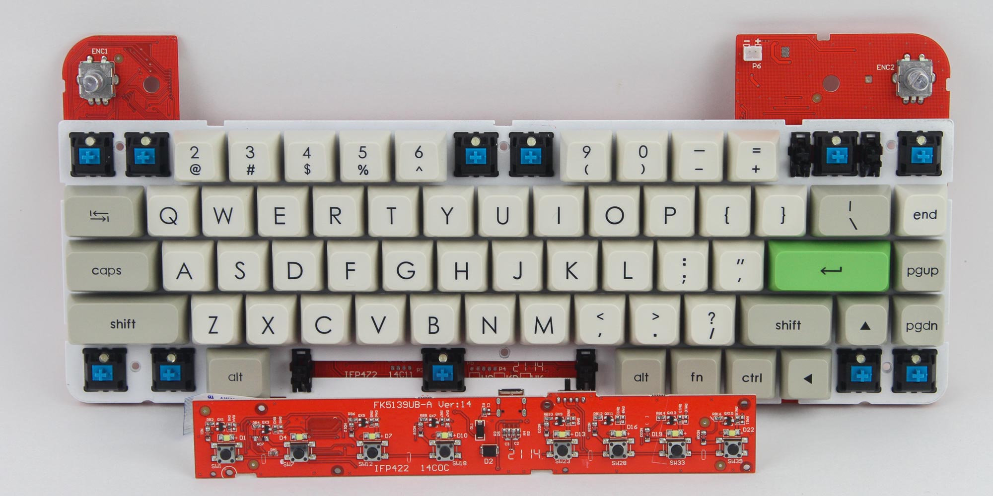
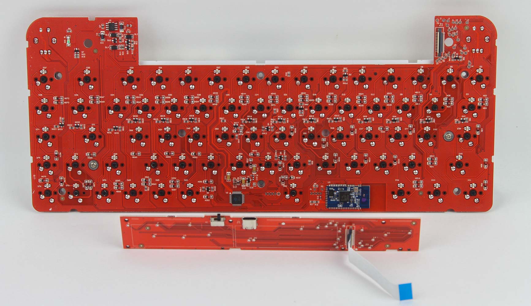
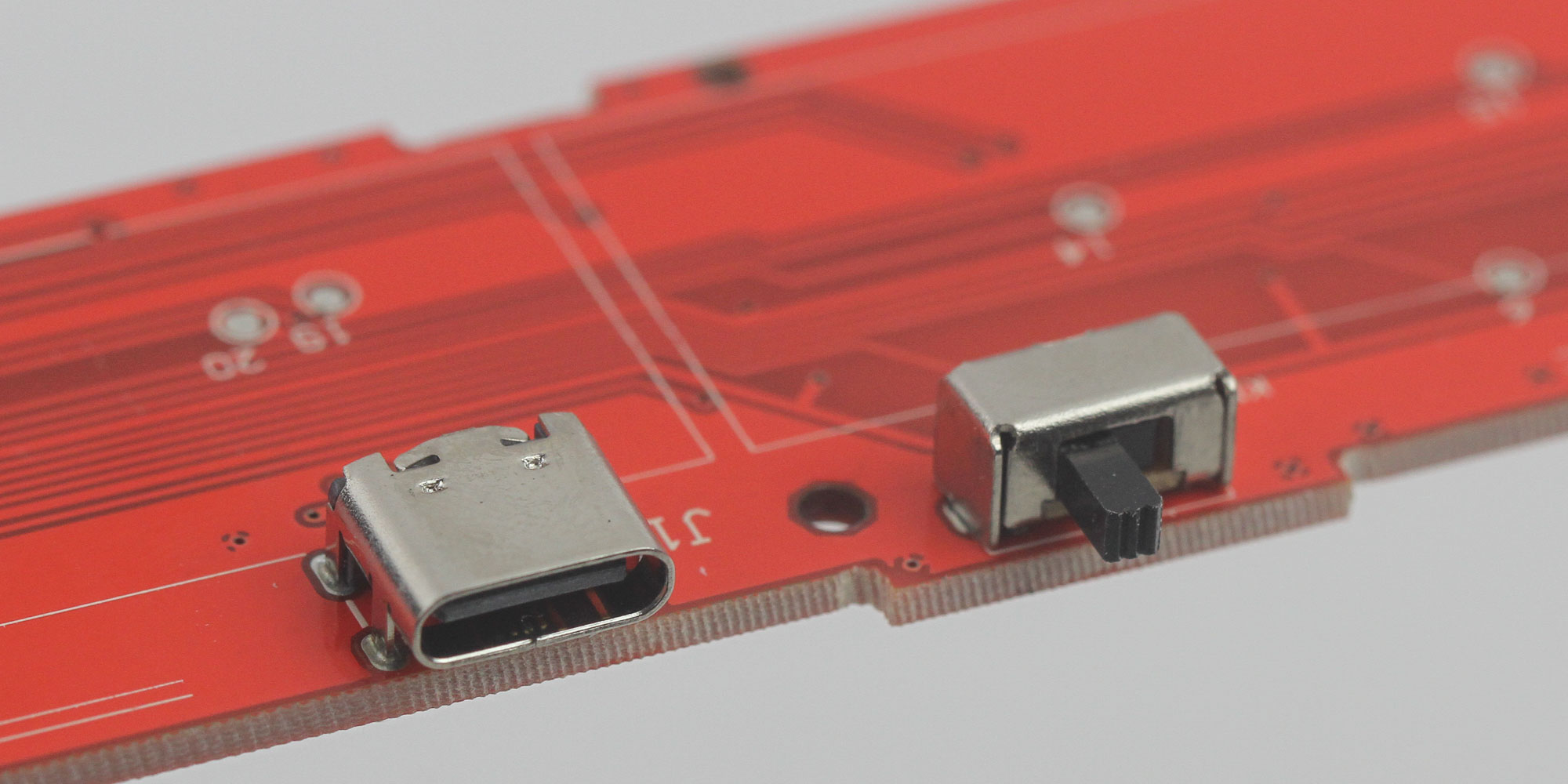
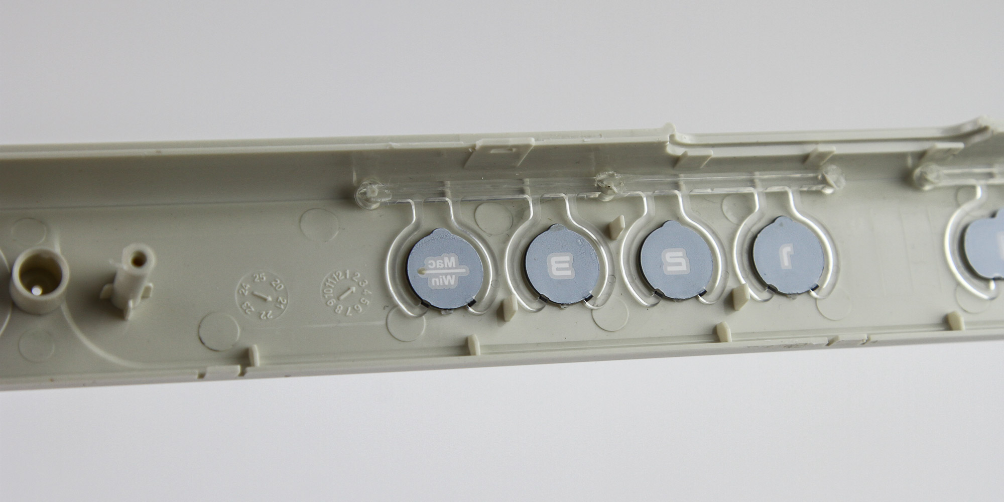
This is not only a unique-looking keyboard on the outside, but also a unique PCB design on the inside. Both PCBs are red, with the primary PCB having a large cutout to accommodate the daughter PCB in the space and slightly above it. There are seven tiny tactile buttons on the smaller PCB on one side, with the other side hosting the toggle switch for the connectivity modes as well as the USB Type-C port. The plastic toggle housing is now loose on the bottom plastic panel, and you need to make sure the position aligns with the physical switch when reversing these steps to re-assemble the keyboard.
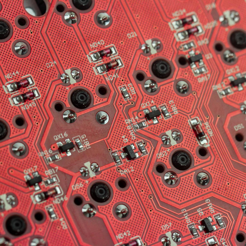
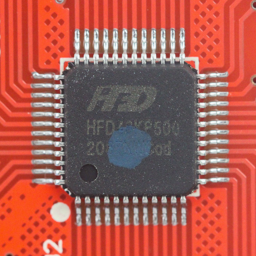
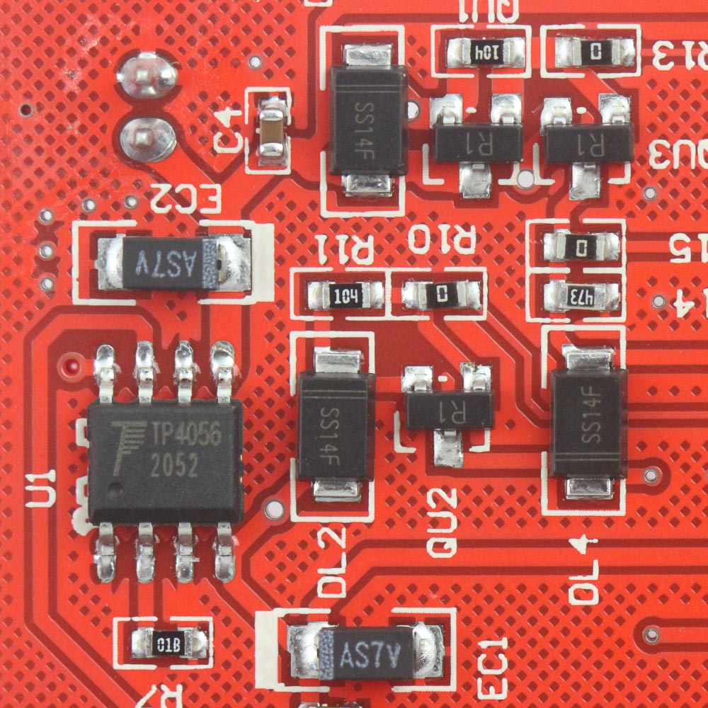
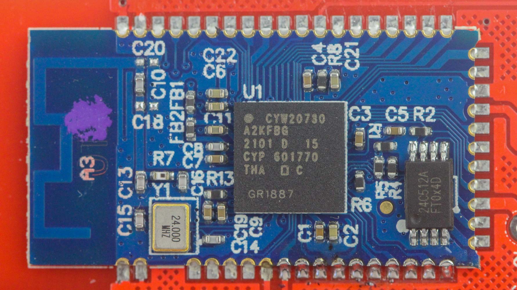
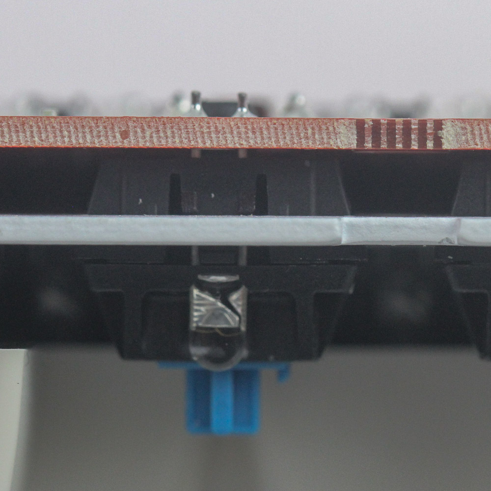
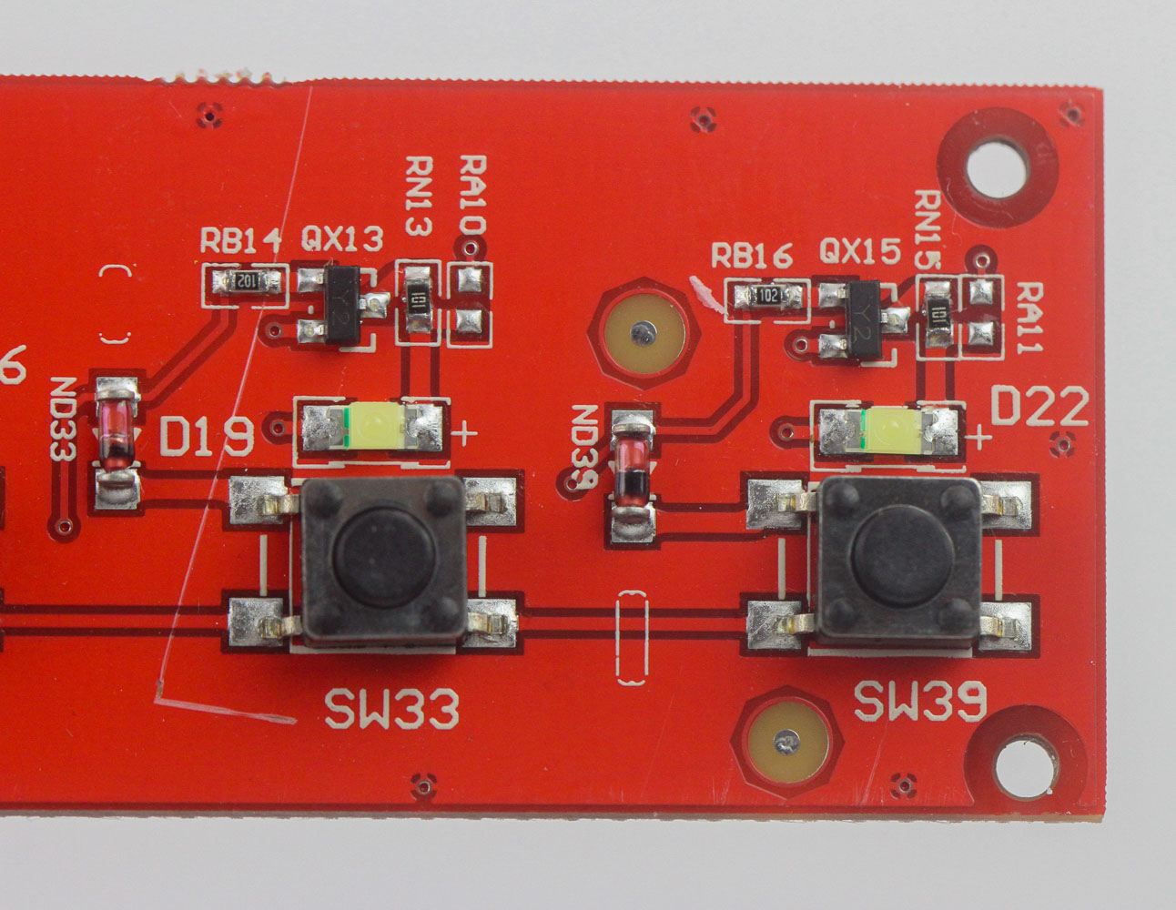
Solder quality is very good for all the components, and we see that there are no hot-swap switch sockets, with the Cherry MX switches soldered through a steel plate and onto the PCB itself. The steel plate is white, which should help reflect the white lighting here, although the primary purpose is to add structural integrity to the keyboard. Powering the wired connectivity of the Epomaker B21 is an HFD48KP500 USB microcontroller for which there is little information available online aside from it having been used in similar keyboards in the past. Wireless connectivity is powered by a Cypress CYW20730 Bluetooth 5.1 processor and integrated 2.4 GHz transceiver. All the components, including the switches, LEDs, and capacitors, are soldered to a multi-layered PCB.
Before we move on, be advised that disassembly may void the warranty and that TechPowerUp is not liable for any damages incurred if you decide to go ahead and do so anyway.
Feb 6th, 2025 14:31 EST
change timezone
Latest GPU Drivers
New Forum Posts
- TOXIC AMD Radeon™ RX 6900 XT (38)
- Last game you purchased? (657)
- RX 580 Aorus with wrong vbios (7)
- S20+ boot looping (6)
- Razer Blade 15 3080Ti Vbios Flash Help (5)
- Post your Monster Hunter Wilds benchmark scores (26)
- Copying big amount data from HDD (1)
- AMD on a Gsync Monitor? (13)
- Optane / 3DXPoint - legacy and fate (2)
- What are you playing? (22788)
Popular Reviews
- Spider-Man 2 Performance Benchmark Review - 35 GPUs Tested
- Kingdom Come Deliverance II Performance Benchmark Review - 35 GPUs Tested
- Corsair Frame 4000D Review
- NVIDIA GeForce RTX 5080 Founders Edition Review
- Formovie Cinema Edge 4K UST Laser Projector Review
- Gigabyte GeForce RTX 5080 Gaming OC Review
- MSI GeForce RTX 5080 Vanguard SOC Review
- AMD Ryzen 7 9800X3D Review - The Best Gaming Processor
- ASUS GeForce RTX 5080 Astral OC Review
- Dan Clark Audio NOIRE X Closed-Back Headphones Review
Controversial News Posts
- NVIDIA 2025 International CES Keynote: Liveblog (470)
- AMD Debuts Radeon RX 9070 XT and RX 9070 Powered by RDNA 4, and FSR 4 (349)
- AMD Radeon 9070 XT Rumored to Outpace RTX 5070 Ti by Almost 15% (285)
- AMD is Taking Time with Radeon RX 9000 to Optimize Software and FSR 4 (256)
- AMD Denies Radeon RX 9070 XT $899 USD Starting Price Point Rumors (239)
- Edward Snowden Lashes Out at NVIDIA Over GeForce RTX 50 Pricing And Value (235)
- AMD Radeon RX 9070 XT & RX 9070 Custom Models In Stock at European Stores (226)
- New Leak Reveals NVIDIA RTX 5080 Is Slower Than RTX 4090 (215)