 6
6
Fractal Design NEWTON R3 1000 W Review
Voltage Regulation, Hold-up Time & Inrush Current »A Look Inside & Component Analysis
Before reading this page, we strongly suggest a look at this article, which will help you understand the internal components of a PSU better. Our main tool for the disassembly of the PSU is a Thermaltronics TMT-9000S soldering and rework station. It is of extremely high quality and is equipped with the matching soldering gun. With such equipment in hand, breaking apart every PSU is like a walk in the park!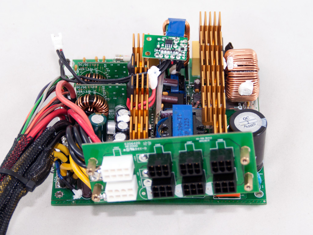
The OEM of the PSU is ATNG, a manufacturer we encountered last in the In Win Glacier 900 W review. The platform is modern, and the primary side has an LLC converter that boosts efficiency, while the secondary side uses synchronous rectification and two DC-DC converters that generate the minor rails.
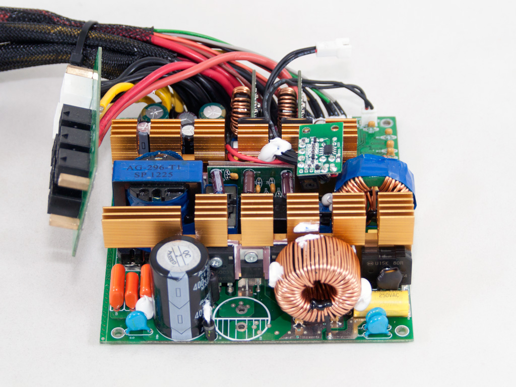
A small PCB behind the AC receptacle holds many of the transient filter's components - namely, three X caps, four Y caps, and a CM choke. The transient filter continues on the main PCB with two X caps and a CM choke. Behind the bride are two Y caps and an MOV. The latter is usually placed before the bridge rectifier for protection against surges.
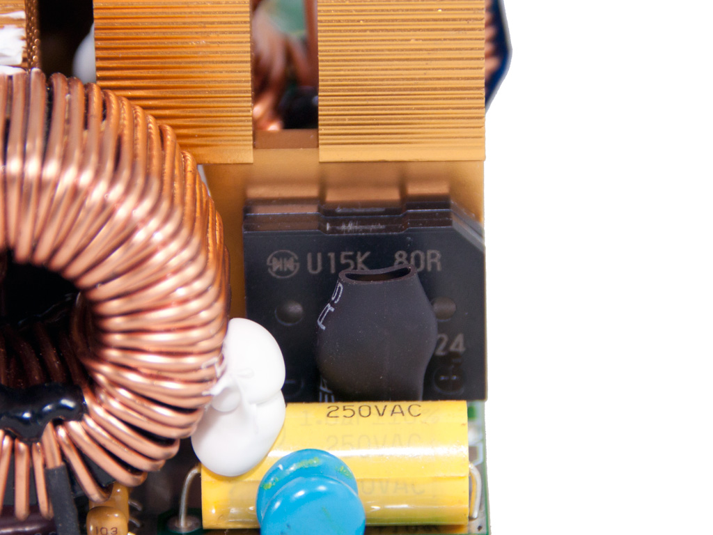
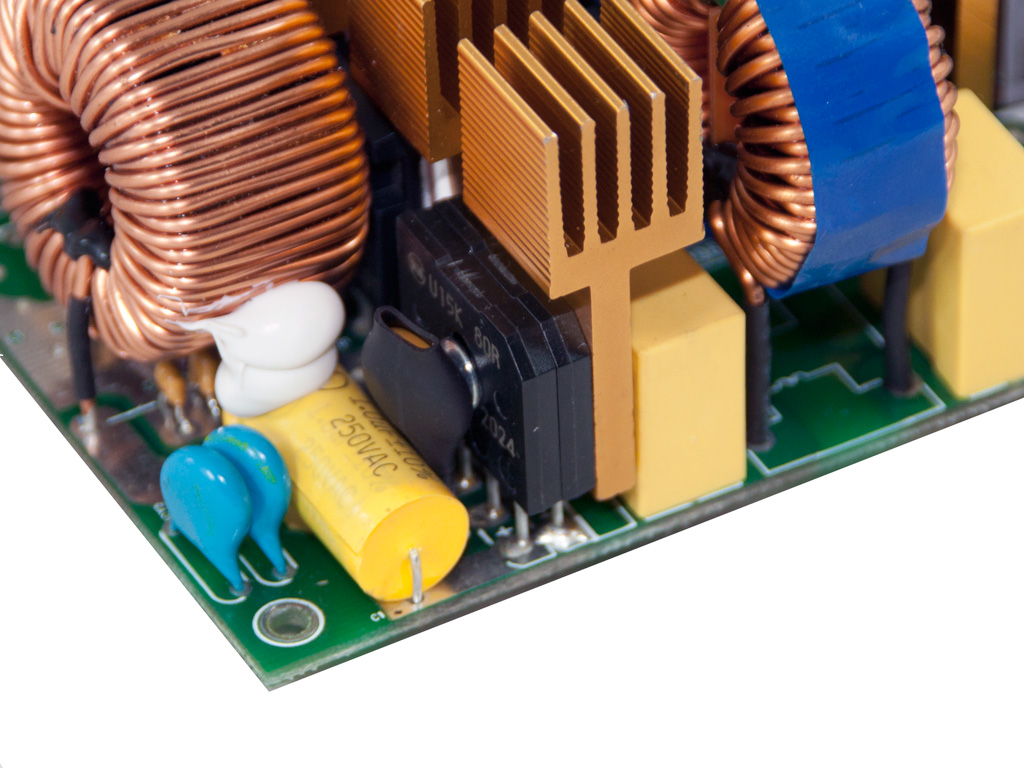
The two parallel bridge rectifiers are bolted together on the APFC/primary heatsink. Their model number is U15K80R, and we couldn't find any information for them on the web.
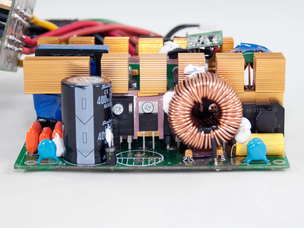
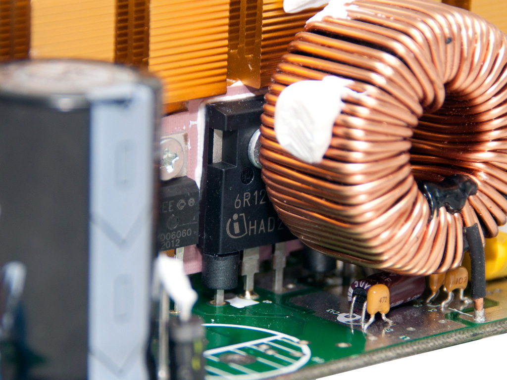
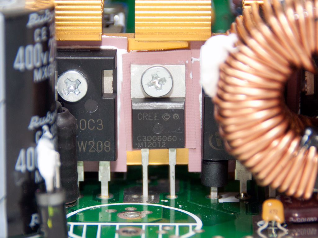
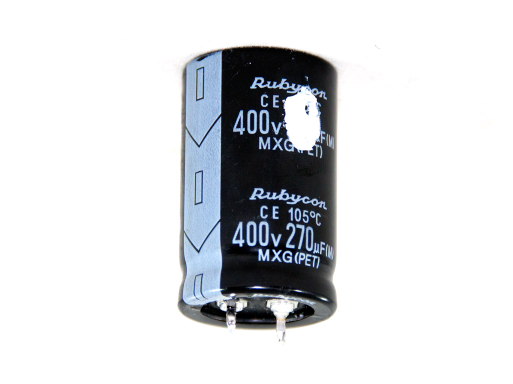
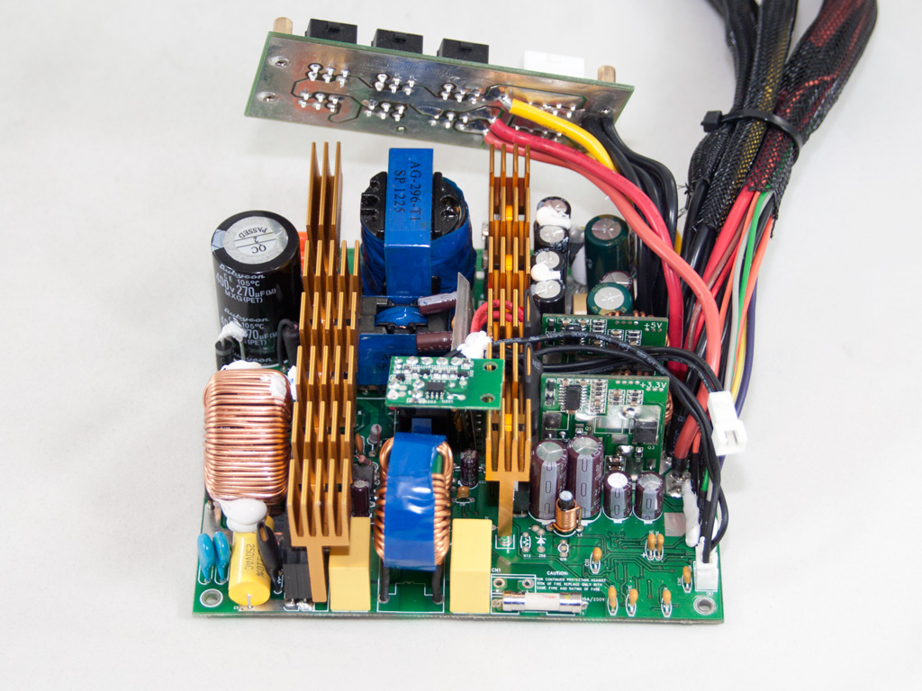
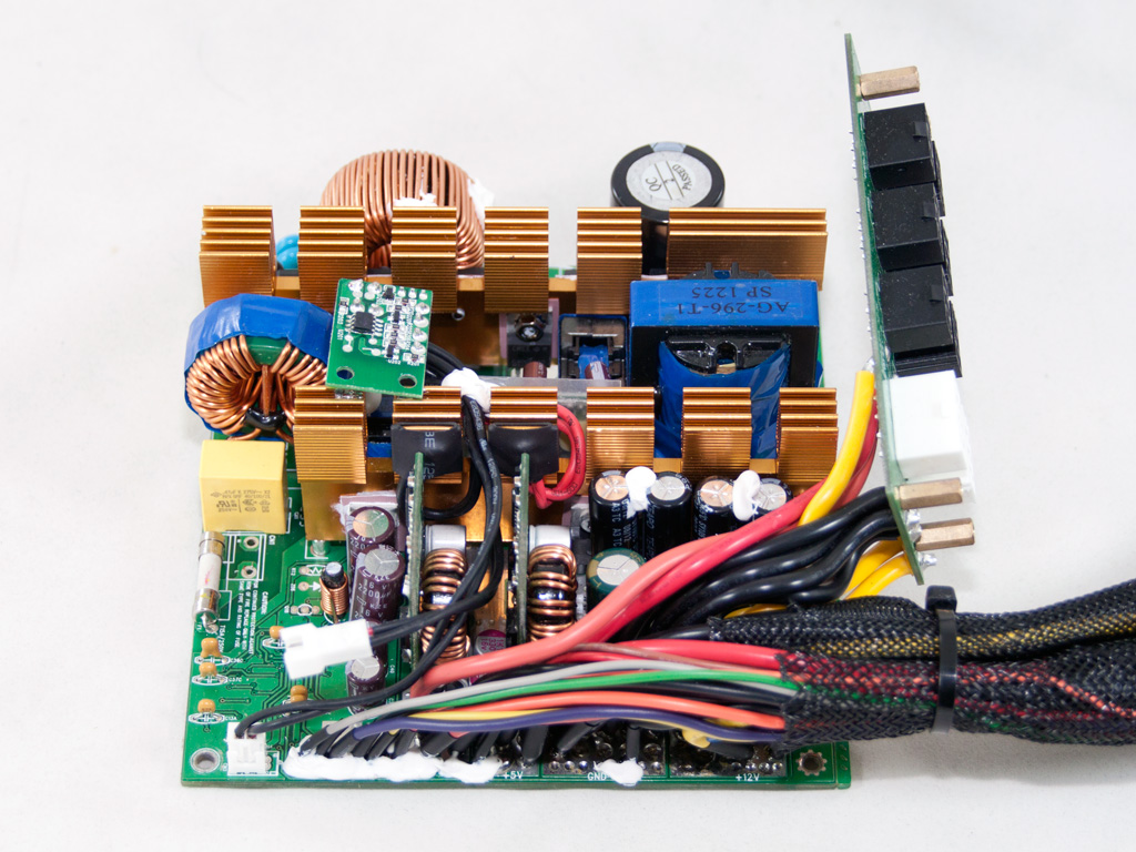
In the APFC, two Infineon IPW60R125CP are used along with two CREE C3D10060 boost diodes. The hold-up caps are two parallel Rubycons (270 µF each or 540 µF combined, 400V, 105°C). Their combined capacity is pretty low for the 1 kW max power that this unit can deliver. The PFC controller is a 2PCS01 IC that has been installed on the solder side of the main PCB.
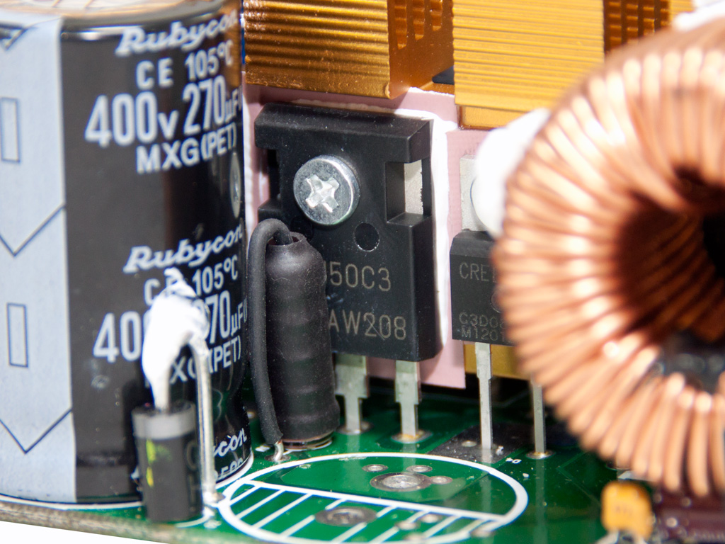
The main switchers are two SPW32N50C3 fets. They are assisted by an LLC converter.
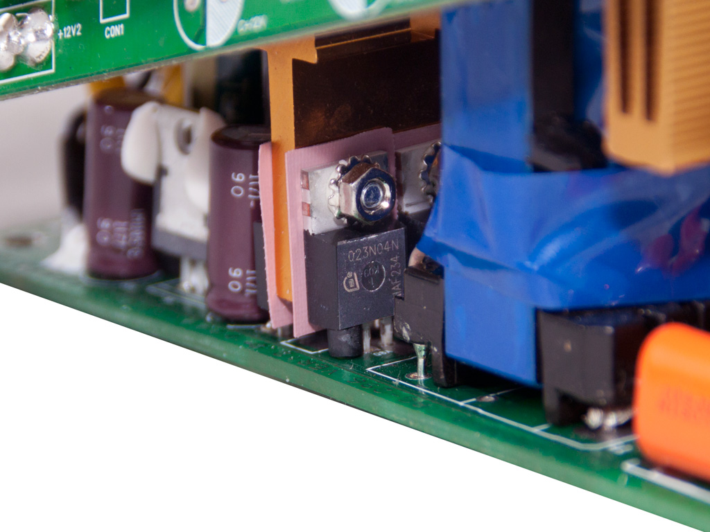
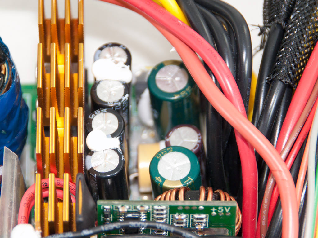
The secondary side utilizes synchronous rectification for the generation of the +12V rail, and eight IPP023N04N fets are used. Ripple filtering on this rail is taken care of by a bunch of Teapo and Nippon Chemi-Con electrolytic caps - all of them rated at 105°C - and two polymer Enesol caps between the DC-DC converters.
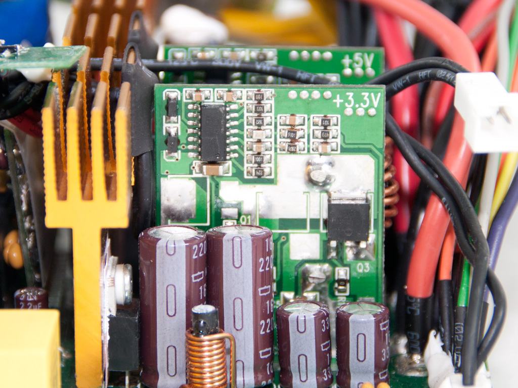
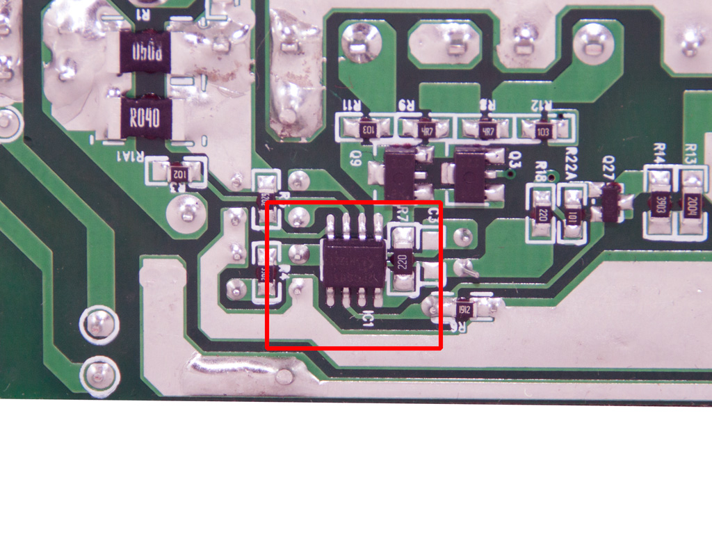
The minor rails are generated by two DC-DC converters. We find a CAT7523 PWM controller along with two fets on each one.
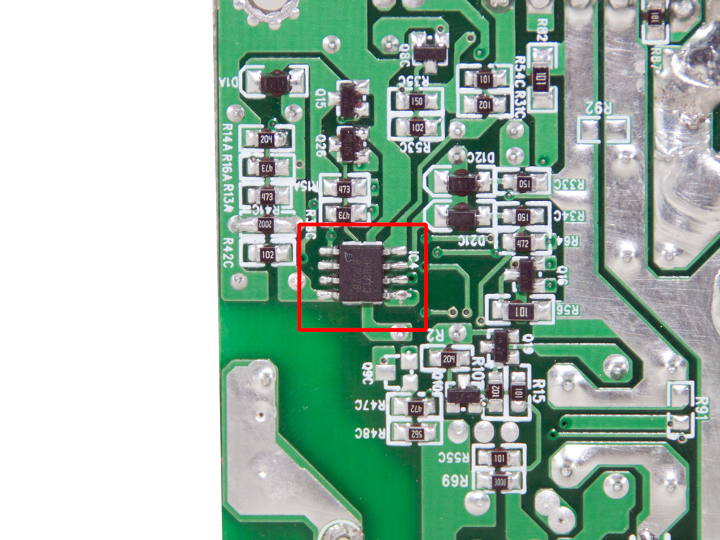
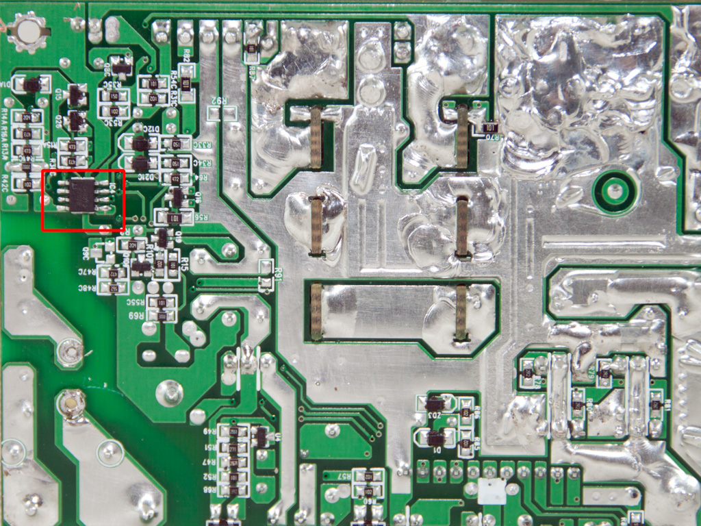
The supervisor IC is located on the solder side of the main PCB, and its model number is GR8313. It only provides two protections (OVP and UVP). We didn't expect to see such a low-end supervisor IC in a high-end PSU.
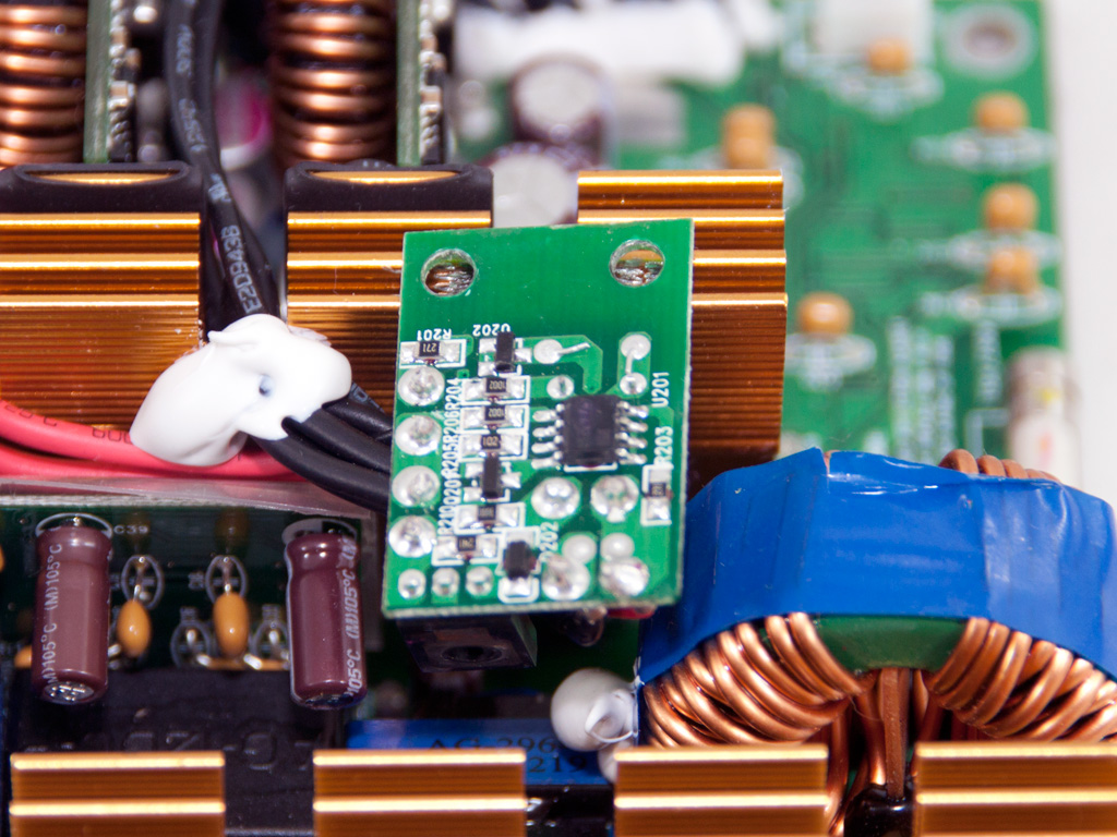
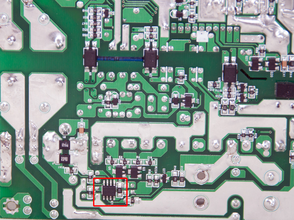
The circuit that controls the fan's speed is located on a small PCB bolted onto the secondary heatsink. The IC that can be seen on the photo above is an LM393 voltage comparator. The fan speed control circuit also receives temperature information from two thermistors installed on the secondary heatsink.
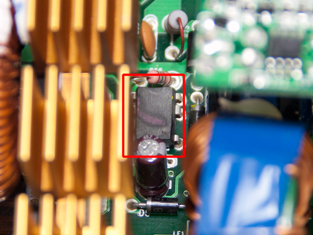
The markings on the standby PWM controller have been erased fully, but we think that it is a TNY277 IC.
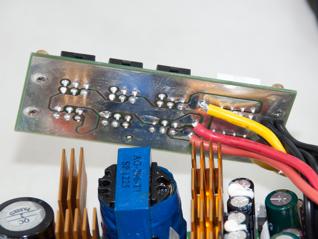
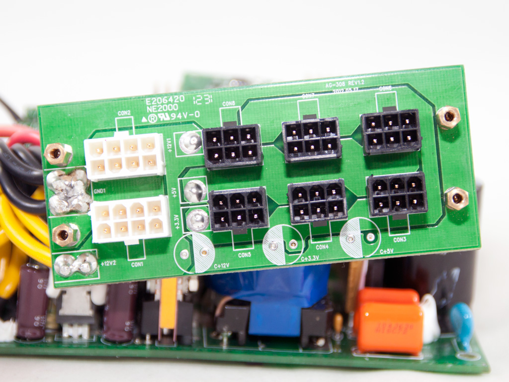
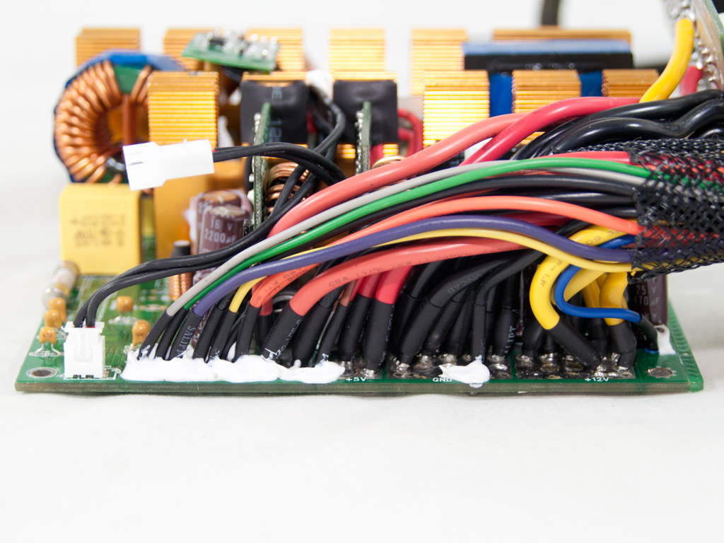
Several thick wires transfer the main rails and provide earth to the modular PCB. No caps for further ripple suppression have been installed to the front of the same PCB, although there is enough room for three of them.
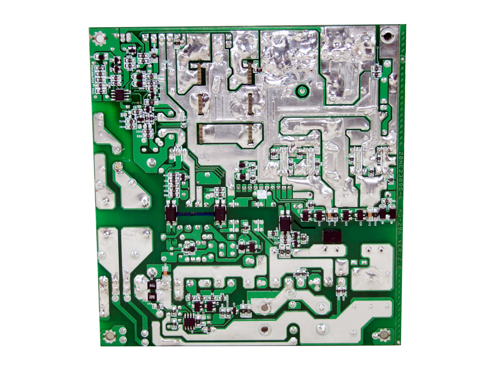
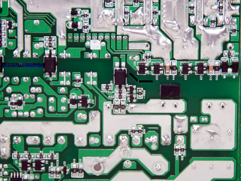
Soldering quality on the main PCB is good overall, although there are several spots with soldering joints that don't look so good.
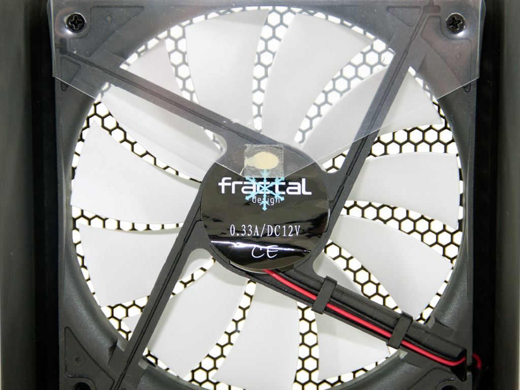
The cooling fan carries Fractal's logo, but we are pretty sure that it is made by another company, most likely Globe Fan. We also suspect that it is the same fan that the In Win Glacier 900 W uses, so its model number is RL4Z B1352512H (12 V, 0.33 A, 106.86 CFM, 1500 RPM, 29.2 dBA). Finally, a triangular plastic baffle has been attached to the fan to direct airflow towards the front of the PSU.
Feb 23rd, 2025 20:06 EST
change timezone
Latest GPU Drivers
New Forum Posts
- Will undervolting a 4090 keep the connector from melting? A discussion about electrical theory. (36)
- What's your latest tech purchase? (23202)
- RDNA4 Prediction Time Part Deux!!! (32)
- Keep a 4080s or take a 5070ti? (46)
- Warning about DOCP (17)
- 16TB (13)
- revisiting hpet bcdedit tweaks: what are your timer bench results and settings? (94)
- Testing max ram overclock pn Ryzen 1700 (72)
- Need help dumping/imaging Lenovo laptop BIOS (3)
- Dune: Awakening benchmark - post your results (17)
Popular Reviews
- ASUS GeForce RTX 5070 Ti TUF OC Review
- MSI GeForce RTX 5070 Ti Ventus 3X OC Review
- darkFlash DY470 Review
- MSI GeForce RTX 5070 Ti Vanguard SOC Review
- MSI GeForce RTX 5070 Ti Gaming Trio OC+ Review
- Galax GeForce RTX 5070 Ti 1-Click OC White Review
- Palit GeForce RTX 5070 Ti GameRock OC Review
- Fantech Aria II Pro Review
- Gigabyte GeForce RTX 5090 Gaming OC Review
- AMD Ryzen 7 9800X3D Review - The Best Gaming Processor
Controversial News Posts
- NVIDIA GeForce RTX 5090 Spotted with Missing ROPs, NVIDIA Confirms the Issue, Multiple Vendors Affected, RTX 5070 Ti, Too (448)
- AMD Radeon 9070 XT Rumored to Outpace RTX 5070 Ti by Almost 15% (304)
- AMD Plans Aggressive Price Competition with Radeon RX 9000 Series (271)
- AMD Radeon RX 9070 and 9070 XT Listed On Amazon - One Buyer Snags a Unit (247)
- Edward Snowden Lashes Out at NVIDIA Over GeForce RTX 50 Pricing And Value (241)
- AMD Denies Radeon RX 9070 XT $899 USD Starting Price Point Rumors (239)
- NVIDIA Investigates GeForce RTX 50 Series "Blackwell" Black Screen and BSOD Issues (225)
- New Leak Reveals NVIDIA RTX 5080 Is Slower Than RTX 4090 (215)