 69
69
Gigabyte B650E AORUS Master Review
VRM Overview »Board Layout


Gigabyte has continued to use a more neutral tone, first seen with the other AORUS motherboards over this last generation. Anybody who's seen a Gigabyte motherboard in the last 10 years will be familiar with the bright orange accents that defined Gigabyte branding. Lately the trend for many companies has been to tone down the "gamer vibe" to appeal to a wider consumer base. It certainly isn't a bad thing either from a sales perspective. The entire back is covered by a backplate designed to relieve stress in a uniform manner, and provide additional cooling with thermal pads sandwiched in between. This isn't just for show and serves a purpose outside of being a hazard guard.
Being that this motherboard is using the B650E chipset, there is more room available in the PCH area. This means unlike many of the X670E motherboards, the standard ATX form factor is more common, which is great for case compatibility. Along with a new chipset, the CPU socket has physically changed. Together with firmware and design changes, this also physically prevents previously released Ryzen CPUs (Zen1, Zen2, Zen3) from being installed, which will not be compatible moving forward, for a clean sheet generational leap.

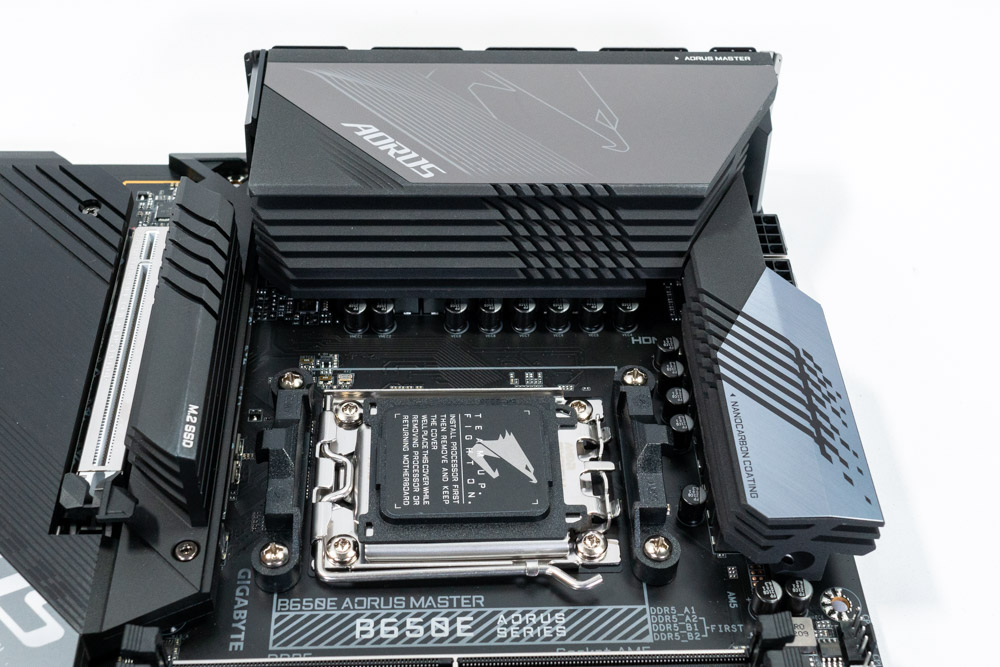
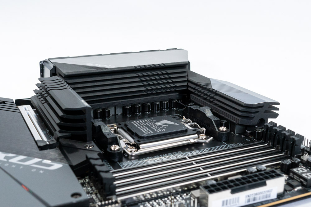
AMD's changes to the socket also comes with some compatibility challenges. Many brands selling CPU coolers have already announced forwards compatibility. However, some will need an adapter, as the backplate that was previously removable for the AM4 (PGA) socket is now an integral part of this new AM5 (LGA) socket. The Gigabyte B650E AORUS Master's surrounding heatsinks encroach on the available socket space somewhat. On each side are items that are considered tall enough to be of some concern. Below the socket is the M2 heatsink. To the left and top is the VRM heatsink, and to the right is the memory. Most All-In-One (AIO) coolers should have no issue with the space available, but air coolers may conflict, depending on orientation.
AMD recommends 240-280 mm AIO (or better) for the Ryzen R9 7950X/7900X to keep the turbo frequency on target. Thermal observations from using the AMD Ryzen 7950X during this review places the CPU at 95°C, which is perfectly normal. The AIO solution isn't a requirement if heavy multi-threaded application performance is a priority, though it will provide the highest boost clocks overall. Undervolting, and using PBO is also an option as well to circumvent CPU cooler thermal limitations. AMD ECO Mode also is a option as it sets the target wattage to 90 and still performs quite well, matching the performance of an Ryzen 5950X in Cinebench R23. For more information regarding Ryzen 7000 cooling requirements, TechPowerUp has a great article covering this specific topic. Click THIS for Article LINK.
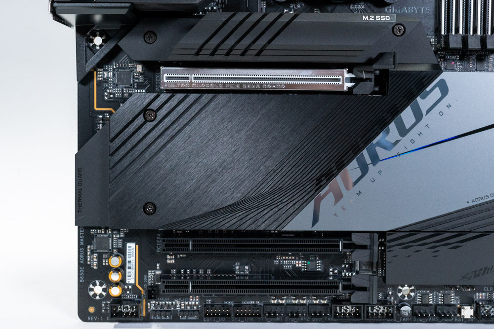
The Gigabyte B650E AORUS Master offers three PCI Express x16 slots, with the first being reinforced for extra stress support. PCIe slot one is PCIe Gen5 certified with a total of x16 lanes coming from the CPU. This connection drops to x8 when either of M.2 sockets (M2B_CPU and M2C_CPU) are populated, due to sharing the available PCIe lanes. PCIe slot two and three are a bit complicated as well. Both are physically x16, but internally wired for Gen4 x4. Slot two will support x4, while slot three is only setup as PCIe x2 as stated by the manual.
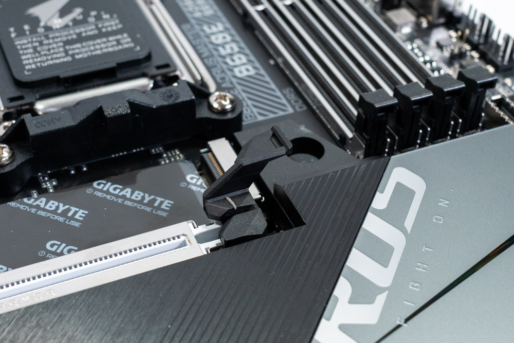
In the last few generations of motherboards, because M.2 sockets have become more popular, so has the space around PCIe slots become more restricted. It's not uncommon to have to remove a M.2 heatsink to be able to release video cards because the PCIe latch is hard to reach with just fingers. Sometimes you can use a flat head screwdriver instead, if you are feeling brave. Luckily Gigabyte has devised a plan to solve this. On some of the motherboards like for example, the Gigabyte X670E Master, there's a button that releases the graphics card with minimal effort. Here, Gigabyte just puts a different ended latch so you don't have to remove anything to get the video card out.

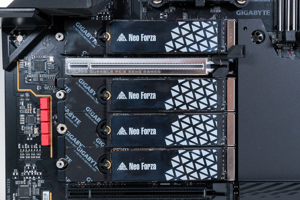
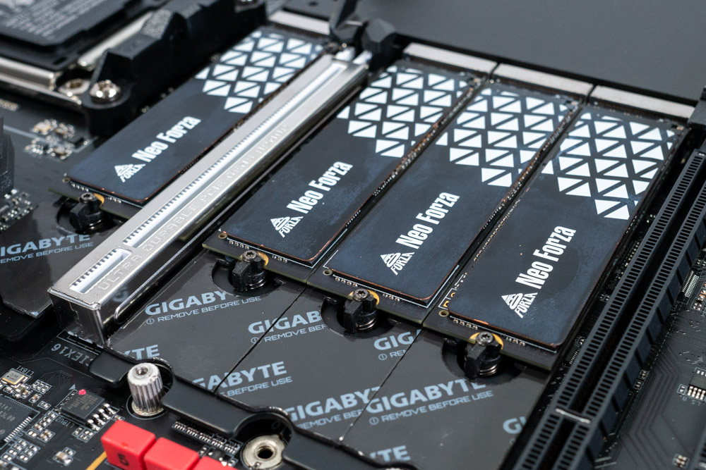
The AMD Ryzen 7000 series of CPUs provides 24 PCIe Gen5 lanes which is split up as 16+4+4. With x16 designated for PCIe slot(s), x4 dedicated to M.2 Gen5 and x4 use for general purposes. While it is expected for a B650 or X670 to have at least one M.2 Gen5 socket, Gigabyte has taken this to another level. All four M.2 sockets on this B650E AORUS Master motherboard are Gen5 x4. This is accomplished by using the 4+4 lanes, as well as taking half of the x16 PCIe Gen5 slot. When M.2 socket three and four are populated, the first PCIe slot will be limited to Gen5 x8. It's important to bear in mind that if all four M.2 sockets are populated, the PCIe slot is limited to x8, regardless of the generation of the GPU plugged in, e.g. a Gen4 RTX 3080 would also be limited to Gen4 x8. To get a feel for the performance impact, see the techpowerup PCIe scaling article.
On the B650E AORUS Master, Gigabyte has also removed the need for M.2 screws. In their place are quick release clips, which are wonderful to have when considering lost M.2 screws.

In the top right corner are physical power and reset buttons. These buttons are helpful if you just want to power on the motherboard before you have everything connected up, or if it's on a test bench.
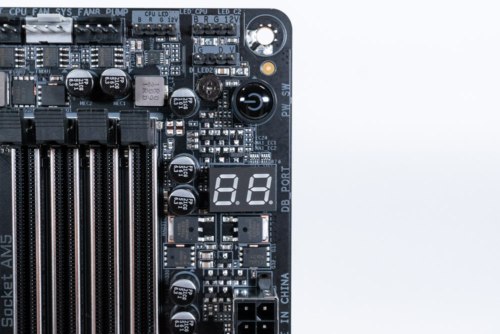
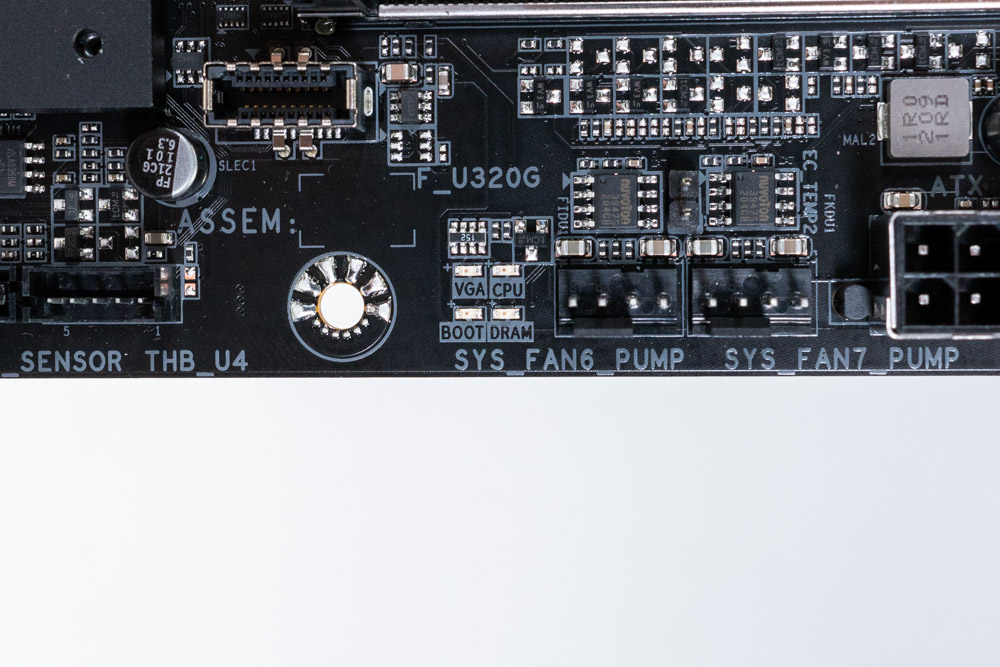
The Gigabyte B650E AORUS Master includes a post code debugger and startup LEDS for easier troubleshooting. Considering that the AM5 socket is new to everyone, it is always good to get a readout of what stage the boot process is on, or what it may be stuck on. First boot after clearing the CMOS or installing new memory will take anywhere from two to six minutes, depending on the configuration.
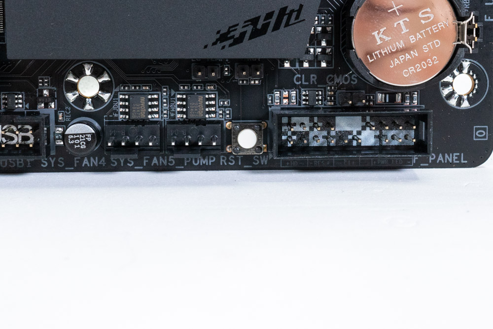
In the bottom right corner is a multi-key button next to the Front Panel Header. This is labeled RST_SW, which stands for Reset Switch. While not an actual switch, this button can be configured in the BIOS to turn off the LEDs, Direct to BIOS or boot to Safe Mode. By default it is a Reset button, as marked on the motherboard.
While we are looking at this picture, above the Front Panel Header is a 2-pin jumper pad used for clearing the CMOS. This is Just in case the button on the Rear IO stops working. The other option to Clear the CMOS is to remove the battery as well.
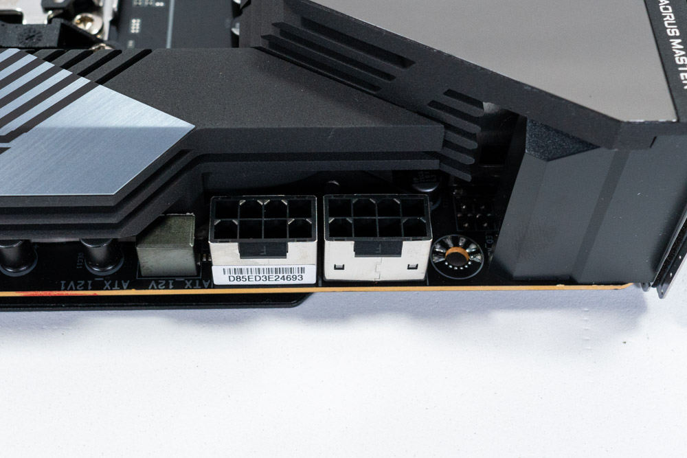
The Gigabyte B650E AORUS Master uses a two 8-Pin EPS connector for higher power management.
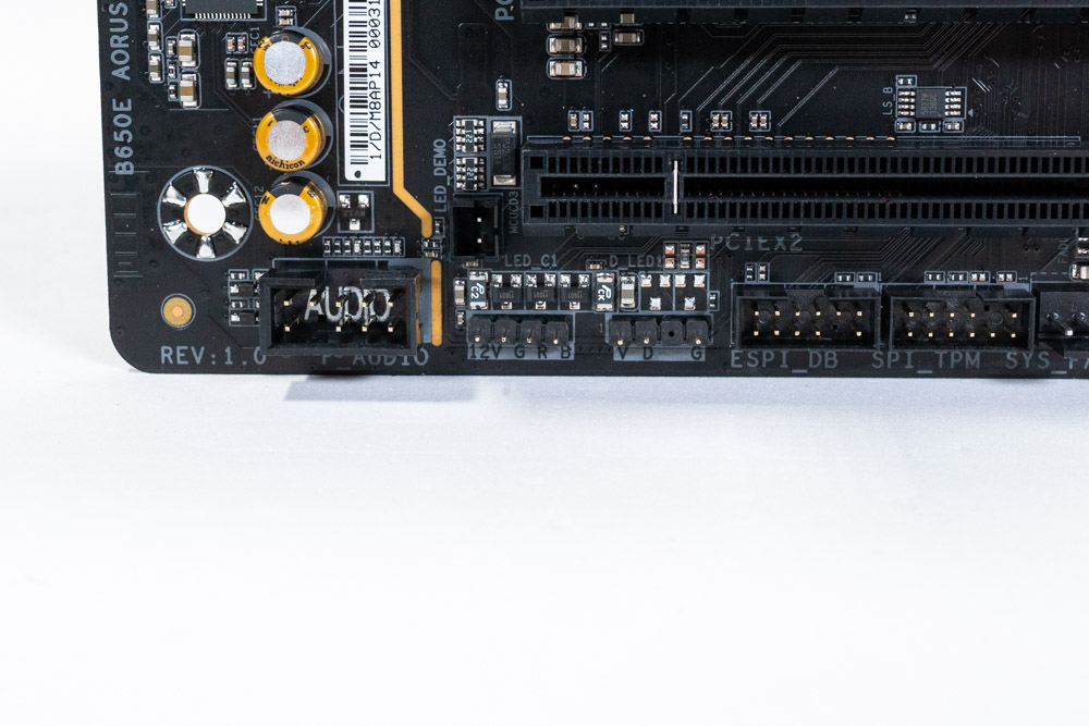
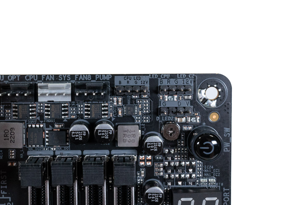
In the top right corner are three RGB headers, along with two in the bottom left corner. The three across the top are interesting, as the one on the left says CPU LED, which supplies 12 V (4-pins). Next to that is another 12 V (4-pins), while directly below is the ARGB 5 V (3-pins) header. The CPU RGB header doesn't have to be strictly for the CPU cooler, but it will be labeled this in the software. On the bottom of the motherboard are two more RGB headers. The one of the right is 5 V, with 12 V on the left.
| Connector | RGB LED Header | ARGB LED Header |
|---|---|---|
| Maximum Current | 12V / 2 A | 5V / 5 A |
| Maximum Power | 24W | 25W |
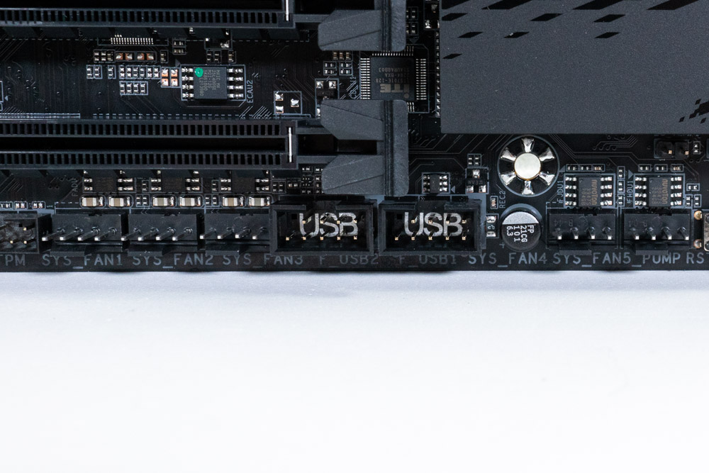
One of the major differences you'll see between the X670 and B650 chipset is the amount of internal USB header and external high-speed connections. This is because the chipset itself has less PCIe lanes available to be allocated towards SATA ports, USB and PCIe slots. The Gigabyte B650E AORUS Master includes two USB 2.0 and a single USB 3.2 Gen1 Header (5 Gb/s).
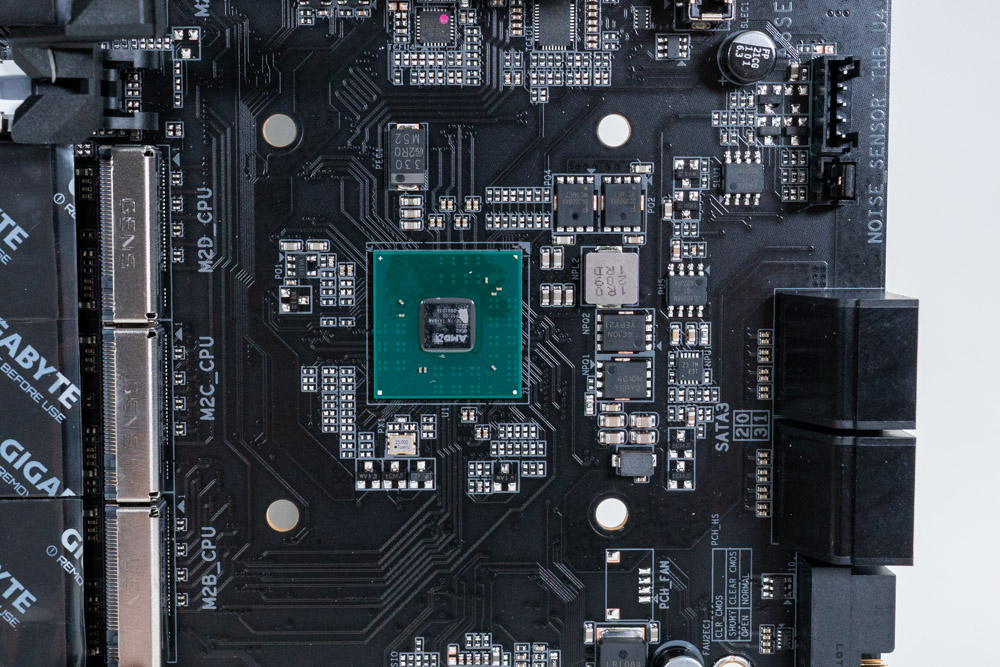
After removing the heatsink, we can get a closer look at the B650 chipset (PCH).
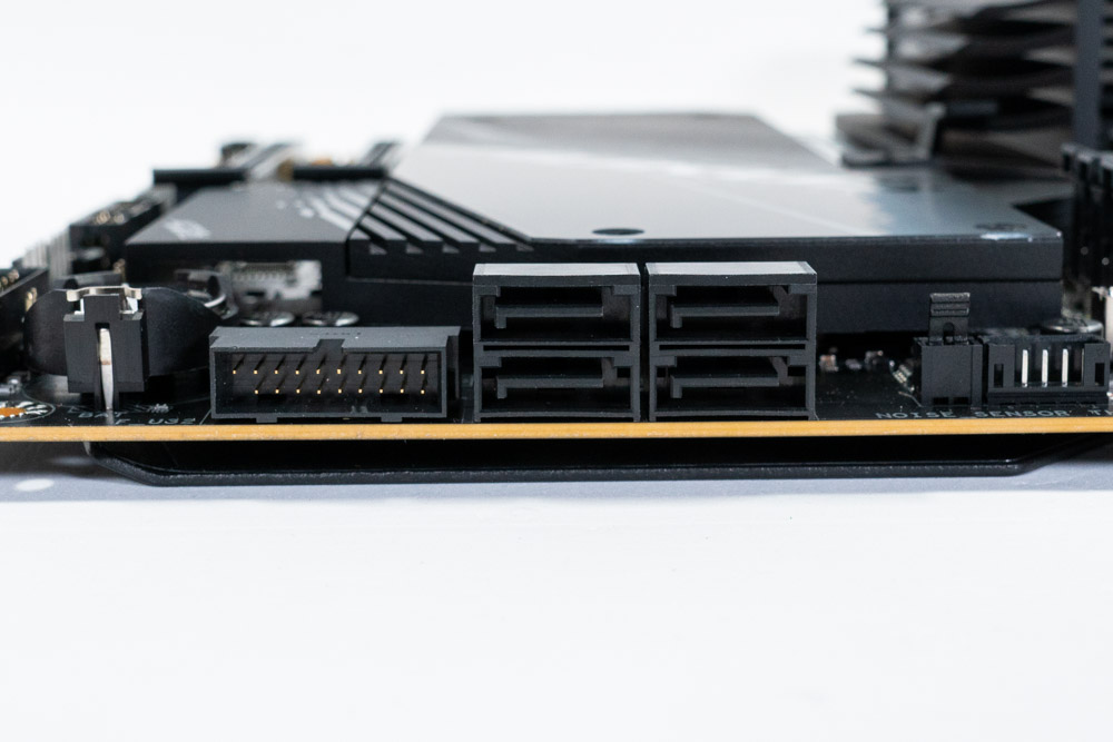
The B650E AORUS Master motherboard has a total of four 6 Gbps SATA ports, each of which are connected to the B650 Chipset (PCH).
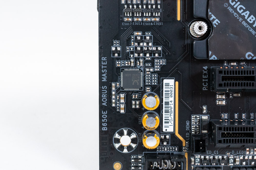
Gigabyte has used the Realtek ALC1220-VB Codec for it's on-board audio solution.
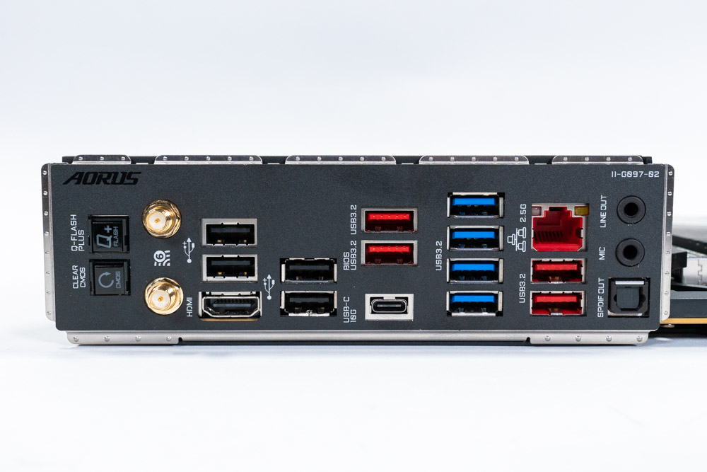
Getting a peek at the Rear IO, you can see a number of different colored USB ports. As previously stated above, the B650 chipset does not offer the same options of bandwidth for USB devices as X670/X670E. While these are indeed USB, only a few provide 10 Gb/s connections. Gigabyte also went to the trouble of adding at the Clear CMOS and the Q-Flash PLUS buttons. The Q-Flash PLUS does not require a processor or memory to work, just power supplied to the motherboard. This feature is built into the AM5 platform as well, so there's no reason for manufacturers not to take advantage of it. Additionally, there is Wi-Fi 6E and HDMI 2.1 for the onboard graphics.
- 1x Q-Flash Plus button
- 1x Clear CMOS button
- 1x HDMI 2.1 port
- 2x SMA antenna connectors (2T2R)
- 1x USB Type-C® USB 3.2 Gen 2
- 4x USB 3.2 Gen 2 Type-A ports (RED)
- 4x USB 3.2 Gen 1 ports (BLUE)
- 4x USB 2.0/1.1 ports
- 1x RJ-45 port
- 1x optical S/PDIF Out connector
- 2x audio jacks
Feb 3rd, 2025 03:01 EST
change timezone
Latest GPU Drivers
New Forum Posts
- Disabling MPO (MultiPlane Overlay) in 2025 (11)
- RTX 5080 - premature review - it sucks (260)
- Res-BAR Option on X670 AORUS ELITE AX question (1)
- Technical Issues - TPU Main Site & Forum (2025) (22)
- Using NvCleaninstall to download nvidia drivers possible? Where files saved? (1)
- Will you buy a RTX 5090? (366)
- RTX 2070 Super build (41)
- QVL - Myth, Legend, Marketing/Advertising, what is your take? (81)
- Wow YouTube is a Hog (22)
- 5090 ROG Astral LC Unboxing. (32)
Popular Reviews
- NVIDIA GeForce RTX 5080 Founders Edition Review
- Spider-Man 2 Performance Benchmark Review - 35 GPUs Tested
- MSI GeForce RTX 5080 Vanguard SOC Review
- ASUS GeForce RTX 5080 Astral OC Review
- Gigabyte GeForce RTX 5080 Gaming OC Review
- MSI GeForce RTX 5080 Suprim SOC Review
- NVIDIA DLSS 4 Transformer Review - Better Image Quality for Everyone
- Galax GeForce RTX 5080 1-Click OC Review
- ASUS GeForce RTX 5090 Astral OC Review - Astronomical Premium
- Palit GeForce RTX 5080 GameRock OC Review
Controversial News Posts
- NVIDIA 2025 International CES Keynote: Liveblog (470)
- AMD Debuts Radeon RX 9070 XT and RX 9070 Powered by RDNA 4, and FSR 4 (349)
- AMD Radeon 9070 XT Rumored to Outpace RTX 5070 Ti by Almost 15% (258)
- AMD is Taking Time with Radeon RX 9000 to Optimize Software and FSR 4 (254)
- AMD Denies Radeon RX 9070 XT $899 USD Starting Price Point Rumors (239)
- AMD Radeon RX 9070 XT & RX 9070 Custom Models In Stock at European Stores (226)
- NVIDIA GeForce RTX 5090 Features 575 W TDP, RTX 5080 Carries 360 W TDP (217)
- New Leak Reveals NVIDIA RTX 5080 Is Slower Than RTX 4090 (215)