 7
7
NZXT C1200 Gold 1200 W Review
Protection Features, Power Sequencing & EMC »Advanced Transient Response Tests
In these tests, we monitor the response of the PSU in two different scenarios. First, a transient load (15 A at +12 V, 6 A at +5 V, 6 A at +3.3 V, and 0.5 A at 5VSB) is applied to the PSU for 20 ms while it is working at 20% load. In the second scenario, the PSU, while working at 50% load, is hit by the same transient load. In both tests, our oscilloscope measures the voltage drops caused by the transient load. All voltages should remain within the regulation limits defined by the ATX specification.A PSU always operates under changing loads during real-world usage, depending on whether the CPU or graphics card is busy. It is of immense importance that the PSU can keep its rails within limits defined by the ATX specification. Smaller deviations reduce the stress applied to system components.
Note that the ATX specification requires capacitive loading during the transient tests. In our methodology, we chose to apply the worst-case scenario with no extra capacitance on the rails. Although the ATX specification asks for this capacitance, your system—the mainboard and its other parts—may not provide it, which we must also keep in mind.
| Advanced Transient Response 20% - 10 Hz | ||||
|---|---|---|---|---|
| Voltage | Before | After | Change | Pass/Fail |
| 12V | 12.147V | 11.952V | 1.60% | Pass |
| 5V | 5.020V | 4.938V | 1.64% | Pass |
| 3.3V | 3.284V | 3.178V | 3.23% | Pass |
| 5VSB | 5.007V | 4.917V | 1.80% | Pass |
| Advanced Transient Response 50% - 10 Hz | ||||
|---|---|---|---|---|
| Voltage | Before | After | Change | Pass/Fail |
| 12V | 12.082V | 12.005V | 0.63% | Pass |
| 5V | 5.011V | 4.943V | 1.35% | Pass |
| 3.3V | 3.281V | 3.173V | 3.30% | Pass |
| 5VSB | 4.991V | 4.925V | 1.32% | Pass |
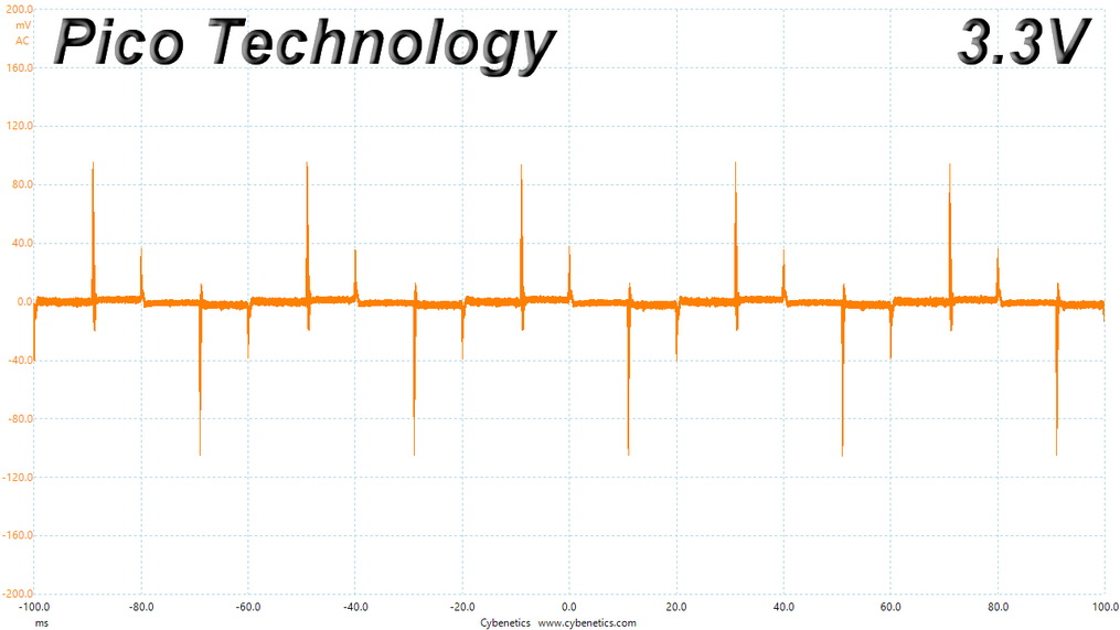
It would be nice to see close to 1% overall deviation at +12 V. Because of the light load in the 20% transient response test, where the resonant controller drives the FETs in PWM mode, the deviation is notably higher than the 50% test. In both tests, the 3.3 V rail should also keep its voltage above 3.2 V.
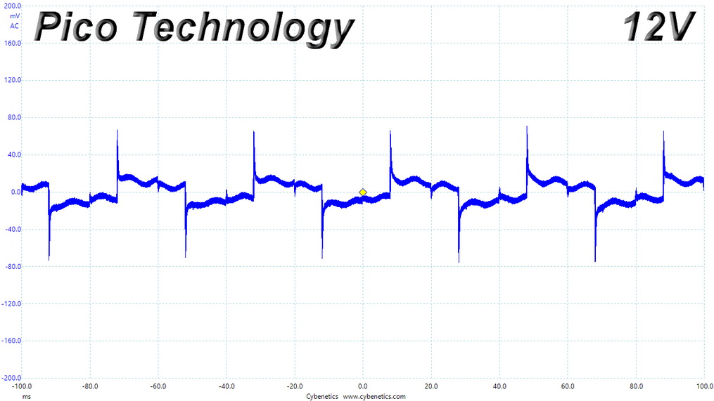
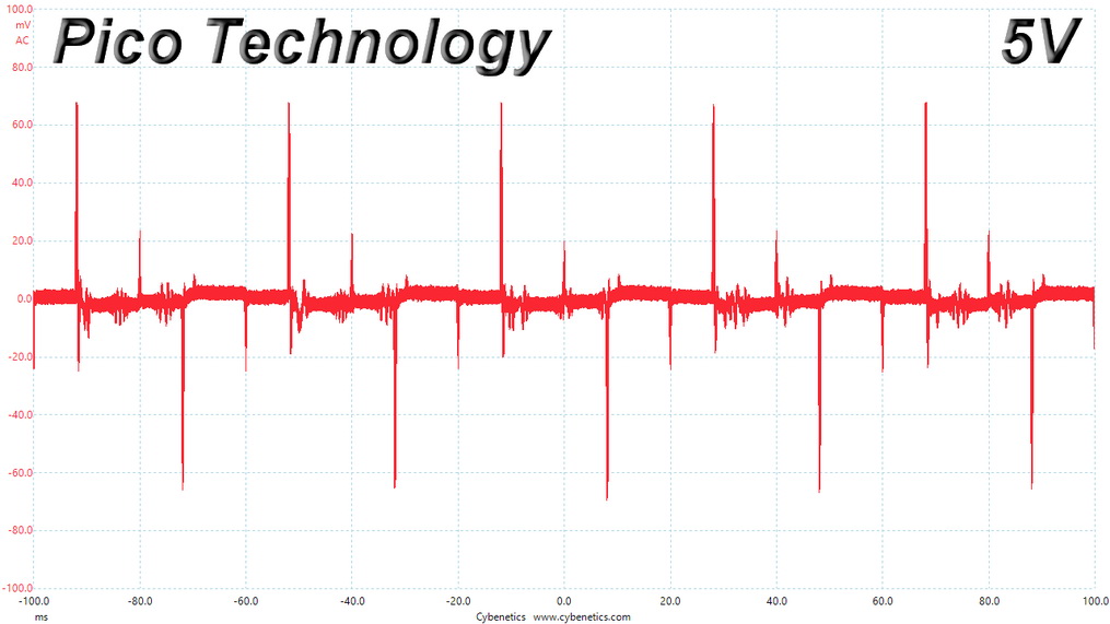
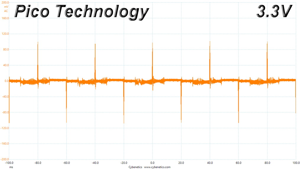
Below are the oscilloscope screenshots we took during Advanced Transient Response testing.
Transient Response at 20% Load
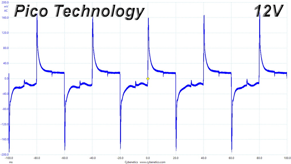
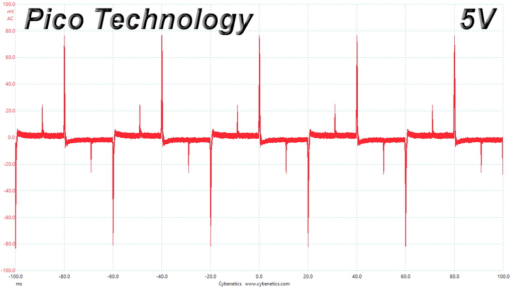
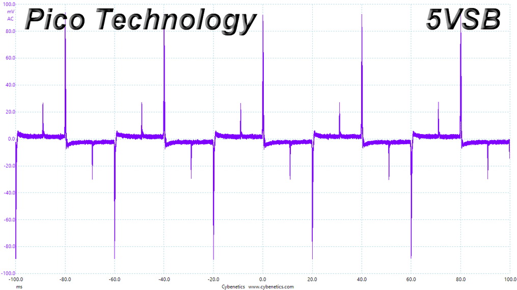
Transient Response at 50% Load
ATX 3.0 Transient Tests
Below are the requirements of the ATX 3.0 standard, according to the PSU's capacity and whether it has a 12VHPWR connector or not.| Power Excursion % of PSU Rated Size PSU <= 450 W and PSUs without 12VHPWR Connector | Power Excursion % of PSU Rated Size PSU > 450 W and 12VHPWR Connector | Time for Power Excursion (Te) | Testing Duty Cycle |
| 150% | 200% | 100 μs | 5% |
| 145% | 180% | 1 ms | 8% |
| 135% | 160% | 10 ms | 12.5% |
| 110% | 120% | 100 ms | 25% |
| 100% | 100% | Infinite | -- |
The following table shows the applied loads and the graphs depicting the results.
| Duty Cycle | Time for Power Excursion (Te) | Time Constant (Tc) | Power @ Te | Power @ Tc |
| 5% | 100 μs | 1900 μs | 3300 W | 1514.1 W |
| 8% | 1 ms | 11.5 ms | 2970 W | 1480.6 W |
| 12.5% | 10 ms | 70 ms | 2640 W | 1454.6 W |
| 25% | 100 ms | 300 ms | 1980 W | 1524.2 W |
The PSU passed all tests successfully, with the extra capacitance the ATX 3.0 spec requires. Still, the 3.3 V rail was at the limit. With 0.01 V lower voltage in the 200% transient load test, it would fail.
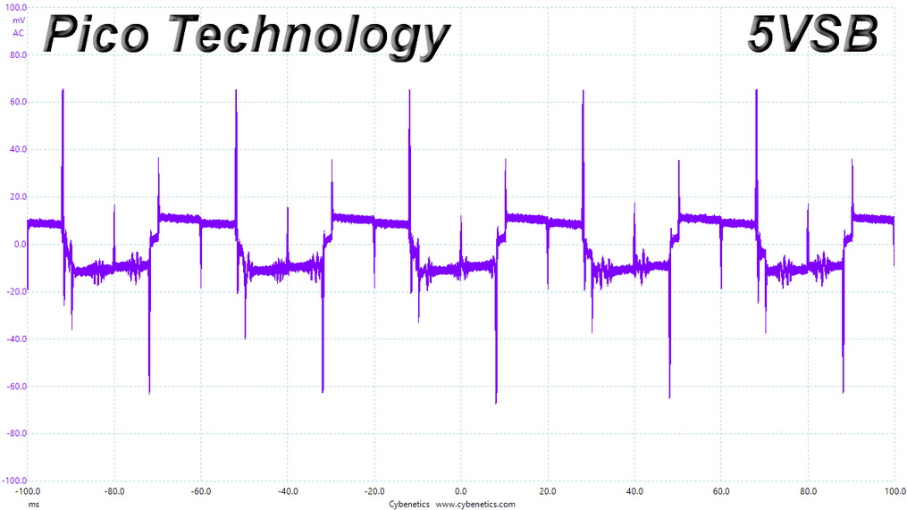
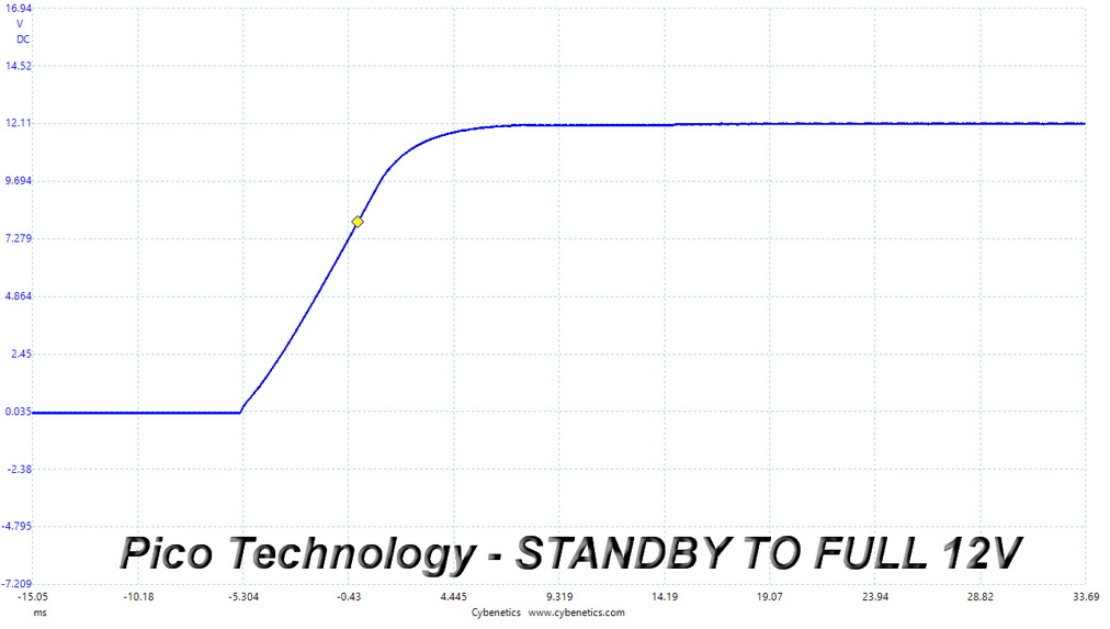
Turn-On Transient Tests
We measure the response of the PSU in more straightforward scenarios of transient load—during the power-on phase of the PSU—in the next set of tests. In the first test, we turn the PSU off, dial the maximum current the 5VSB can output, then switch on the PSU. In the second test, we dial the maximum load +12 V can handle and start the PSU while the PSU is in standby mode. In the last test, while the PSU is completely switched off (we cut off power or switch the PSU off by flipping its on/off switch), we dial the maximum load the +12 V rail can handle before switching the PSU on from the loader and restoring power. The ATX specification states that recorded spikes on all rails should not exceed 10% of their nominal values (e.g., +10% for +12 V is 13.2 V and 5.5 V for +5V).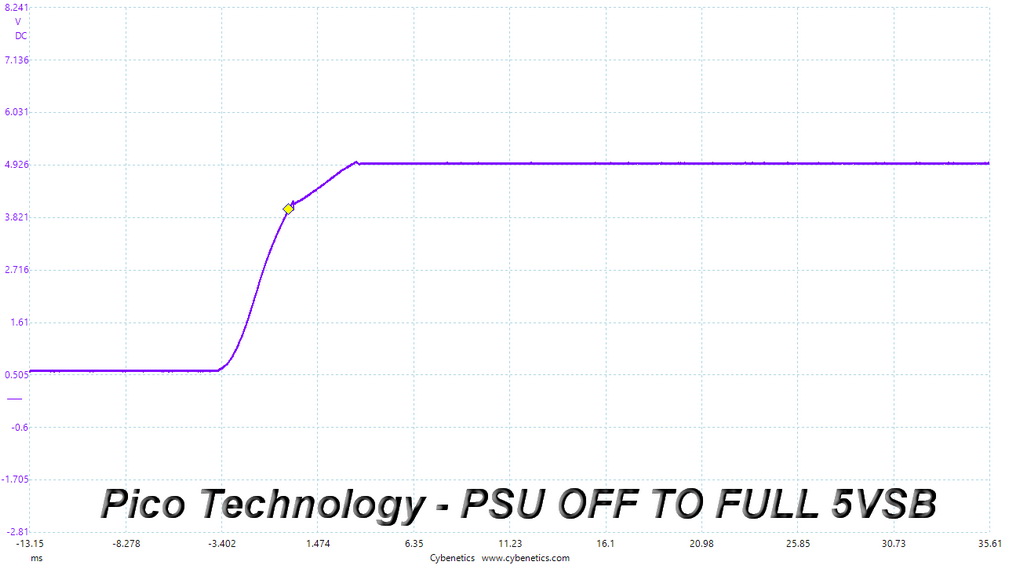
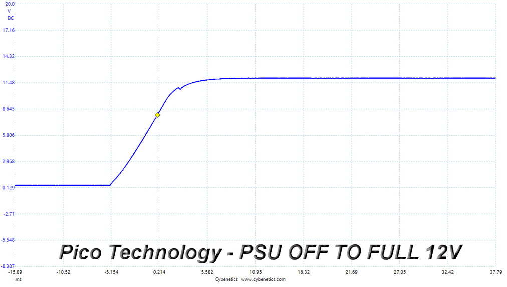
I noticed a tiny voltage drop during the "PSU Off to Full 12 V" test, which is highly unlikely to create any problems.
Inrush Current
Inrush current, or switch-on surge, refers to the maximum, instantaneous input current drawn by an electrical device when it is first turned on. If high enough, inrush current can cause the tripping of circuit breakers and fuses, and may also damage switches, relays, and bridge rectifiers. As a result, the lower the inrush current of a PSU right as it is turned on, the better.
Inrush current is at the typical levels, with 230 V input.
Leakage Current
We use a GW Instek GPT-9904 electrical safety tester to measure the leakage current. According to the IEC-60950-1 regulation, no power supply should exceed 3.5 mA of leakage current, which is low enough not to harm anyone touching the chassis. This test is performed at 110% of the rated input voltage.
Leakage current is low.
Mar 12th, 2025 09:03 EDT
change timezone
Latest GPU Drivers
New Forum Posts
- Silent Hill Series Discussion/Speculation thread (3)
- Nvidia's GPU market share hits 90% in Q4 2024 (gets closer to full monopoly) (874)
- Just for Information: Windows AMD GPU Driver offline package not really offline package with active internet connection (7)
- MorePowerTool for RDNA 4. (2)
- Cant Enable Resizable Bar (4)
- As we live the age of game remakes, which game you would like to see to have a remake? (366)
- Cant read/flash bios of Asus RX 6700 TUF with amdvbflash (8)
- Packet Loss after updating to windows 11 (4)
- Post your Old CDs & FDs, from back in the day thread. (60)
- AMD RX 9070 XT & RX 9070 non-XT thread (OC, undervolt, benchmarks, ...) (22)
Popular Reviews
- AMD Ryzen 9 9950X3D Review - Great for Gaming and Productivity
- XFX Radeon RX 9070 XT Mercury OC Magnetic Air Review
- Sapphire Radeon RX 9070 XT Nitro+ Review - Beating NVIDIA
- ASUS Radeon RX 9070 TUF OC Review
- Dough Spectrum Black 32 Review
- MSI MAG B850 Tomahawk Max Wi-Fi Review
- AMD Ryzen 7 9800X3D Review - The Best Gaming Processor
- NVIDIA GeForce RTX 5070 Founders Edition Review
- Corsair Vengeance RGB CUDIMM DDR5-8800 48 GB CL42 Review
- XPG Starker Air BTF Review
Controversial News Posts
- NVIDIA GeForce RTX 50 Cards Spotted with Missing ROPs, NVIDIA Confirms the Issue, Multiple Vendors Affected (513)
- AMD Radeon RX 9070 and 9070 XT Listed On Amazon - One Buyer Snags a Unit (261)
- AMD RDNA 4 and Radeon RX 9070 Series Unveiled: $549 & $599 (260)
- AMD Mentions Sub-$700 Pricing for Radeon RX 9070 GPU Series, Looks Like NV Minus $50 Again (248)
- NVIDIA Investigates GeForce RTX 50 Series "Blackwell" Black Screen and BSOD Issues (244)
- AMD Radeon RX 9070 and 9070 XT Official Performance Metrics Leaked, +42% 4K Performance Over Radeon RX 7900 GRE (195)
- AMD Radeon RX 9070-series Pricing Leaks Courtesy of MicroCenter (158)
- AMD Radeon RX 9070 XT Could Get a 32 GB GDDR6 Upgrade (100)