 0
0
OCZ ZX Series 1250 W Review
Ripple Measurements »Advanced Transient Response Tests
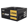
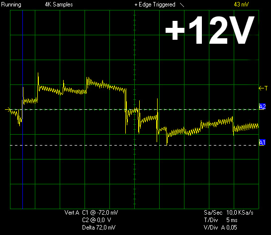
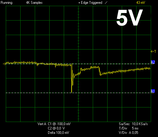
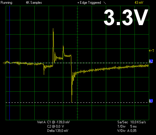
In these tests we monitor the response of the PSU in two different scenarios. First a transient load (10A at +12V, 5A at 5V and 6A at 3.3V) is applied for 50 ms to the PSU, while the latter is working at a 20% load state. In the second scenario the PSU, while working with 50% load, is hit by the same transient load (with the exception now that load at 3.3V is increased by 4A). In both tests, we measure the voltage drops that the transient load causes, using a Labjack that is attached to our loader and the Stingray oscilloscope. In any case voltages should remain within the regulation limits specified by the ATX specification. We must stress here, that the above tests are crucial, since they simulate transient loads that a PSU is very likely to handle (e.g. starting of a RAID array, an instant 100% load of CPU/VGAs etc.) We call these tests “Advanced Transient Response Tests” and they are designed to be very tough to master, especially for PSUs with capacities lower than 500W.| Advanced Transient Response 20% | ||||
|---|---|---|---|---|
| Voltage | Before | After | Change | Pass/Fail |
| 12 V | 12.158V | 12.118V | 0.33% | Pass |
| 5 V | 5.076V | 5.013V | 1.24% | Pass |
| 3.3 V | 3.295V | 3.205V | 2.73% | Pass |
| 5VSB | 5.067V | 5.032V | 0.69% | Pass |
| Advanced Transient Response 50% | ||||
|---|---|---|---|---|
| Voltage | Before | After | Change | Pass/Fail |
| 12 V | 12.067V | 11.995V | 0.60% | Pass |
| 5 V | 5.005V | 4.905V | 2.00% | Pass |
| 3.3 V | 3.236V | 3.097V | 4.30% | Fail |
| 5VSB | 5.032V | 4.997V | 1.39% | Pass |
Voltage drops on the +12V and 5V rails are low. Especially the +12V rail performed really well. For a PSU that can handle over 100A at +12V this comes sort of natural. On the contrary 3.3V failed to pass the really tough second part of the tests, but this happened mainly because of the already low voltage of the specific rail and not due to a high voltage drop.
Below you will find the oscilloscope screenshots that we took during Advanced Transient Response Testing.
Transient Response at 20% Load
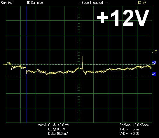
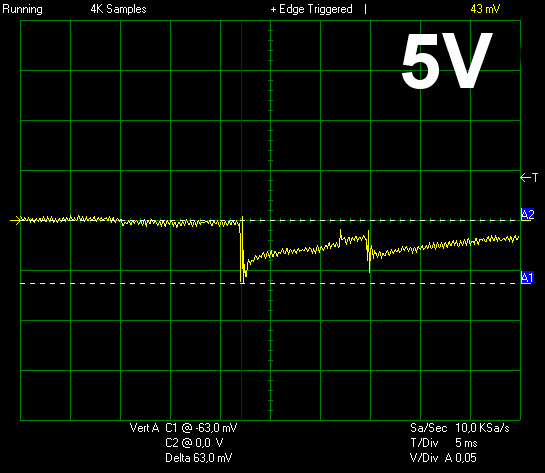
Transient Response at 50% Load
Turn-On Transient Tests
In the next set of tests we measure the response of the PSU in simpler scenarios of transient loads, during the turn on phase of the PSU. In the first test we turn off the PSU, dial 2A load at 5VSB and then switch on the PSU. In the second test, while the PSU is in standby, we dial the maximum load that +12V can handle and we start the PSU. In the last test, while the PSU is completely switched off (we cut off power or switch off the PSU's On/Off switch), we dial the maximum load that +12V can handle and then we switch on the PSU from the loader and we restore power. The ATX specification states that recorded spikes on all rails should not exceed 10% of their nominal values (e.g. +10% for 12V is 13.2V and for 5V is 5.5V).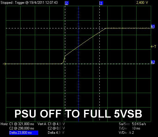
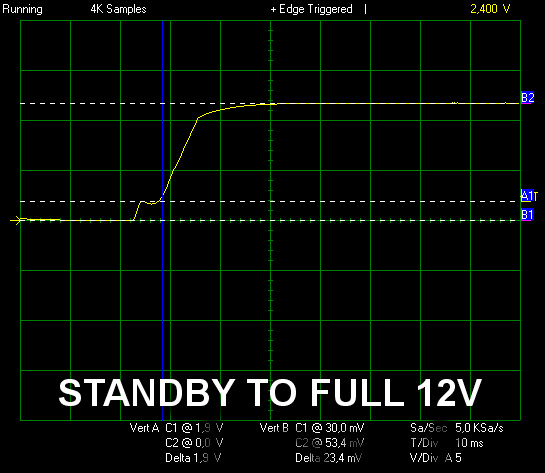
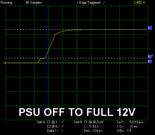
At 5VSB we did not notice any voltage overshoots but the rise time* is a little above the 20ms limit that the ATX specification sets, however this is not something to worry about. At the other two tests we also didn't encounter any voltage overshoots, but the slope of +12V in both cases is not smooth and at 1.7-1.9V it not only stalls but for a few ms it turns to negative. ATX specification states that "the smooth turn-on requires that, during the 10% to 90% portion of the rise time, the slope of the turn-on waveform must be positive" so this is a problem, however not dead serious since we shouldn't forget that in both tests we draw almost 100A from the +12V line, a very high load.
*Rise time is defined as the time it takes any output voltage to rise from 10% to 95% of its nominal voltage.
Feb 21st, 2025 05:32 EST
change timezone
Latest GPU Drivers
New Forum Posts
- V Rising Lycanthropy Club (21)
- What are you playing? (22962)
- [PCGamer] Former Sony exec finally says the quiet part out loud: putting PlayStation games on PC is 'almost like printing money' (29)
- Why Doesn't AMD Offer Long-Term GPU Availability Like Nvidia? (12)
- 3D Printer Club (424)
- Get ready to open your wallets people (44)
- Dune: Awakening benchmark - post your results (0)
- Will undervolting a 4090 keep the connector from melting? A discussion about electrical theory. (22)
- Should I make a thermal maintenance on my GPU? (67)
- Free Games Thread (4481)
Popular Reviews
- MSI GeForce RTX 5070 Ti Ventus 3X OC Review
- Gigabyte GeForce RTX 5090 Gaming OC Review
- Galax GeForce RTX 5070 Ti 1-Click OC White Review
- ASUS GeForce RTX 5070 Ti TUF OC Review
- Ducky One X Inductive Keyboard Review
- MSI GeForce RTX 5070 Ti Vanguard SOC Review
- AMD Ryzen 7 9800X3D Review - The Best Gaming Processor
- MSI GeForce RTX 5070 Ti Gaming Trio OC+ Review
- MSI MAG Z890 Tomahawk Wi-Fi Review
- NVIDIA GeForce RTX 5080 Founders Edition Review
Controversial News Posts
- AMD Radeon 9070 XT Rumored to Outpace RTX 5070 Ti by Almost 15% (302)
- AMD Plans Aggressive Price Competition with Radeon RX 9000 Series (257)
- AMD is Taking Time with Radeon RX 9000 to Optimize Software and FSR 4 (256)
- AMD Radeon RX 9070 and 9070 XT Listed On Amazon - One Buyer Snags a Unit (242)
- Edward Snowden Lashes Out at NVIDIA Over GeForce RTX 50 Pricing And Value (241)
- AMD Denies Radeon RX 9070 XT $899 USD Starting Price Point Rumors (239)
- New Leak Reveals NVIDIA RTX 5080 Is Slower Than RTX 4090 (215)
- AMD Radeon RX 9070 XT Launch Allegedly Set for March 6 (152)