 3
3
Scythe Chouriki 2 Plug-In 850 W Review
Voltage Regulation & Efficiency »A Look Inside
Before reading this page we strongly suggest to take a look at this article, which will help you understand the internal components of a PSU much better.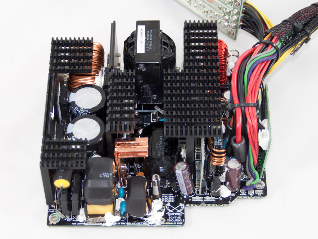
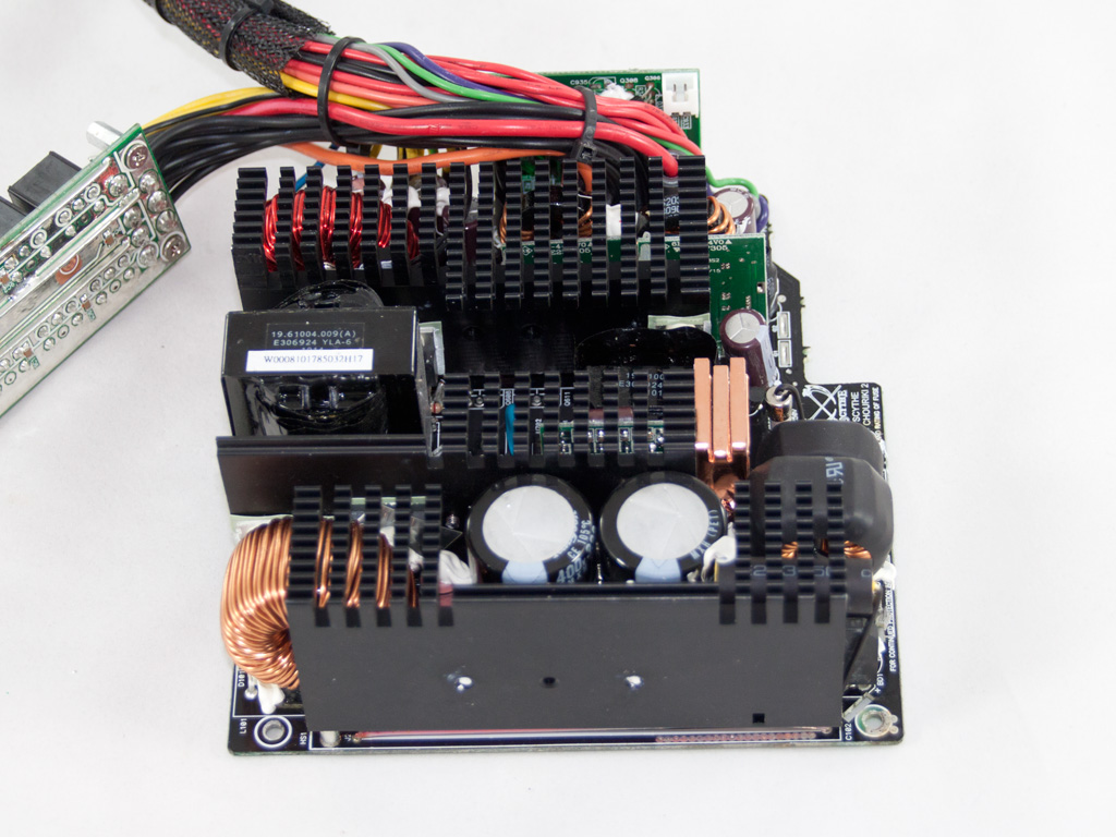
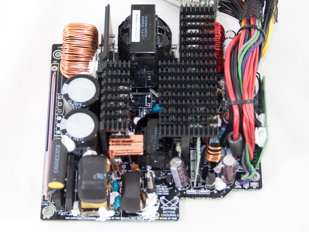
The OEM of this unit is Highpower/Sirtec and this platform, with some component changes to achieve higher efficiency, was also used in the older OCZ Z series 850W PSU so it's not so new. Since one of the heatsinks blocked the view we removed it.
As usual the transient filtering stage starts at the AC receptacle. There we find one X and two Y caps. It continues on the main PCB with two coils, two Y and one X caps and an MOV. All in all we have a complete transient filtering stage so let's move on.
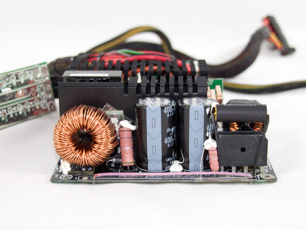
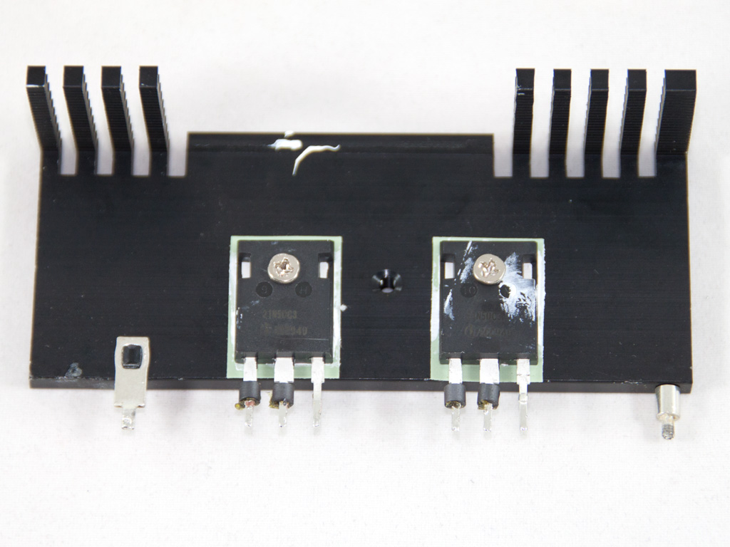
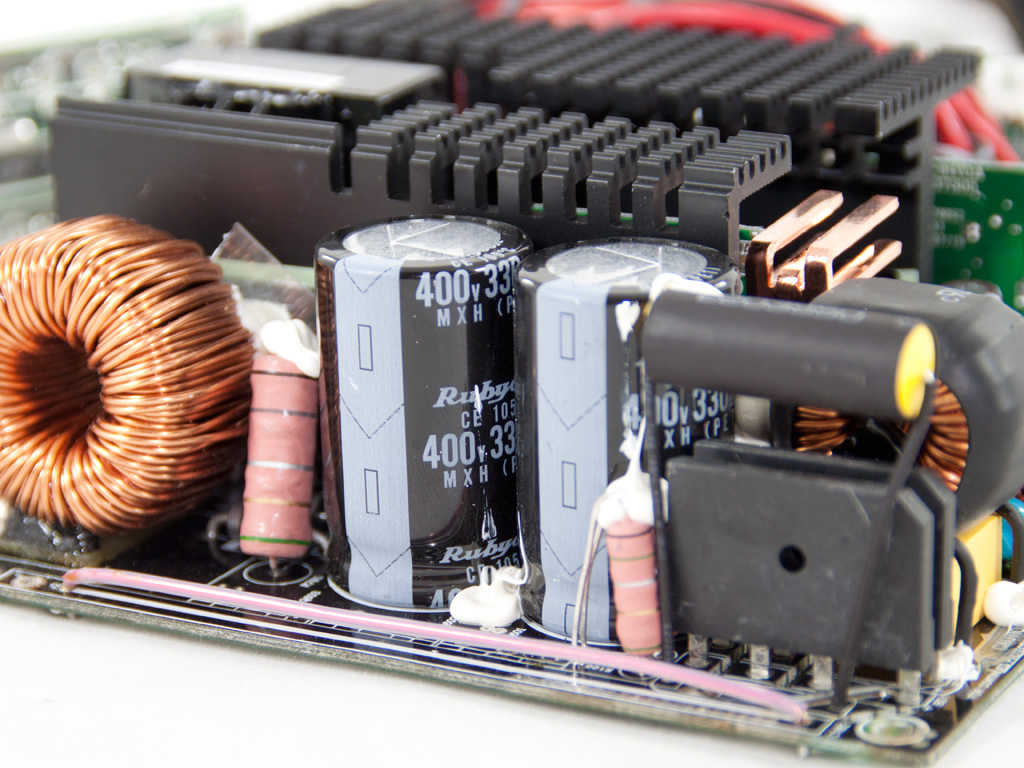
The bridge rectifiers are two GBJ 1506, which are not attached to a heatsink. In the APFC two SPW21Ν50C3 mosfets are used along with two boost diodes. On the PCB there is place for an addition APFC mosfet. The reservoir/smoothing capacitors are two, parallel installed, Rubycons (330 μF, 400 V, 105°C). As main switches we find two SPW21N50C3 again on a double switch forward topology.
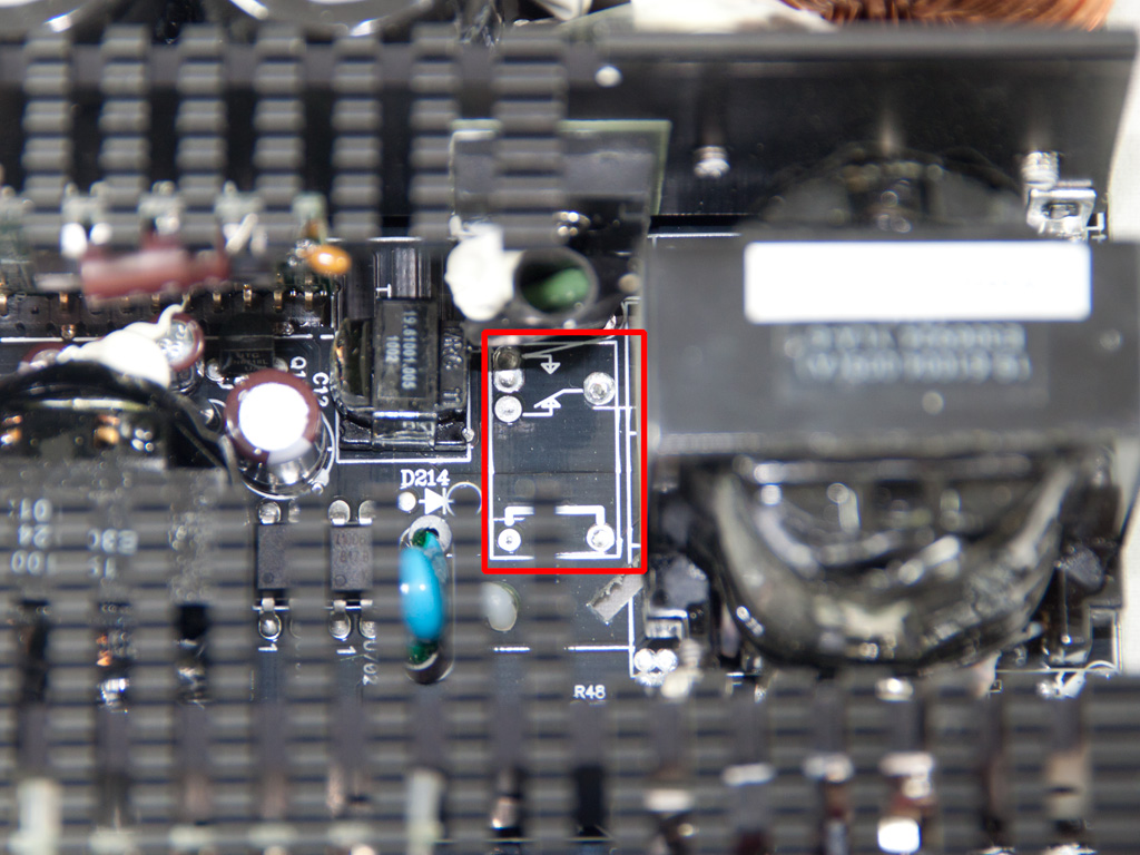
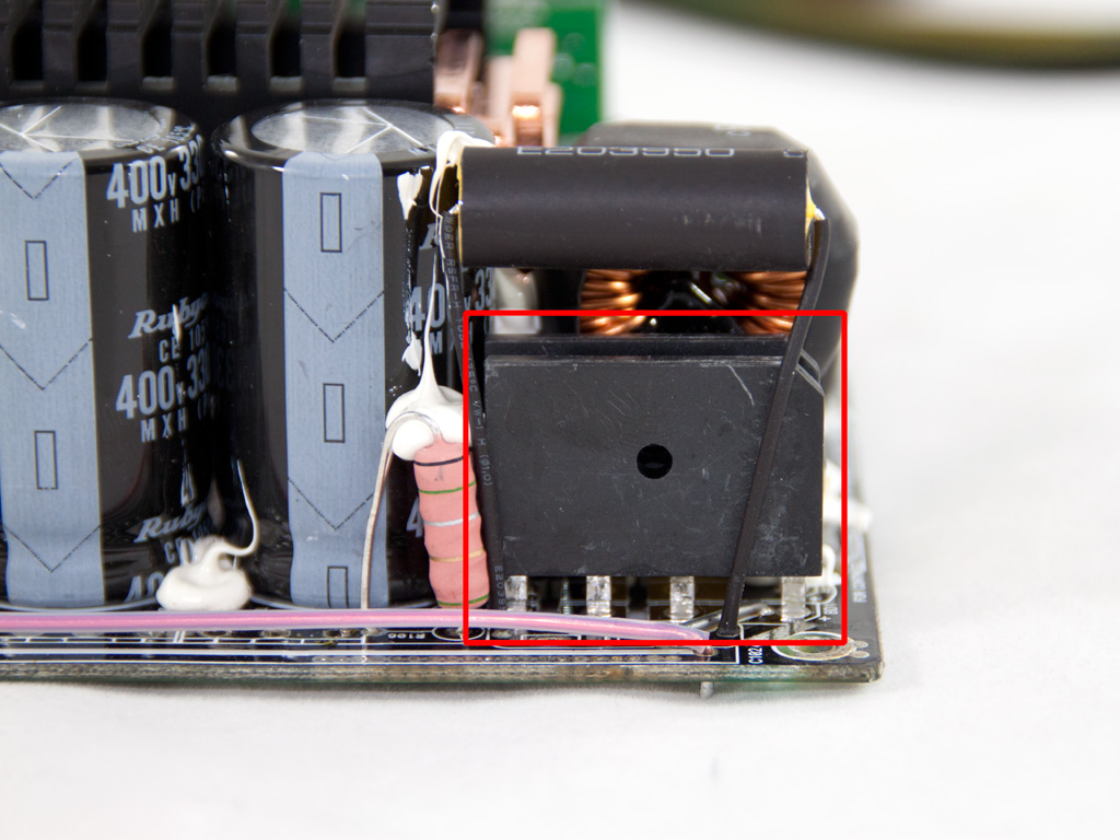
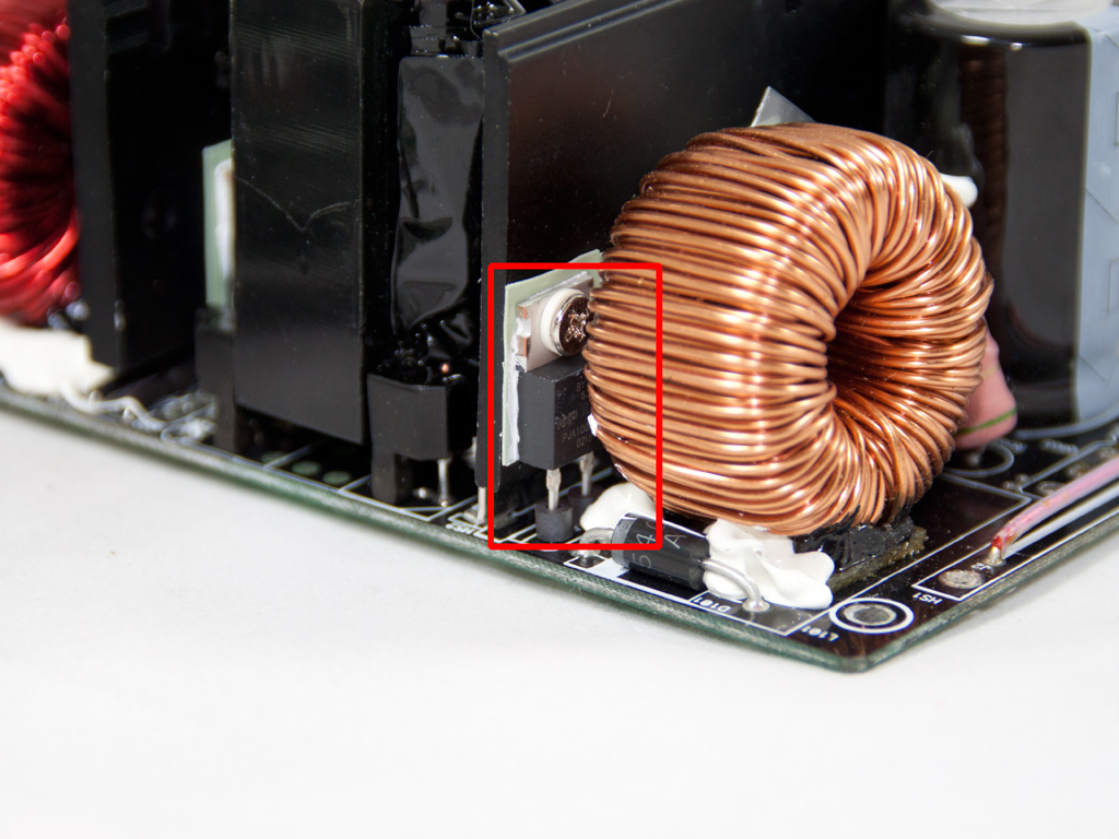
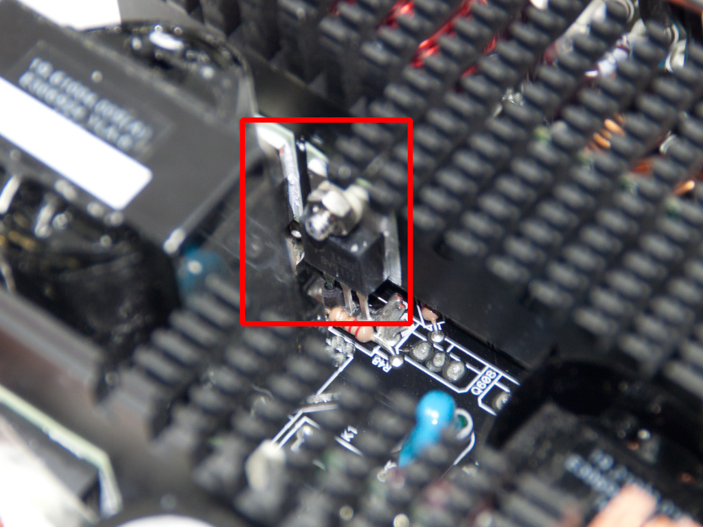
The inrush current protection thermistor is located right next to one of the two primary switches. Although there is place on the main PCB for the bypass electromagnetic relay it's left empty. That's a shame because this would benefit efficiency and the thermistor would be in the right temperature/resistance even while the PSU was operating.
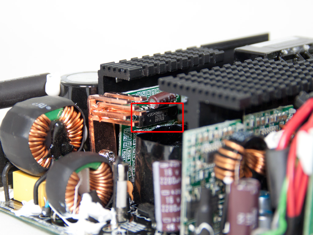
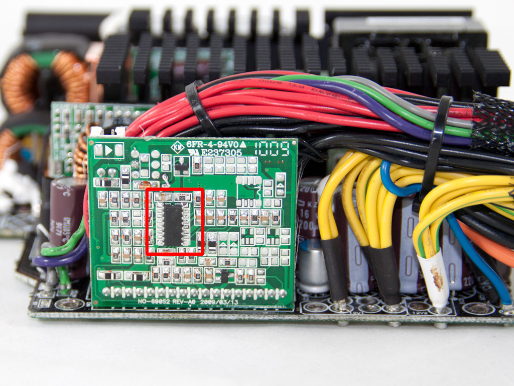
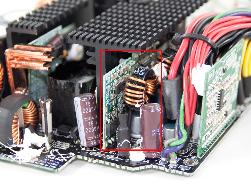
The PFC/PWM controller is the famous CM6800, which resides on a vertical daughter-board near the primary heatsink. Housekeeping jobs are done by a PS224 IC, which supports two +12V OCP channels, matching this way the +12V virtual rails of the PSU. Since this IC does not support OTP it's highly possible the PSU uses an external circuit to implement this protection.
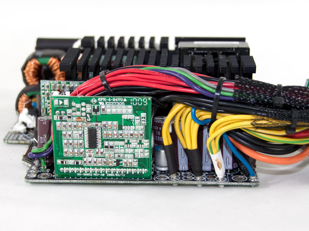
In the secondary side synchronous design is used so instead of SBRs (Schottky Barrier Rectifiers) mosfets are used. The +12V are generated by four mosfets. The minor rails are generated from +12V through two DC-DC voltage regulation modules. Each VRM carries four IPD060N03L mosfets and an APW7073 PWM controller. Finally, all capacitors in the secondary side are provided by Nippon Chemi-Con.
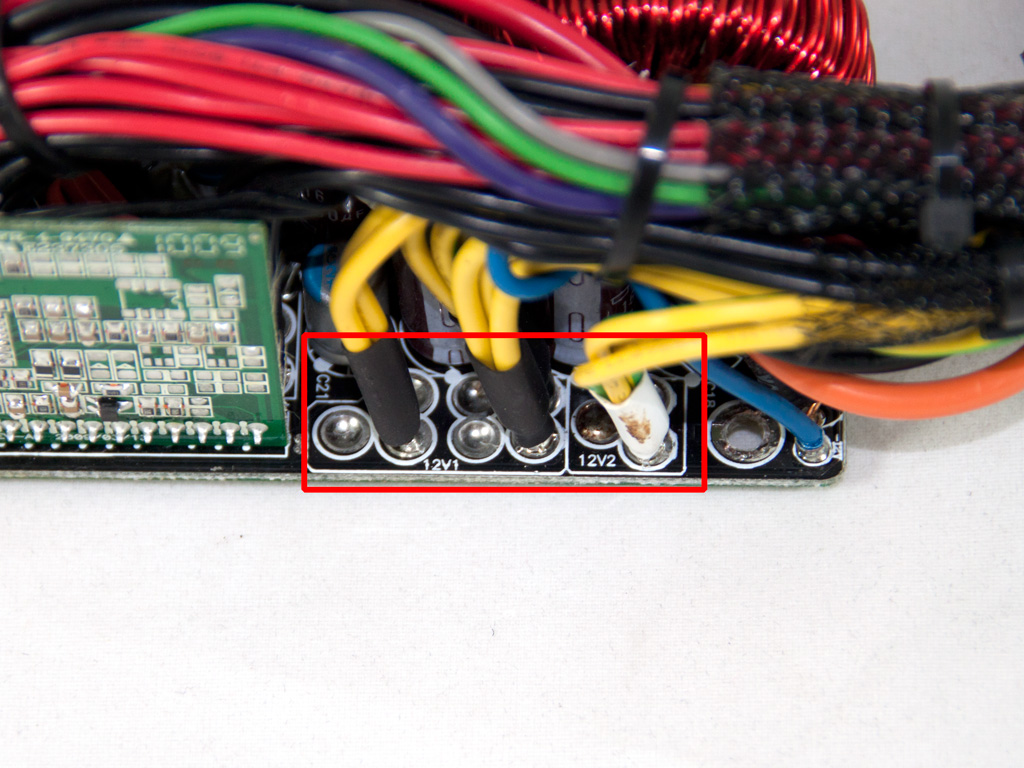
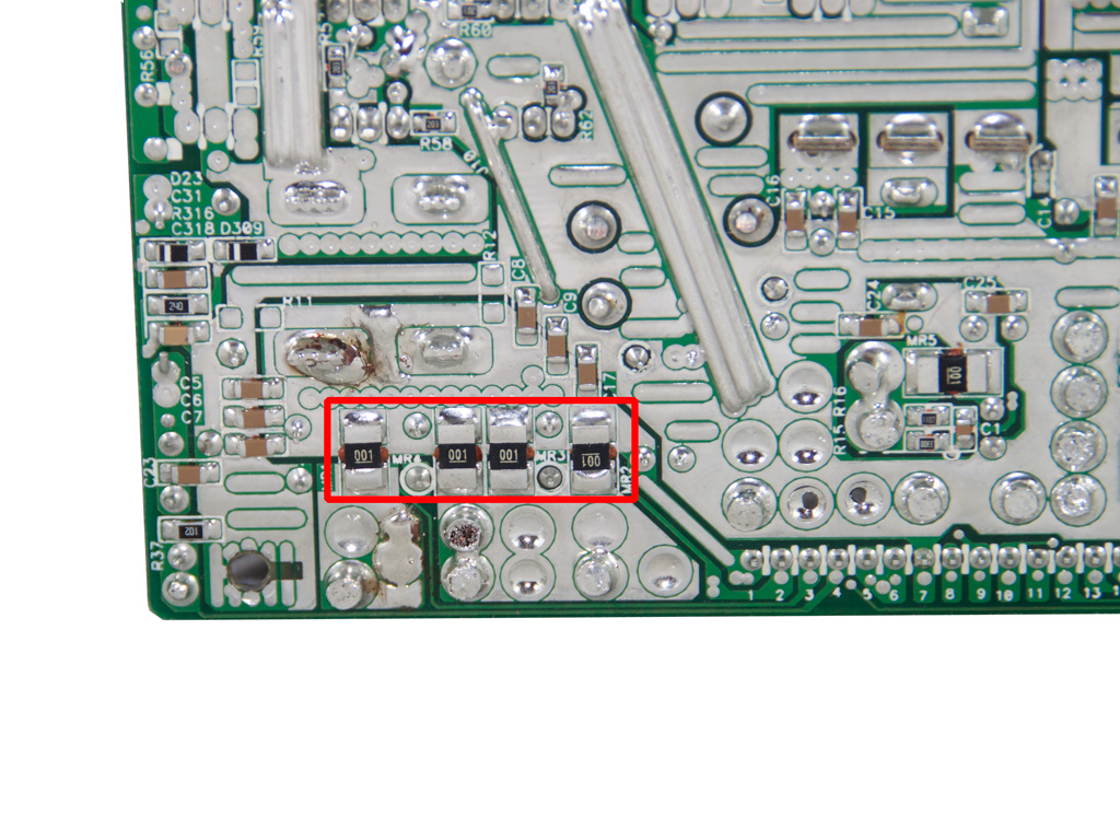
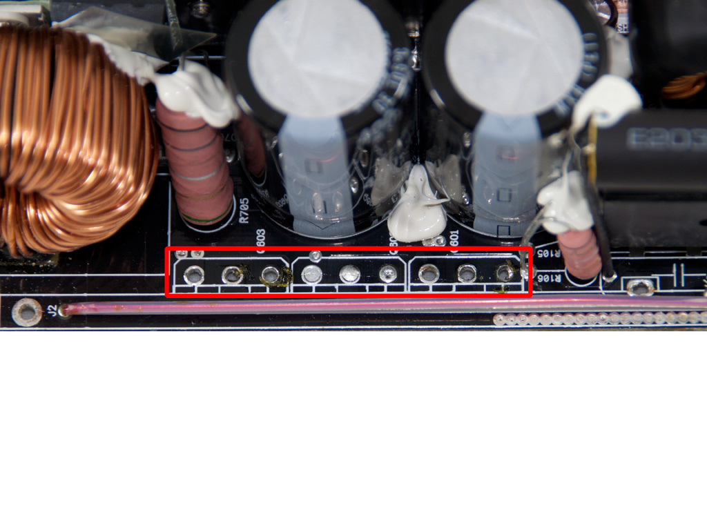
Although the PSU has two +12V rails on the solder side of the main PCB we find four shunt resistors and there is place for another two. So this platform is able to support up to six +12V rails.
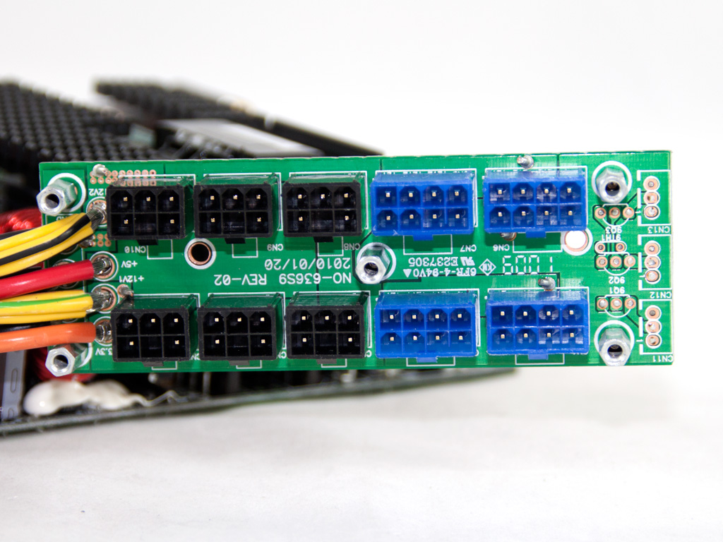
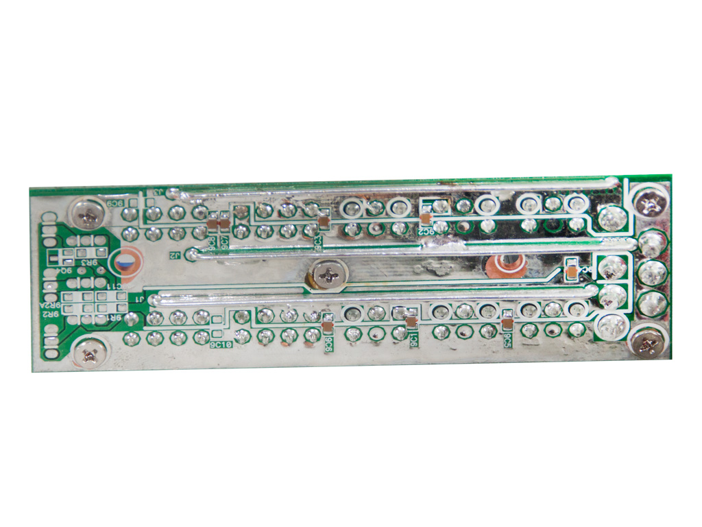
The modular PCB does not have any capacitors installed for current ripple filtering. Too bad because as you will see later they would be handy. Also soldering quality here is mediocre.
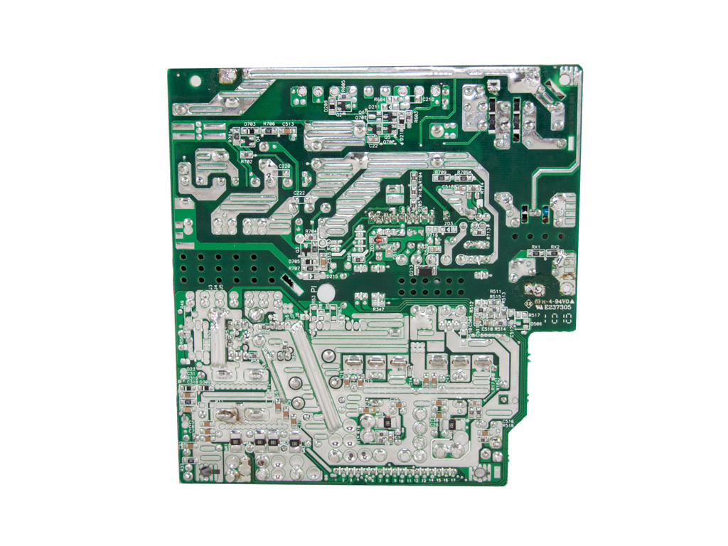
Soldering quality on the main PCB is quite good. Most of the joints have good appearance, proper wetting and the right amount of solder.
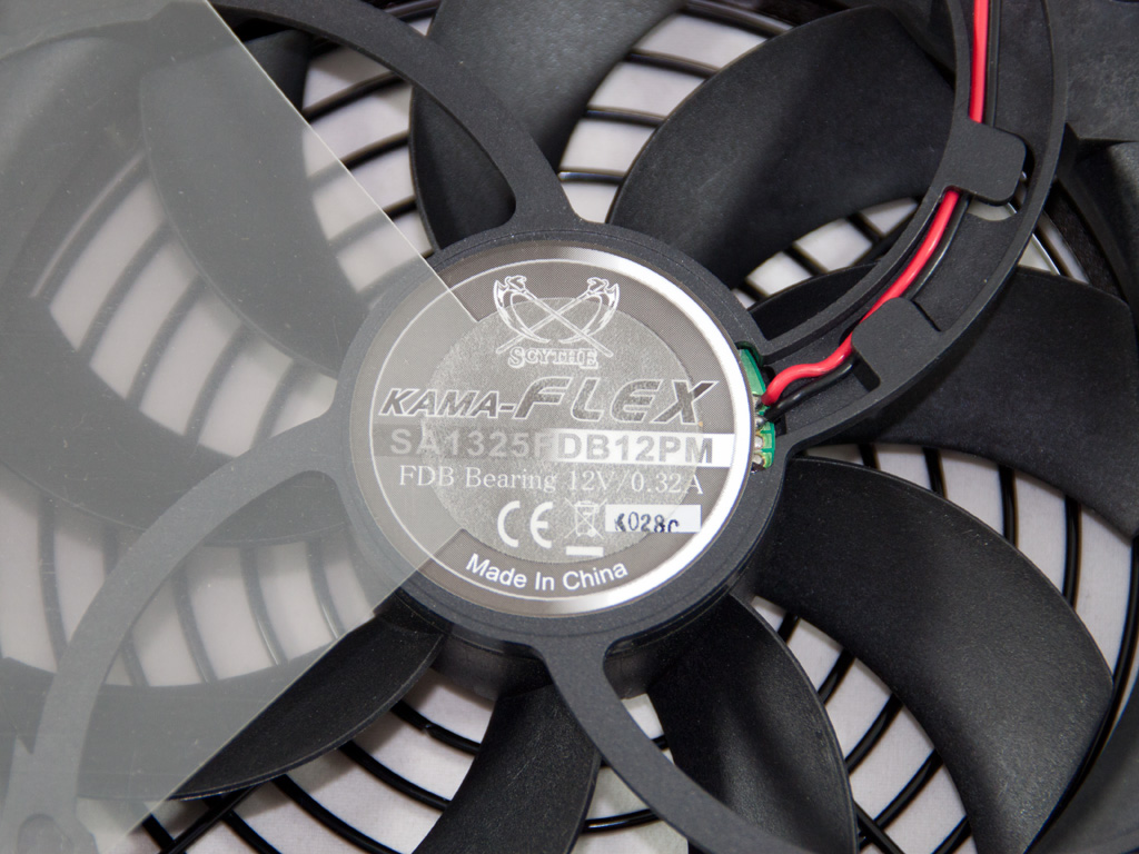
The cooling fan is provided of course by Scythe (135mm Kama Flex with S-FDB bearing) and its model number is SA1325FDB12PM (1,300 rpm max, 6.7 - 20.9 dBA noise level, 120,000 Hours MTBF).
Mar 10th, 2025 19:11 EDT
change timezone
Latest GPU Drivers
New Forum Posts
- Post Your TIMESPY, PCMARK10 & FIRESTRIKE SCORES! (2019) (271)
- AMD RX 7000 series GPU Owners' Club (1307)
- I need a BIOS for the "Rx580 8gb" chip 215-0876406 (6)
- Biostar RX 6700 XT OC BIOS (7)
- Nvidia's GPU market share hits 90% in Q4 2024 (gets closer to full monopoly) (774)
- What's your latest tech purchase? (23278)
- Wherein lies the difference (2)
- USB hard disk box capacity limits (14)
- RX 9000 series GPU Owners Club (41)
- Gaming PC instabiliity (22)
Popular Reviews
- Sapphire Radeon RX 9070 XT Nitro+ Review - Beating NVIDIA
- XFX Radeon RX 9070 XT Mercury OC Magnetic Air Review
- ASUS Radeon RX 9070 TUF OC Review
- MSI MAG B850 Tomahawk Max Wi-Fi Review
- NVIDIA GeForce RTX 5080 Founders Edition Review
- NVIDIA GeForce RTX 5070 Founders Edition Review
- Corsair Vengeance RGB CUDIMM DDR5-8800 48 GB CL42 Review
- AMD Ryzen 7 9800X3D Review - The Best Gaming Processor
- ASUS GeForce RTX 5070 Ti TUF OC Review
- MSI GeForce RTX 5070 Ti Gaming Trio OC+ Review
Controversial News Posts
- NVIDIA GeForce RTX 50 Cards Spotted with Missing ROPs, NVIDIA Confirms the Issue, Multiple Vendors Affected (513)
- AMD Plans Aggressive Price Competition with Radeon RX 9000 Series (277)
- AMD Radeon RX 9070 and 9070 XT Listed On Amazon - One Buyer Snags a Unit (261)
- AMD RDNA 4 and Radeon RX 9070 Series Unveiled: $549 & $599 (260)
- AMD Mentions Sub-$700 Pricing for Radeon RX 9070 GPU Series, Looks Like NV Minus $50 Again (248)
- NVIDIA Investigates GeForce RTX 50 Series "Blackwell" Black Screen and BSOD Issues (244)
- AMD Radeon RX 9070 and 9070 XT Official Performance Metrics Leaked, +42% 4K Performance Over Radeon RX 7900 GRE (195)
- AMD Radeon RX 9070-series Pricing Leaks Courtesy of MicroCenter (158)