 7
7
Silverstone Strider Gold ST65F-G 650 W Review
Ripple Measurements »Advanced Transient Response Tests
In these tests, we monitor the response of the PSU in two different scenarios. First, a transient load (10 A at +12V, 5 A at 5V, 5 A at 3.3V, and 0.5 A at 5VSB) is applied to the PSU for 200 ms while the latter is working at a 20% load state. In the second scenario, the PSU, while working at 50% load, is hit by the same transient load. In both tests, we measure the voltage drops that the transient load causes using our oscilloscope. The voltages should remain within the regulation limits defined by the ATX specification. We must stress here that the above tests are crucial since they simulate transient loads that a PSU is very likely to handle (e.g., booting a RAID array, an instant 100% load of CPU/VGAs, etc.). We call these tests "Advanced Transient Response Tests", and they are designed to be very tough to master, especially for PSUs with capacities lower than 500 W.| Advanced Transient Response 20% | ||||
|---|---|---|---|---|
| Voltage | Before | After | Change | Pass/Fail |
| 12 V | 12.051V | 11.884V | 1.39% | Pass |
| 5 V | 5.034V | 4.848V | 3.69% | Pass |
| 3.3 V | 3.377V | 3.237V | 4.15% | Pass |
| 5VSB | 5.081V | 5.036V | 0.89% | Pass |
| Advanced Transient Response 50% | ||||
|---|---|---|---|---|
| Voltage | Before | After | Change | Pass/Fail |
| 12 V | 11.991V | 11.808V | 1.53% | Pass |
| 5 V | 4.998V | 4.852V | 2.92% | Pass |
| 3.3 V | 3.344V | 3.201V | 4.28% | Pass |
| 5VSB | 5.037V | 4.985V | 1.03% | Pass |
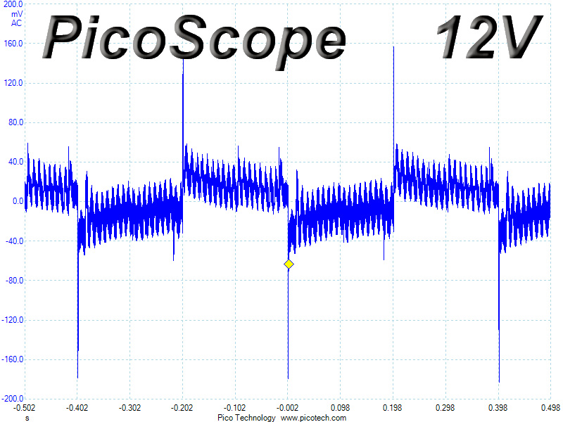
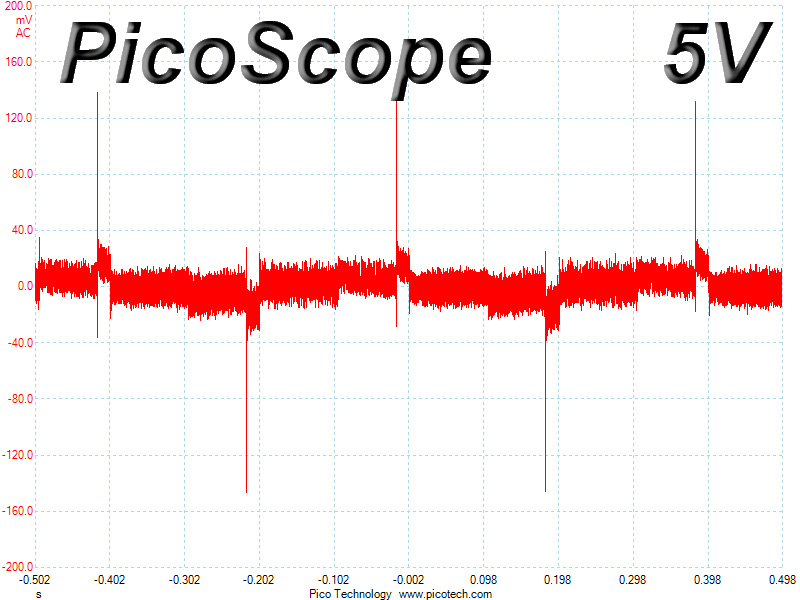
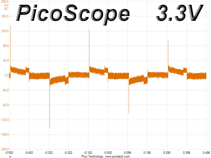
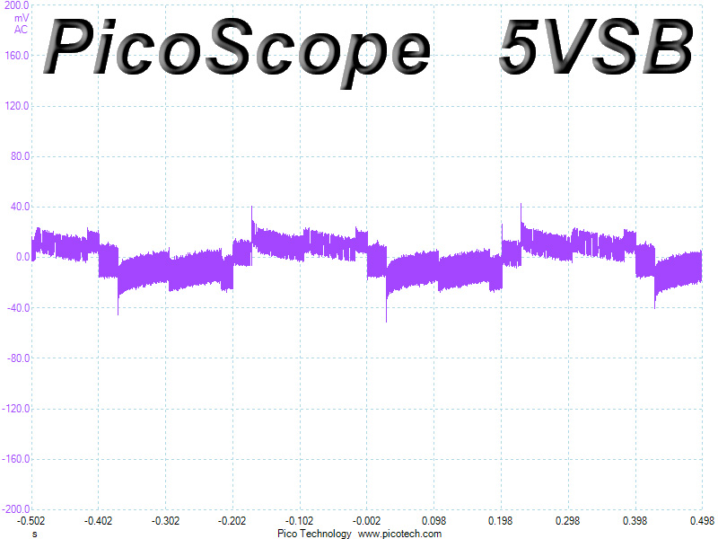
On the +12V rail, the deviation is not high, but the voltage fell to almost 11.8 V during the second test. On the minor rails, we measured larger deviations, with voltage on the 3.3V rail falling to almost 3.2 V during the second test. Thankfully, we didn't measure readings below 3.2 V on the 3.3V rail. Finally, 5VSB registered the smallest deviations of all rails; its voltage was very close to the nominal value in both cases.
Below, you will find the oscilloscope screenshots that we took during Advanced Transient Response Testing.
Transient Response at 20% Load
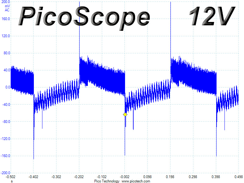
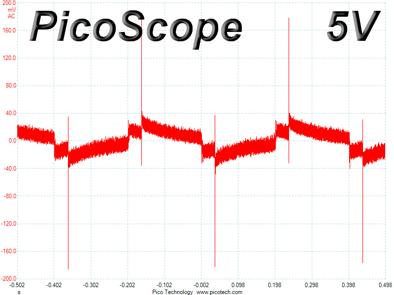
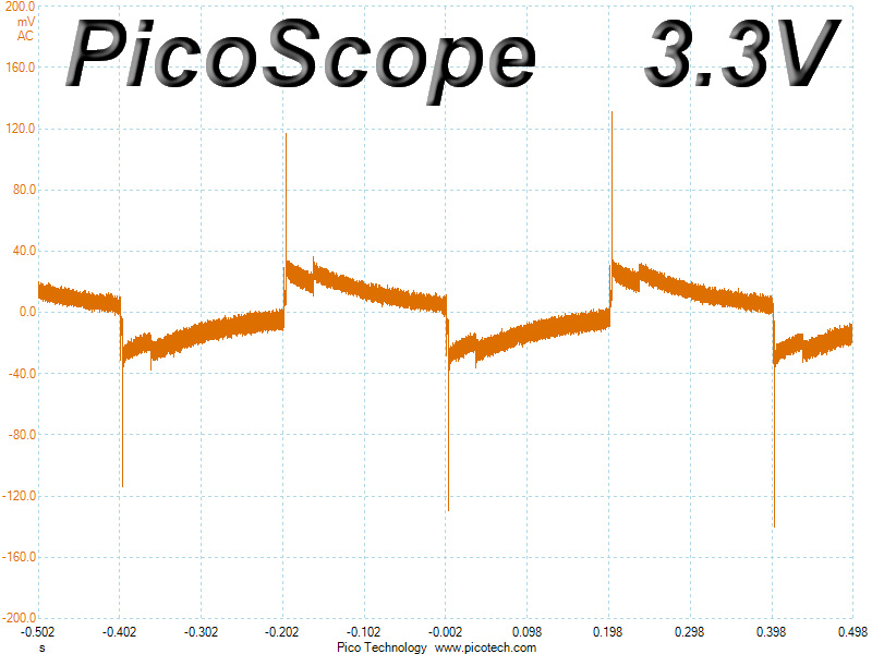
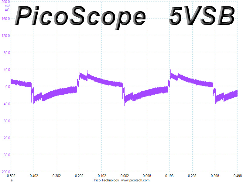
Transient Response at 50% Load
Turn-On Transient Tests
We measure the response of the PSU in simpler scenarios of transient loads—during the power-on phase of the PSU—in the next set of tests. In the first test, we turn the PSU off, dial the maximum current that the 5VSB can output, and then switch on the PSU. In the second test, we dial the maximum load that +12V can handle and start the PSU while the PSU is in standby mode. In the last test, while the PSU is completely switched off (we cut off power or switch off the PSU's on/off switch), we dial the maximum load that the +12V rail can handle before switching the PSU on from the loader and restoring power. The ATX specification states that recorded spikes on all rails should not exceed 10% of their nominal values (e.g., +10% for 12V is 13.2V and 5.5V is 5V).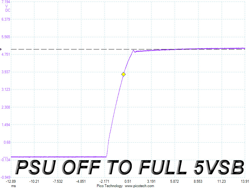
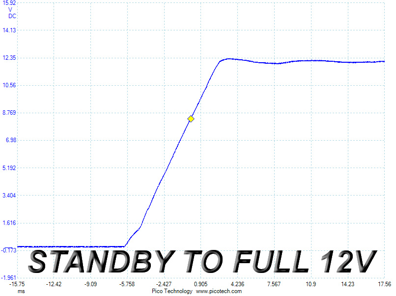
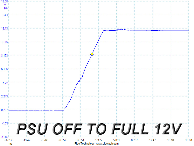
At 5VSB, we measured a very small spike, which is nothing to worry about. We noticed no voltage overshoots on the +12V rail—on both tests. The slope was smooth. However, there is a small spike after the voltage settles down on the "PSU OFF TO FULL 12V" test.
Mar 13th, 2025 04:43 EDT
change timezone
Latest GPU Drivers
New Forum Posts
- What local LLM-s you use? (106)
- Shadow of the Tomb Raider benchmark (543)
- Free Games Thread (4551)
- I'm looking for a good tool to make the 3D scanning of my mini-pc using the photogrammetry and my Kinect 2. (84)
- TPU's Nostalgic Hardware Club (20091)
- Chilled water + Full-cover GPU Blocks? (0)
- The future of RDNA on Desktop. (135)
- Nvidia's GPU market share hits 90% in Q4 2024 (gets closer to full monopoly) (908)
- Missing nvidia control panel after using nvcleanstall with latest drivers (0)
- RX 9070 availability (223)
Popular Reviews
- AMD Ryzen 9 9950X3D Review - Great for Gaming and Productivity
- Sapphire Radeon RX 9070 XT Nitro+ Review - Beating NVIDIA
- XFX Radeon RX 9070 XT Mercury OC Magnetic Air Review
- Dough Spectrum Black 32 Review
- FSP MP7 Black Review
- ASUS Radeon RX 9070 TUF OC Review
- AMD Ryzen 7 9800X3D Review - The Best Gaming Processor
- ASUS GeForce RTX 5090 TUF Review
- NVIDIA GeForce RTX 5070 Founders Edition Review
- MSI MAG B850 Tomahawk Max Wi-Fi Review
Controversial News Posts
- NVIDIA GeForce RTX 50 Cards Spotted with Missing ROPs, NVIDIA Confirms the Issue, Multiple Vendors Affected (513)
- AMD Radeon RX 9070 and 9070 XT Listed On Amazon - One Buyer Snags a Unit (261)
- AMD RDNA 4 and Radeon RX 9070 Series Unveiled: $549 & $599 (260)
- AMD Mentions Sub-$700 Pricing for Radeon RX 9070 GPU Series, Looks Like NV Minus $50 Again (249)
- NVIDIA Investigates GeForce RTX 50 Series "Blackwell" Black Screen and BSOD Issues (244)
- AMD Radeon RX 9070 and 9070 XT Official Performance Metrics Leaked, +42% 4K Performance Over Radeon RX 7900 GRE (195)
- AMD Radeon RX 9070-series Pricing Leaks Courtesy of MicroCenter (158)
- AMD Radeon RX 9070 XT Reportedly Outperforms RTX 5080 Through Undervolting (102)