 36
36
XFX Radeon RX 5700 XT Ultra THICC II Review
Circuit Board Analysis »The Card

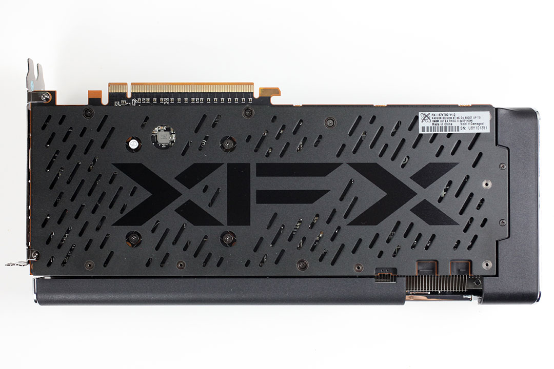

XFX's card looks really good thanks to a modern understated look that mostly uses straight lines and curved edges. The dominant colors are black and gray, with a high-quality metal backplate on the back in matching colors. Dimensions of the card are 29.5 x 13.0 cm.

Installation requires three slots in your system.

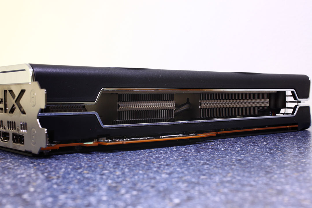
Display connectivity options include three standard DisplayPort 1.4a and an HDMI 2.0b.
AMD took the opportunity to update the display controllers handling these outputs by leveraging DSC 1.2a (display stream compression), which unlocks very high resolution and refresh-rate combinations over a single cable. Among the single-cable display modes supported are 8K 60 Hz (which took two DP 1.3 cables until now), 4K 240 Hz, and 1080p as high as 360 Hz. On top of these, the outputs support HDR and 30 bpc color-depth for better color accuracy in creative applications.

The board uses one 6-pin and one 8-pin power connector. This input configuration is specified for up to 300 watts of power draw.

XFX is including a dual BIOS feature with their card; the default BIOS is called "performance" and the second BIOS is "quiet". I'm not happy with the placement of the BIOS switch as it's impossible to reach with your fingers due to the shroud blocking it—you have to use a pen or similar object to change the switch setting.

AMD's Navi generation of GPUs no longer supports CrossFire. DirectX 12 does include its own set of multi-GPU capabilities, but implementation requires game developers to put serious development time into a feature only a tiny fraction of their customers might ever use.
Disassembly


XFX is using four heatpipes and a copper base on their cooler. This piece of the cooler also provides cooling for the memory chips and VRM circuitry. Note how the memory cooling pad sit on a separate metal place, which leads to higher, but still safe memory temperatures.


Once the main heatsink is removed, an elaborate system of shroud components becomes visible. I think this is the first time I have seen such an approach—it is refreshing and looks great because the cooler "wraps" around the card, giving it a more solid, industrial look and feel.
On the next page, we dive deep into the PCB layout and VRM configuration.
Mar 10th, 2025 12:25 EDT
change timezone
Latest GPU Drivers
New Forum Posts
- RX 9070 availability (158)
- Surface laptop 5 TPL Speed Shift ignored? (1)
- What's your latest tech purchase? (23268)
- newegg ATX 3.1 PSU on Clearance and Free Fan (0)
- Looking for silent 9070 (XT) (9)
- Zen6 is almost here ? (43)
- AMD RX 9070 XT & RX 9070 non-XT thread (OC, undervolt, benchmarks, ...) (1)
- AAF Optimus Modded Driver For Windows 10 & Windows 11 - Only for Realtek HDAUDIO Chips (374)
- Gaming PC instabiliity (10)
- 2022-X58/1366 PIN Motherboards NVME M.2 SSD BIOS MOD Collection (902)
Popular Reviews
- Sapphire Radeon RX 9070 XT Nitro+ Review - Beating NVIDIA
- XFX Radeon RX 9070 XT Mercury OC Magnetic Air Review
- ASUS Radeon RX 9070 TUF OC Review
- MSI MAG B850 Tomahawk Max Wi-Fi Review
- NVIDIA GeForce RTX 5080 Founders Edition Review
- NVIDIA GeForce RTX 5070 Founders Edition Review
- Corsair Vengeance RGB CUDIMM DDR5-8800 48 GB CL42 Review
- AMD Ryzen 7 9800X3D Review - The Best Gaming Processor
- ASUS GeForce RTX 5070 Ti TUF OC Review
- MSI GeForce RTX 5070 Ti Gaming Trio OC+ Review
Controversial News Posts
- NVIDIA GeForce RTX 50 Cards Spotted with Missing ROPs, NVIDIA Confirms the Issue, Multiple Vendors Affected (513)
- AMD Plans Aggressive Price Competition with Radeon RX 9000 Series (277)
- AMD Radeon RX 9070 and 9070 XT Listed On Amazon - One Buyer Snags a Unit (261)
- AMD RDNA 4 and Radeon RX 9070 Series Unveiled: $549 & $599 (260)
- AMD Mentions Sub-$700 Pricing for Radeon RX 9070 GPU Series, Looks Like NV Minus $50 Again (248)
- NVIDIA Investigates GeForce RTX 50 Series "Blackwell" Black Screen and BSOD Issues (244)
- AMD Radeon RX 9070 and 9070 XT Official Performance Metrics Leaked, +42% 4K Performance Over Radeon RX 7900 GRE (195)
- AMD Radeon RX 9070-series Pricing Leaks Courtesy of MicroCenter (158)