 6
6
NZXT HALE82 V2 700 W Review
Voltage Regulation, Hold-up Time & Inrush Current »A Look Inside & Component Analysis
Before reading this page, we strongly suggest a look at this article, which will help you understand the internal components of a PSU much better. Our main tool for the disassembly of the PSU is a Thermaltronics TMT-9000S soldering and rework station. It is of extreme quality and is equipped with a matching de-soldering gun. With such equipment in hand, breaking apart every PSU is like a walk in the park!


This PSU is most likely made by Sirtec and is nothing special in terms of design. The white PCB may look nice but the used components aren't that appealing as the caps that filter the rails in the secondary side are provided by Suscon. Passive components are also used for the rectification of the +12V rail, which leads to higher energy dissipation than on mosfet solutions. The outdated group regulation scheme used in the secondary side will also affect performance with highly unbalanced loads on the rails.
We wonder why NZXT decided to combine a modern external appearance and a fully modular cabling design with such an outdated design. We would highly prefer it if they added several native cables to then offer an independent regulation scheme instead of the lousy group regulation scheme. NZXT obviously invested into appearances instead of boosting performance under certain conditions.
The first part of the transient filter consists of a single X and two Y caps. On the former, a CMD02X is used to block the current through the cap's discharge resistor when AC voltage is connected and automatically discharge the cap through the corresponding resistor when AC is disconnected. This results in less energy dissipation, which increases efficiency. The second part of the transient filter is on the main PCB and includes two CM chokes, one X cap, two Y caps, and an MOV that has been installed behind the bridge rectifier—a weird location for the MOV as it is usually installed before the bridge rectifier to also protect it.

The single bridge rectifier is bolted to a dedicated heatsink. Right in front of it are the MOV and the PFC input capacitor which filters the ripple of the bridge's output before it enters the APFC circuit.
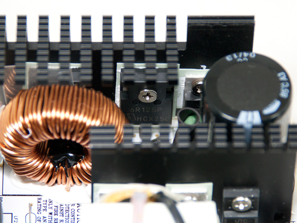

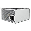
In the APFC, two Infineon IPW60R125CP fets and a CREE C3D08060A boost diode shape the current's waveform to match the voltage one. The hold-up cap is provided by Teapo (400 V, 390 μF, LH series). It is rated at only up to 85°C, and its capacity is rather small for the needs of this PSU, which our hold-up tests will clearly show.
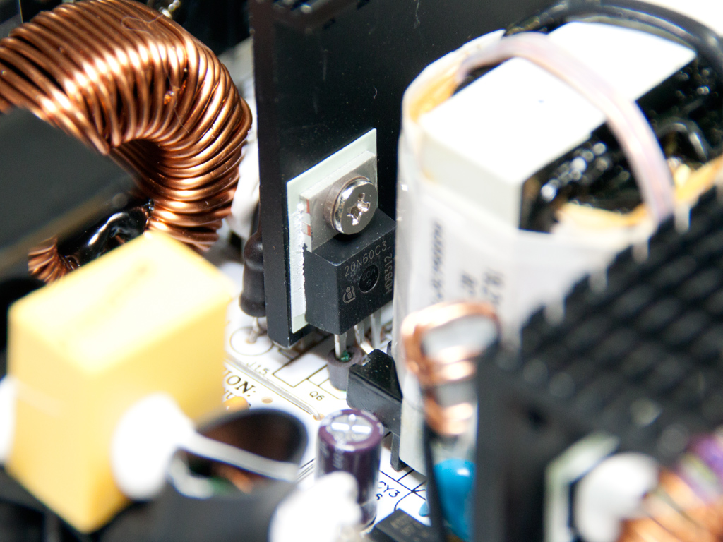

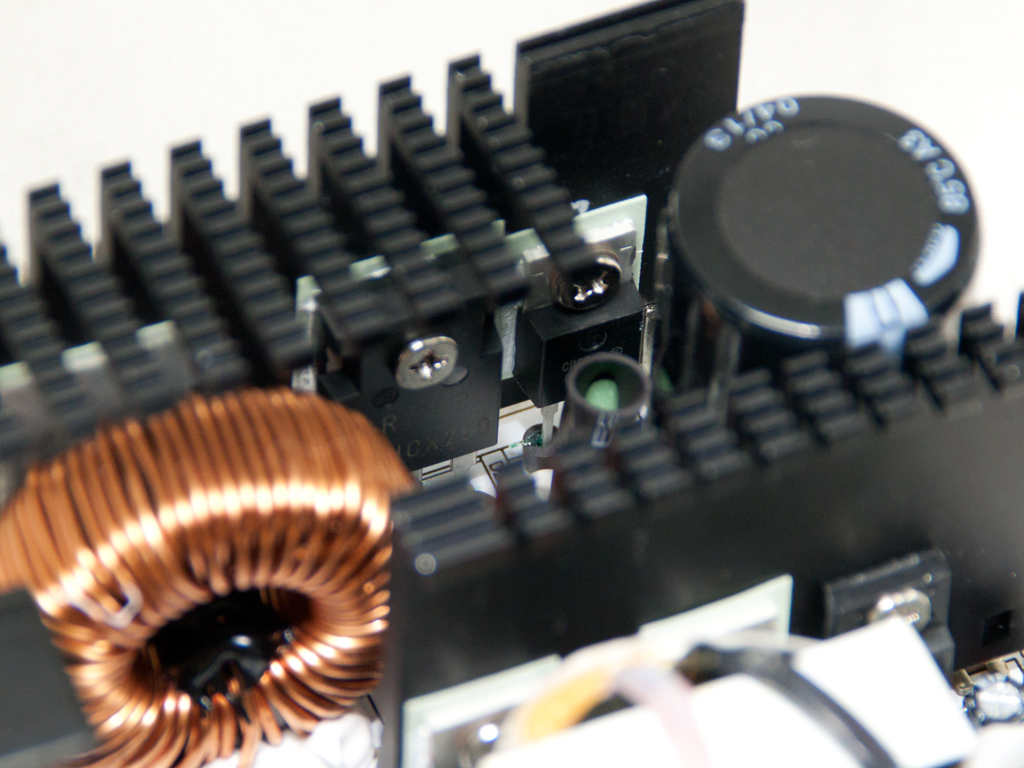
Two Infineon SPP20N60C3 fets are used as main switchers. The same heatsink that holds the above fets also hosts the SBR that rectifies the 5VSB rail, a UTC 2N60L.

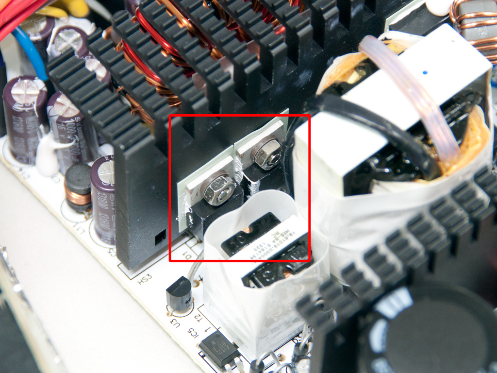


Things don't look so good on the secondary side since we only found two toroidal chokes, a clear indication that a group regulated scheme is used for the generation of the rails. NZXT should know better and avoid such an outdated technique in a modern PSU because it dooms crossload performance and doesn't allow the unit to meet the requirements Intel set for Haswell compatibility. NZXT even used less efficient SBRs (Schottky Barrier Diodes) instead of mosfets to further reduce cost.
The +12V rail is rectified by four PFR40L60CT while the minor rails are handled by three Mospec S30D45C SBRs. To make things even worse, all filtering caps in the secondary are provided by Suscon, a company that isn't among our favorites when it comes to caps.


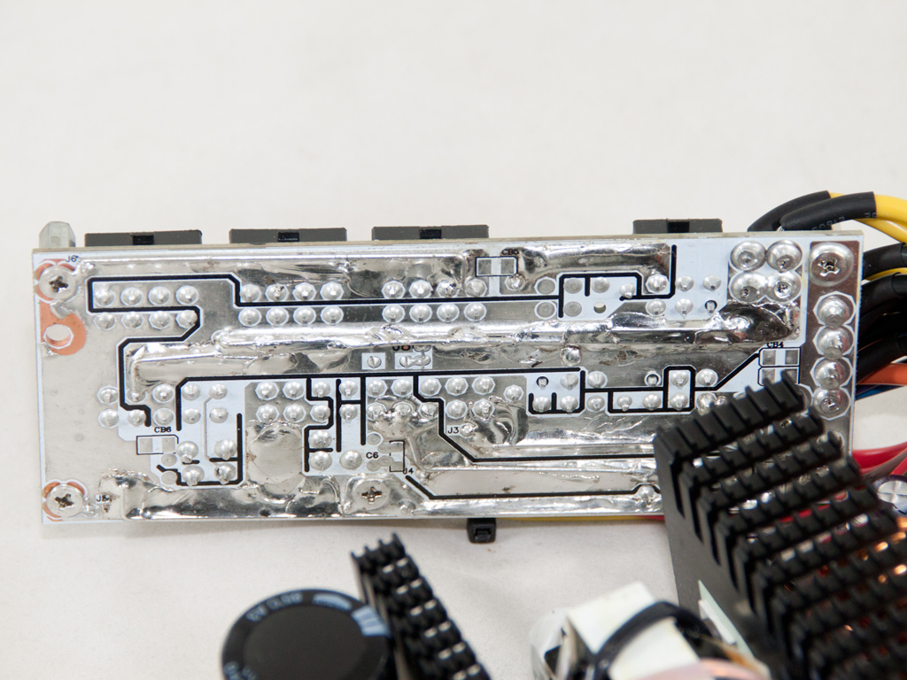
We found a pair of electrolytic caps at the front of the modular PCB. These are for extra ripple filtering, and the soldering job on the rear side is a mess.
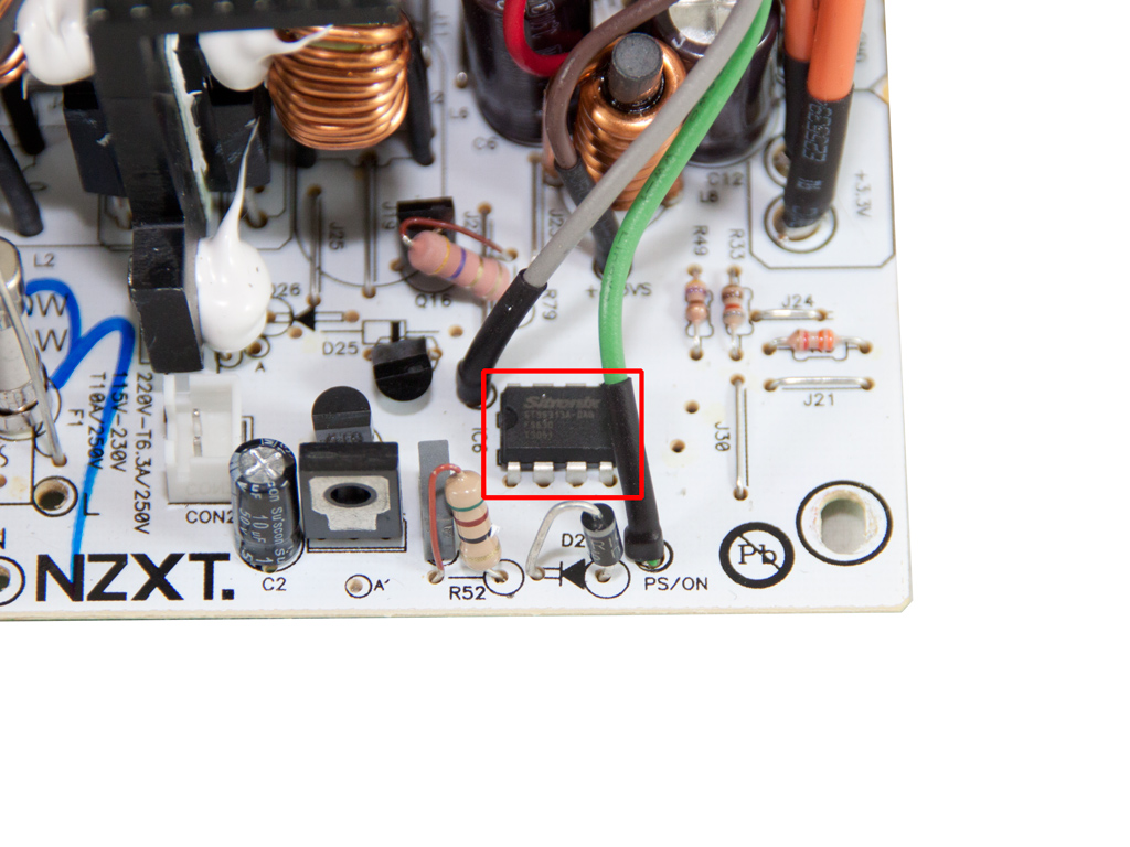
The protection's IC is soldered directly to the main PCB. It is a Sitronix ST95313 IC for which we didn't find any information on the net. Based on its small size and the unit's specifications, it must only provide the very basic protection features.


Soldering quality on the main PCB is of acceptable quality, but we have seen much better soldering jobs in even more affordable units.
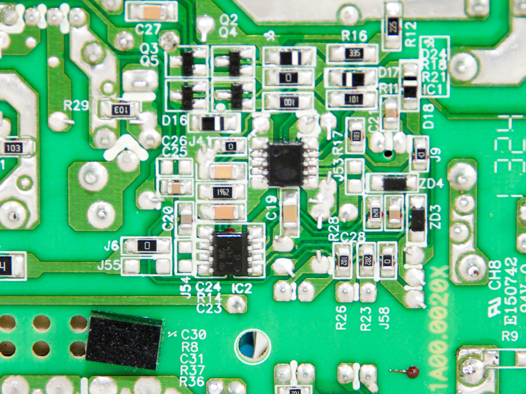
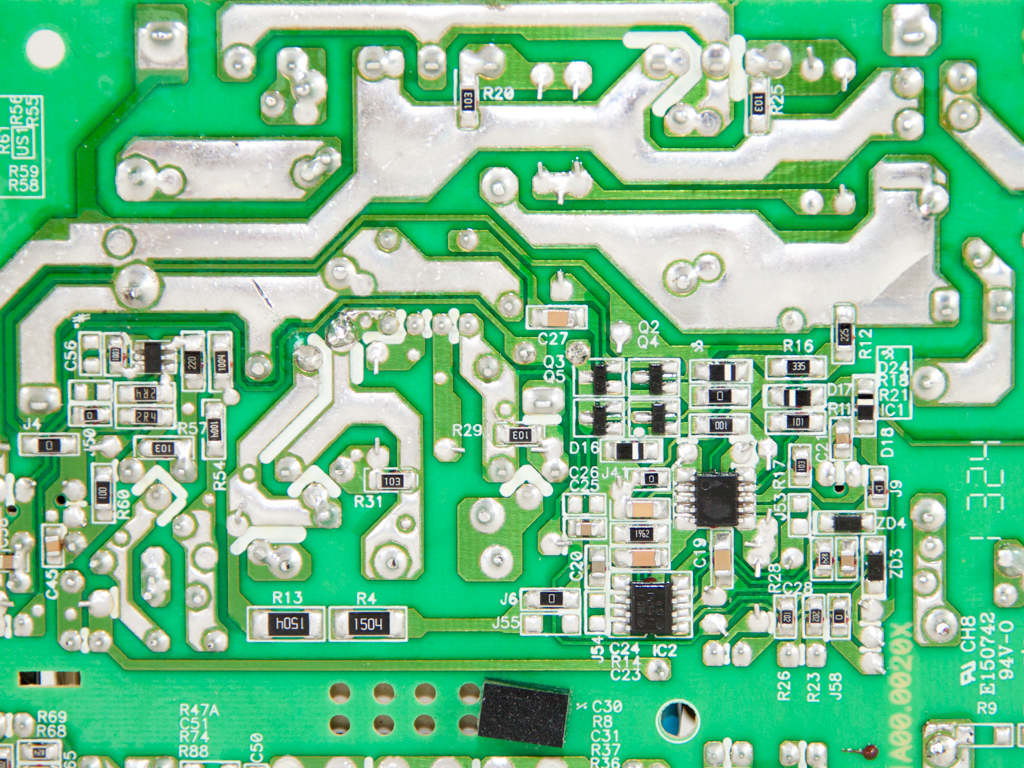
We spotted a CM6803 IC, the combo PFC/Standby controller, on the solder side of the PCB. It is supported by a CM03X Green PFC controller.
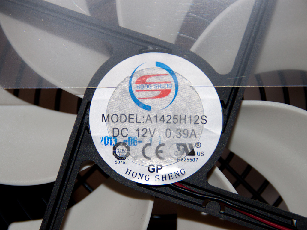
The fan is provided by Hong Sheng, and its model number is A1425H12S (9 - 13.8 V, 0.39 A, 1800 RPM, 97.2 CFM, 36.2 dBA). It has sleeve bearings and is quite strong, which then leads to high output noise.
Mar 4th, 2025 10:19 EST
change timezone
Latest GPU Drivers
New Forum Posts
- WD Black or Gold for Gaming (10TB) (6)
- 2022-X58/1366 PIN Motherboards NVME M.2 SSD BIOS MOD Collection (901)
- AMD Path Tracing Toyshop Demo (9)
- Ram downclocking after restart. (16)
- B550 phantom Gaming ITX/AX bios problem. (7)
- Easy to open wired mice (8)
- Windows 11 General Discussion (5778)
- Microcenter GPU Stock status (17)
- It's happening again, melting 12v high pwr connectors (999)
- DTS DCH Driver for Realtek HDA [DTS:X APO4 + DTS Interactive] (2107)
Popular Reviews
- AMD Radeon RX 9070 Series Technical Deep Dive
- NVIDIA GeForce RTX 5070 Founders Edition Review
- ASUS GeForce RTX 5070 Ti TUF OC Review
- EIZO FlexScan EV4340X Review - A Multitasking Powerhouse
- RAWM ES21M Review
- AMD Ryzen 7 9800X3D Review - The Best Gaming Processor
- be quiet! Pure Base 501 DX Review
- MSI GeForce RTX 5070 Ti Vanguard SOC Review
- MSI GeForce RTX 5070 Ti Ventus 3X OC Review
- ASUS ROG Harpe Ace Mini Review
Controversial News Posts
- NVIDIA GeForce RTX 50 Cards Spotted with Missing ROPs, NVIDIA Confirms the Issue, Multiple Vendors Affected (513)
- AMD Plans Aggressive Price Competition with Radeon RX 9000 Series (277)
- AMD Radeon RX 9070 and 9070 XT Listed On Amazon - One Buyer Snags a Unit (260)
- AMD Mentions Sub-$700 Pricing for Radeon RX 9070 GPU Series, Looks Like NV Minus $50 Again (248)
- NVIDIA Investigates GeForce RTX 50 Series "Blackwell" Black Screen and BSOD Issues (244)
- AMD RDNA 4 and Radeon RX 9070 Series Unveiled: $549 & $599 (234)
- AMD Radeon RX 9070 and 9070 XT Official Performance Metrics Leaked, +42% 4K Performance Over Radeon RX 7900 GRE (195)
- AMD Radeon RX 9070-series Pricing Leaks Courtesy of MicroCenter (158)