ECS nForce4-A939 Voltmods |
|
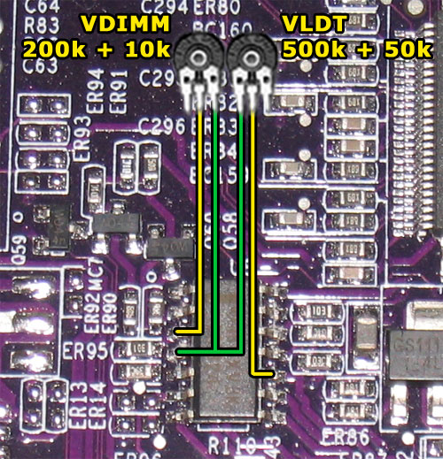
VDIMM & VLDT
Datasheet of the LM324 controller:http://www-s.ti.com/sc/ds/lm324.pdf
This controller is responsible for Vdimm as well as VLDT.

VDIMM (left side of the LM324 according to the picture)
Connect the 200K and the 10K potentiometers in series, thus getting a total resistance of 210K. You could also only use the single 200K poti, but I like to have a bit more precision using the additional 10K poti to adjust the voltage when the changes are too high using the 200K poti alone (mostly in the lower K-Ohm-range). Finally just make the connection between pin#3 and pin#4(VCC) like shown in the picture.VDimm and VTT Measure

For the VLDT-mod you do basically the same as for VDimm. You connect 1x 500K and 1x 50K potentiometers in series, and then solder them in between pin#10 and pin#4(VCC). That's all. Just like shown in the picture above.
Important info concerning VLDT:
VLDT is directly dependant on VChipset! That means VLDT can never exceed VChipset. For example for a VLDT of 1.5V you would need to set VChipset to at least 1.55V. And so on...
The higher you set VChipset, the higher the range of adjustable VLDT voltages.
VLDT Measure
Please have a look at the next page. The picture which shows the VChipset measuring points, also shows the measuring points for VLDT as they are located directly next to eachother.
Feb 22nd, 2025 07:25 EST
change timezone
Latest GPU Drivers
New Forum Posts
- Nvidia's GPU market share hits 90% in Q4 2024 (gets closer to full monopoly) (478)
- Solidigm NVMe Custom Modded Driver for All NVMe Brands SSDs & Any NVMe SSDs (203)
- can you use 2 of the same model "centers" as 2.0 ? (1)
- Warning about DOCP (12)
- Is this thermal paste or phase change pad? (4)
- Windows 11 General Discussion (5688)
- It's happening again, melting 12v high pwr connectors (858)
- Bizarre issue (0)
- PC Turns Off Immediately After Pressing Power Button--Must be Held Down to Power On (2)
- Where did the 7900xtx go? (20)
Popular Reviews
- MSI GeForce RTX 5070 Ti Ventus 3X OC Review
- Gigabyte GeForce RTX 5090 Gaming OC Review
- Galax GeForce RTX 5070 Ti 1-Click OC White Review
- ASUS GeForce RTX 5070 Ti TUF OC Review
- Ducky One X Inductive Keyboard Review
- MSI GeForce RTX 5070 Ti Vanguard SOC Review
- MSI GeForce RTX 5070 Ti Gaming Trio OC+ Review
- darkFlash DY470 Review
- MSI MAG Z890 Tomahawk Wi-Fi Review
- Palit GeForce RTX 5070 Ti GameRock OC Review
Controversial News Posts
- NVIDIA GeForce RTX 5090 Spotted with Missing ROPs, NVIDIA Confirms the Issue, Multiple Vendors Affected, RTX 5070 Ti, Too (303)
- AMD Radeon 9070 XT Rumored to Outpace RTX 5070 Ti by Almost 15% (302)
- AMD Plans Aggressive Price Competition with Radeon RX 9000 Series (269)
- AMD is Taking Time with Radeon RX 9000 to Optimize Software and FSR 4 (256)
- AMD Radeon RX 9070 and 9070 XT Listed On Amazon - One Buyer Snags a Unit (247)
- Edward Snowden Lashes Out at NVIDIA Over GeForce RTX 50 Pricing And Value (241)
- AMD Denies Radeon RX 9070 XT $899 USD Starting Price Point Rumors (239)
- New Leak Reveals NVIDIA RTX 5080 Is Slower Than RTX 4090 (215)