A Detailed Look Into PSUs |
|
Switching Regulator Topologies used in Contemporary PSUs


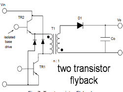
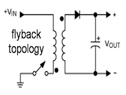
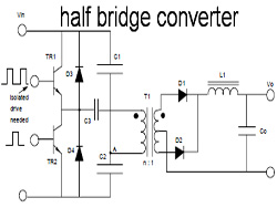
According to the peak current that will pass from the main switches, the desired efficiency levels, the maximum operating voltage across the switches the cost etc. a manufacturer has several switching regulator topologies at his disposal.
Below you will find a table that compares several switching regulator topologies (Marty Brown: Power Supply Cookbook)
| Topology | Power Range | Vin (DC) Range | Primary/Secondary Isolation | Typical Efficiency | Relative Cost |
|---|---|---|---|---|---|
| Buck | 0-1000 W | 5-40 V | No | 78% | 1.0 |
| Boost | 0-150 W | 4-40 V | No | 80% | 1.0 |
| Buck-Boost | 0-150 W | 5-40 V | No | 80% | 1.0 |
| Flyback | 0-150 W | 5-500 V | Yes | 80% | 1.2 |
| Resonant Forward | 0-60 W | 60-400 V | Yes | 87% | 1.2 |
| 1T forward | 0-150 W | 5-500 V | Yes | 78% | 1.4 |
| Push-Pull | 100-1000 W | 50-1000 V | Yes | 75% | 2.0 |
| Half-bridge | 100-500 W | 50-1000 V | Yes | 75% | 2.2 |
| Full-bridge | 400-2000+ W | 50-1000 V | Yes | 73% | 2.5 |
| Quasi Resonant | 100-1000+ W | 50-1000 V | Yes | 87-92% | 2.8 |
Finally, here you will find a very informative pdf file that describes many commonly used topologies.
Apr 8th, 2025 12:36 EDT
change timezone
Latest GPU Drivers
New Forum Posts
- ## [Golden Sample] RTX 5080 – 3300 MHz @ 1.020 V (Stock Curve) – Ultra-Stable & Efficient (26)
- 9070XT or 7900XT or 7900XTX (138)
- ThrottleStop - 14900HX, 4090RTX MSI laptop (0)
- (Anti) SFF fun house (362)
- Windows 11 General Discussion (5942)
- What Happened to the Capacitors in 2002? (7)
- Help me pick a UPS (93)
- There is no GOP ( Graphics Output protocol) support detected in this graphics card. Sapphire Nitro+ RX 580 8GB (5)
- The Official Thermal Interface Material thread (1687)
- Using V/F point only instead of combining it with offset voltage? (7)
Popular Reviews
- The Last Of Us Part 2 Performance Benchmark Review - 30 GPUs Compared
- UPERFECT UStation Delta Max Review - Two Screens In One
- PowerColor Radeon RX 9070 Hellhound Review
- MCHOSE L7 Pro Review
- ASUS Prime X870-P Wi-Fi Review
- Upcoming Hardware Launches 2025 (Updated Apr 2025)
- Sapphire Radeon RX 9070 XT Pulse Review
- Sapphire Radeon RX 9070 XT Nitro+ Review - Beating NVIDIA
- Corsair RM750x Shift 750 W Review
- DDR5 CUDIMM Explained & Benched - The New Memory Standard
Controversial News Posts
- NVIDIA GeForce RTX 5060 Ti 16 GB SKU Likely Launching at $499, According to Supply Chain Leak (161)
- MSI Doesn't Plan Radeon RX 9000 Series GPUs, Skips AMD RDNA 4 Generation Entirely (146)
- Microsoft Introduces Copilot for Gaming (124)
- AMD Radeon RX 9070 XT Reportedly Outperforms RTX 5080 Through Undervolting (119)
- NVIDIA Reportedly Prepares GeForce RTX 5060 and RTX 5060 Ti Unveil Tomorrow (115)
- Over 200,000 Sold Radeon RX 9070 and RX 9070 XT GPUs? AMD Says No Number was Given (100)
- Nintendo Switch 2 Launches June 5 at $449.99 with New Hardware and Games (97)
- NVIDIA GeForce RTX 5050, RTX 5060, and RTX 5060 Ti Specifications Leak (97)