 9
9
Aerocool Project 7 PSU 650 W Review
Load Regulation, Hold-up Time & Inrush Current »A Look Inside & Component Analysis
Before reading this page, we strongly suggest a look at this article, which will help you understand the internal components of a PSU much better. Our main tool for the disassembly of the PSU is a Thermaltronics TMT-9000S soldering and rework station. It is of extreme quality and is equipped with a matching de-soldering gun. For the identification of tiny parts, we use an Andonstar HDMI Digital Microscope.| Aerocool ACP-650FP7 Parts Description | |
|---|---|
| General Data | |
| Manufacturer (OEM) | Andyson |
| Platform Model | - |
| Primary Side | |
| Transient Filter | 2x Y caps, 3x X caps, 2x CM chokes, 1x MOV |
| Bridge Rectifier(s) | 2x GBU1006 (600V, 10A @ 100°C) |
| Inrush Current Protection | NTC Thermistor & Relay |
| APFC Mosfets | 2x Infineon IPP50R140CP (550V, 15A @ 100°C, 0.14 Ohm) |
| APFC Boost Diode | 1x CREE C3D10060A (600V, 14A @ 135°C) |
| Hold-up Cap(s) | 2x Nichicon (420V, 330uF each or 660uF combined, 2000h @ 105°C, GG) |
| Main Switchers | 2x Infineon IPP50R190CE (550V, 15.7A @ 100°C, 0.19 Ohm) Driver IC: Silicon Labs Si8230BD |
| APFC Controller | Champion CM6502S |
| Switching Controller | Champion CM6901 |
| Topology | Primary side: Half-Bridge & LLC Resonant Converter Secondary side: Synchronous Rectification & DC-DC converters |
| Secondary Side | |
| +12V | 8x Infineon BSC014N04LS (40V, 100A @ 100°C, 1.4 mOhm) |
| 5V & 3.3V | DC-DC Converters: 2x CSD86350Q5D power blocks PWM Controller: 2x Anpec APW7073 |
| Filtering Capacitors | Electrolytics: Nippon Chemi-Con (105°C, 7xKY, 7x KZE), 7x Nichicon (105°C) Polymers: 6x Nippon Chemi-Con, 7x FPCAP |
| Supervisor IC | SITI PS223 (OVP, UVP, OCP, SCP, OTP ) |
| Fan Model | 140 mm LED fan (12 V, 0.24 A, 1623 RPM, FDB) |
| 5VSB Circuit | |
| Rectifying Diode | PFR10V45CT (45V, 5x 2A, 0.4V @ 125°C) |
| Standby PWM Controller | Sanken STR-A6069H |
| -12V Circuit | |
| Rectifying Diode | KODENSHI AUK SN7912PI (-12V, 2.2A @ 25°C) |
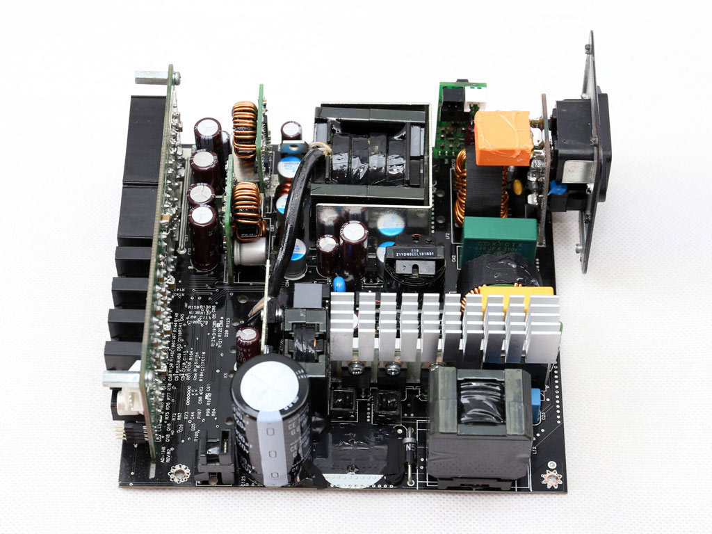
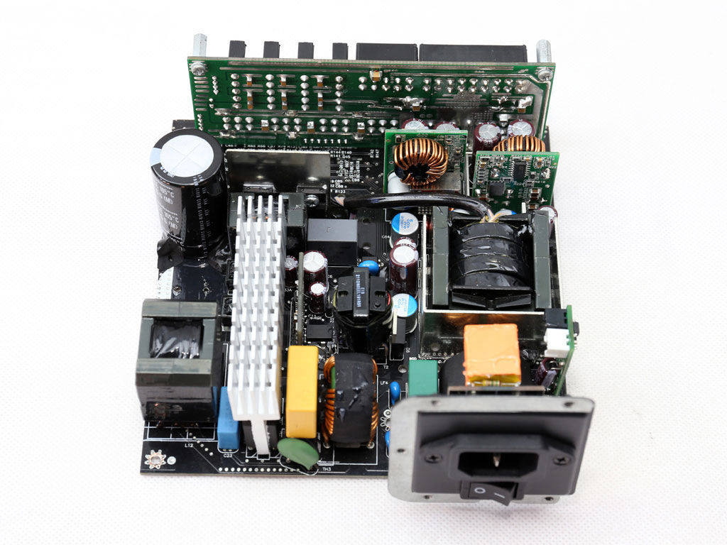
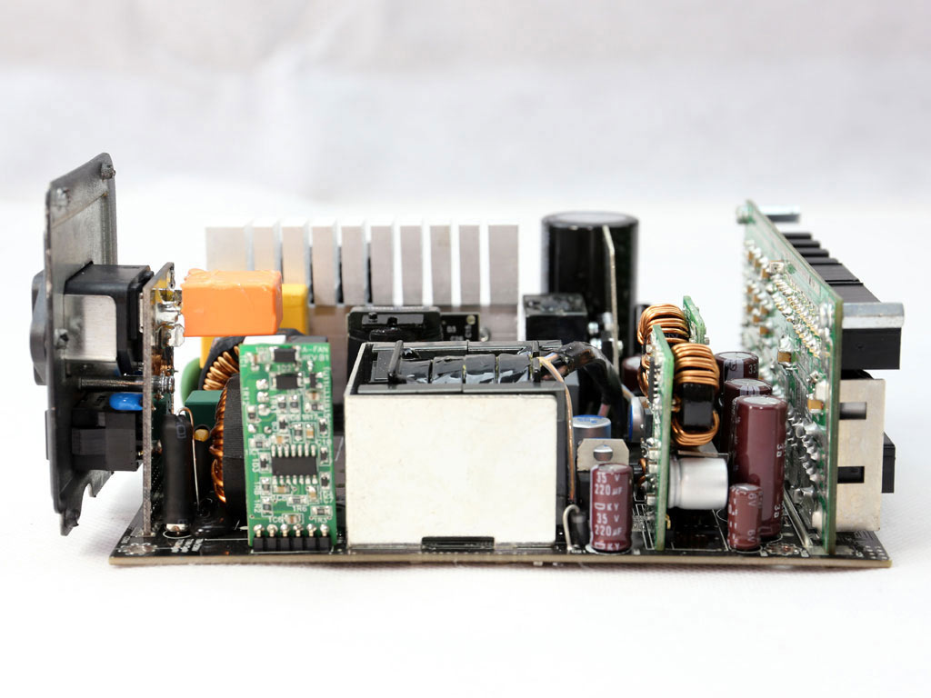
This is Andyson's Titanium platform, which has been downgraded a bit in terms of efficiency since it would have been pretty hard to keep the same efficiency levels without giving up the fully modular cable design or the top-notch ripple suppression and tight load regulation. Over temperature protection along with other modifications (different FETs, caps, etc.) have also been included for the best-possible performance in this wattage range and price category. On the primary side are a half-bridge topology and an LLC resonant converter; the secondary side uses a synchronous design with a pair of DC-DC converters for the generation of the minor rails.
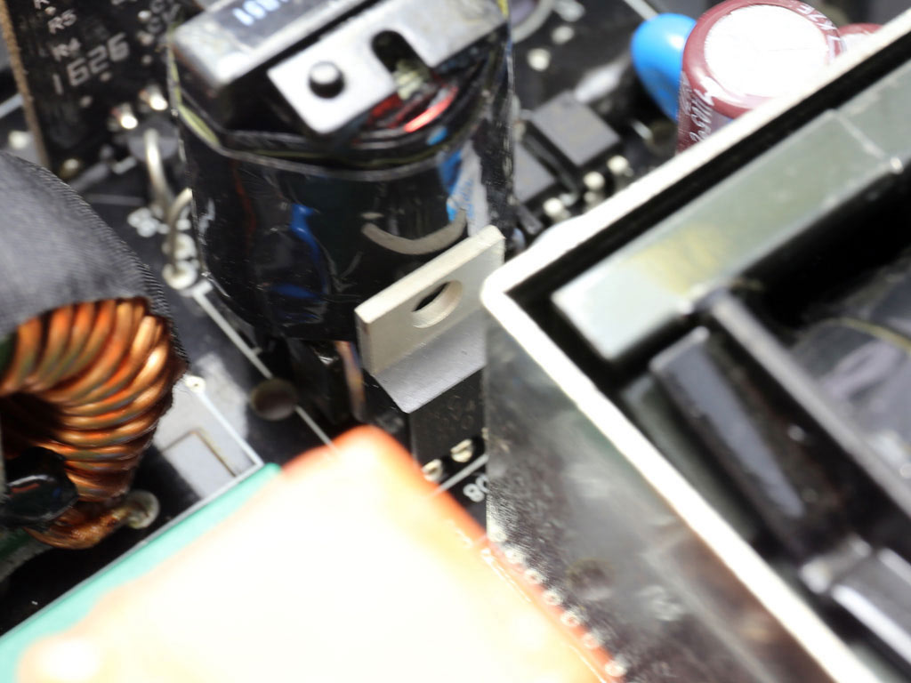
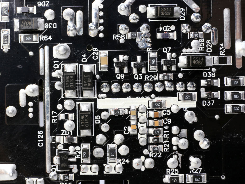
The main transformer uses a special design which restricts its footprint. It is also covered by a metallic shield on three sides.
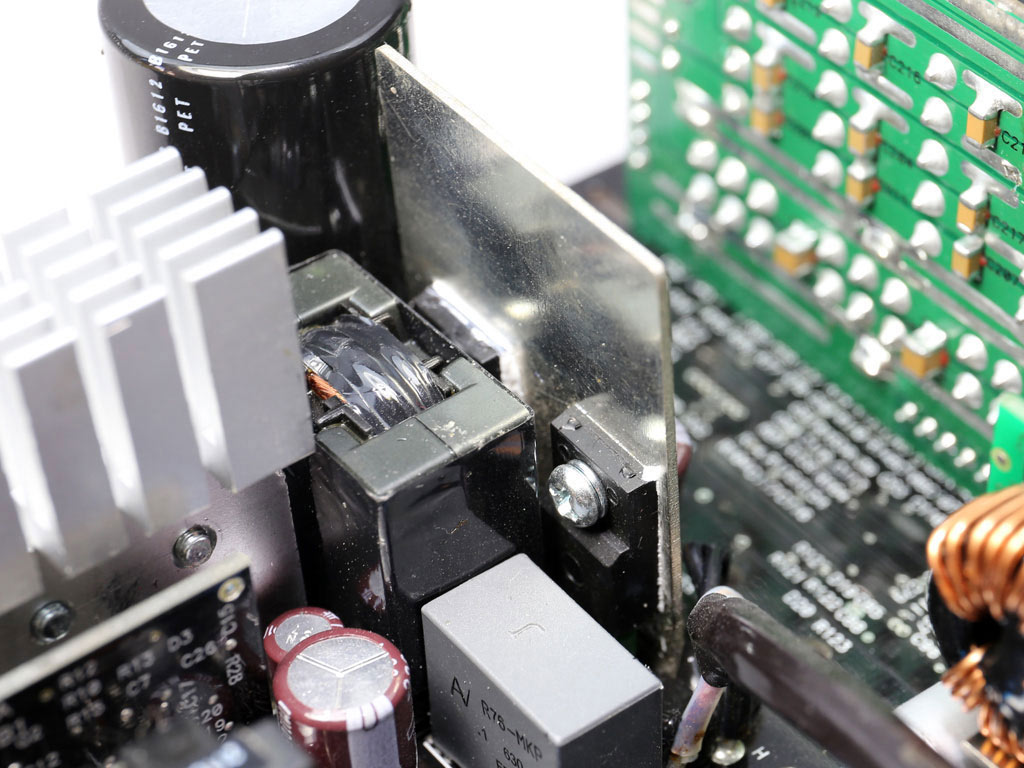
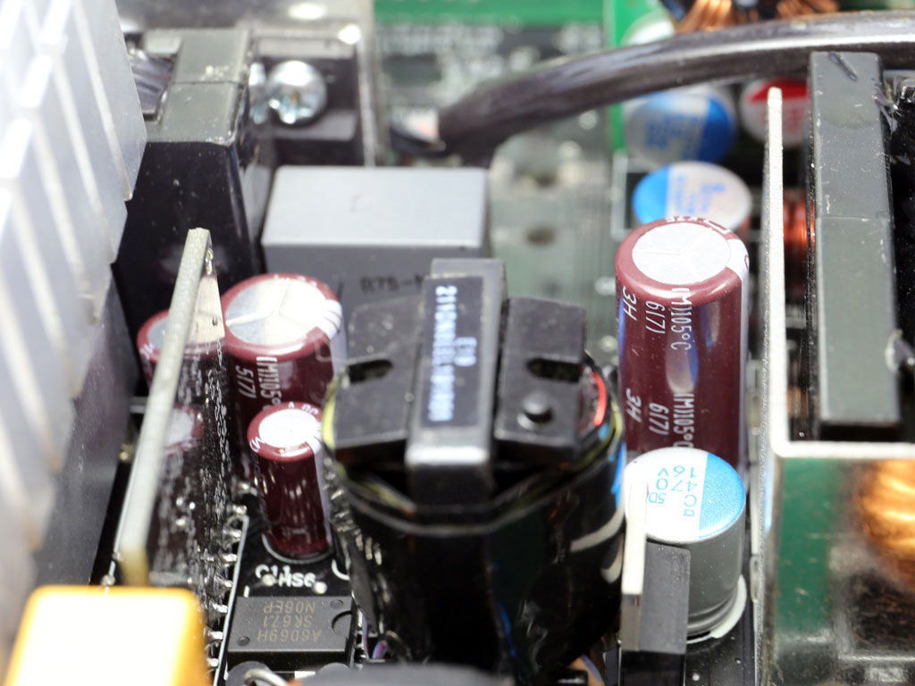
The first part of the EMI filtering stage is on the PCB that holds the AC receptacle. It includes an X and two Y caps. The same filter continues on the main PCB with two more Y caps, two X caps, a pair of CM chokes, and an MOV. There is also an NTC thermistor for protection against large inrush currents. A bypass relay helps the thermistor cool down faster and also offers a small efficiency boost.
Two bridge rectifiers (GBU1006) are used. They are strong enough to meet the needs of the ACP-650FP7.
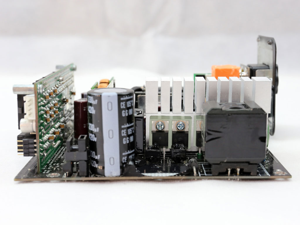
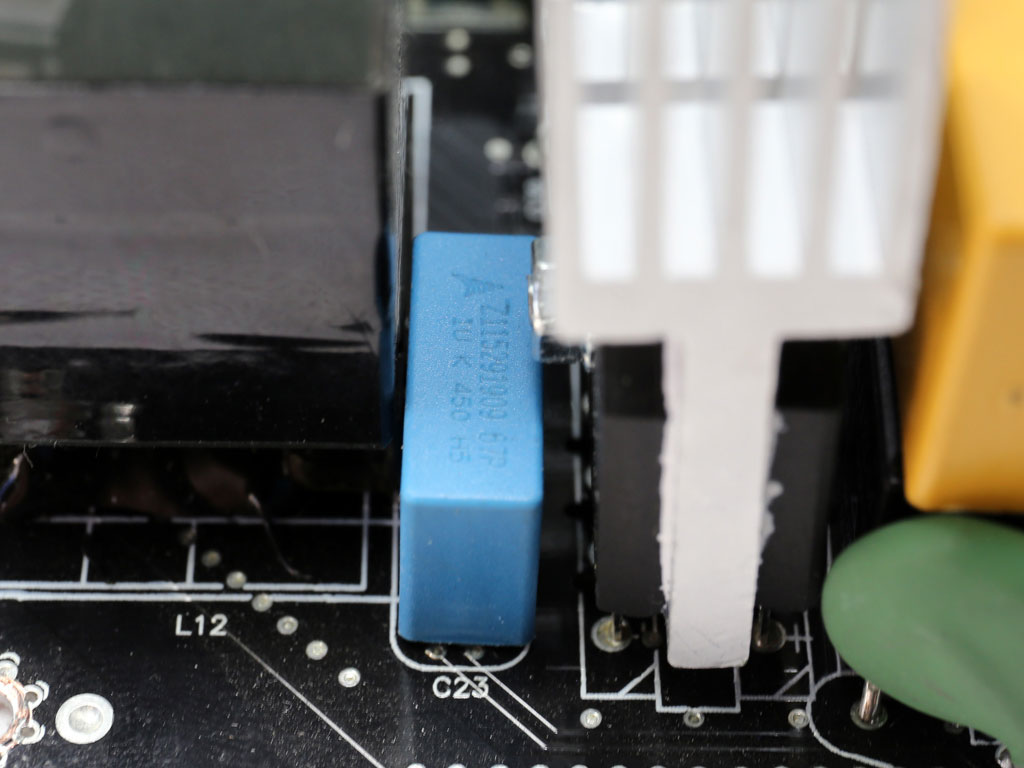
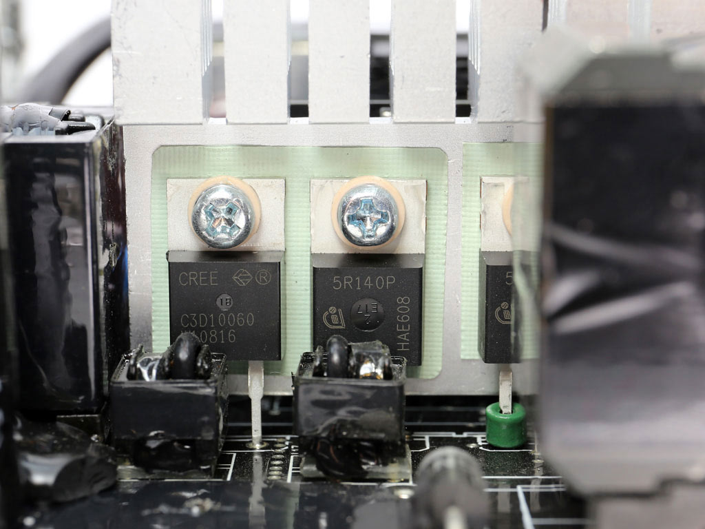
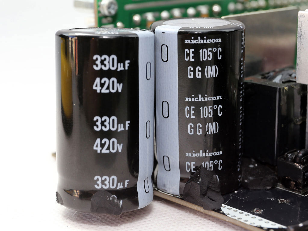
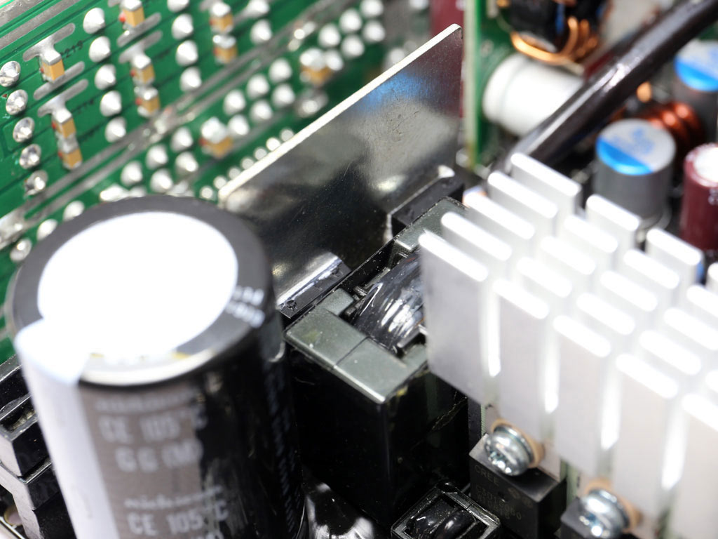
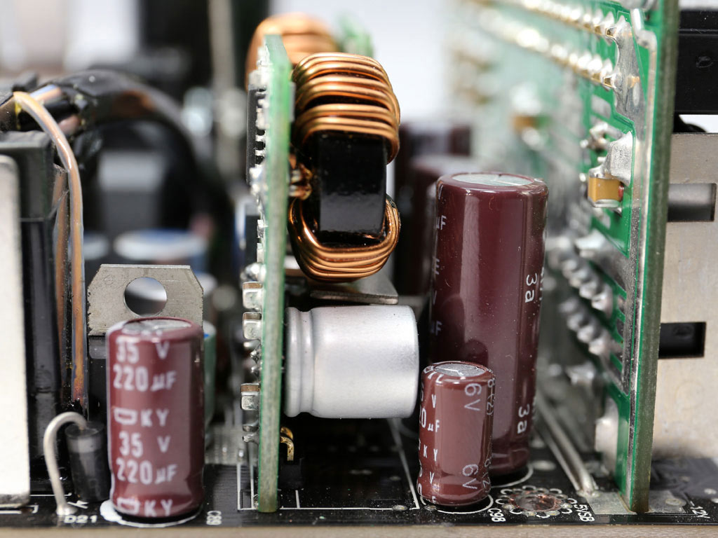
The APFC converter utilizes two Infineon IPP50R140CP FETs and a single CREE C3D10060A boost diode. The two bulk caps are by Nichicon (420V, 330uF each or 660uF combined, 2000h @ 105°C, GG), and their capacity is adequate for the needs of this unit. Here, we insisted on large enough bulk caps capable of delivering a hold-up time below 17 ms and an accurate power ok signal.
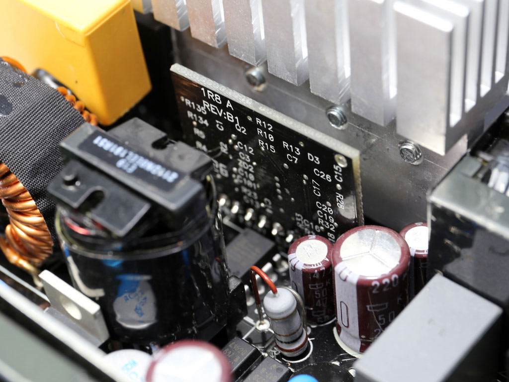
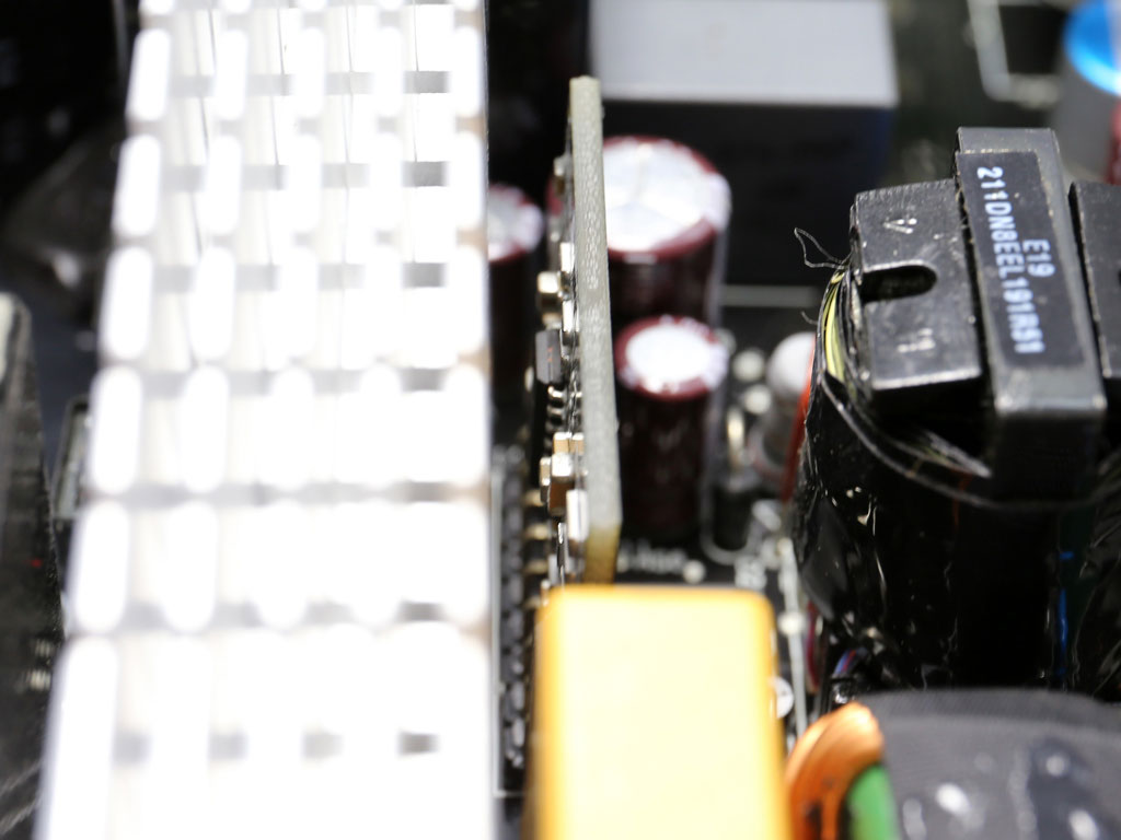
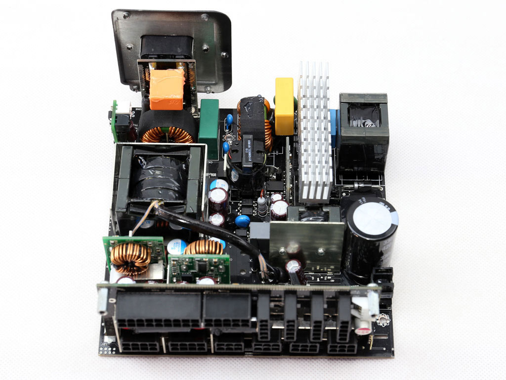
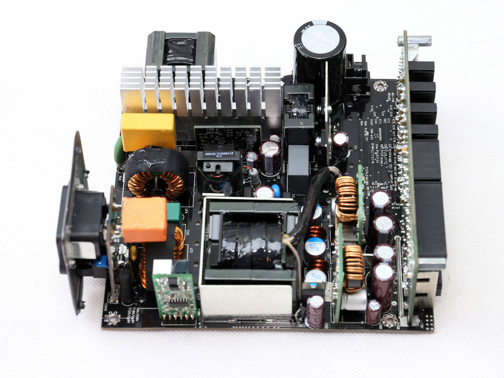
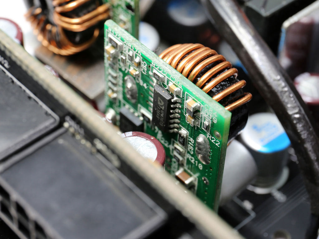
The PFC controller is a Champion CM6502S, and it has been installed on a small vertical daughterboard right next to the primary heatsink.
The primary switching FETs, two Infineon IPP50R190CEs, are configured in a half-bridge topology. An LLC resonant converter is also used for increased efficiency.
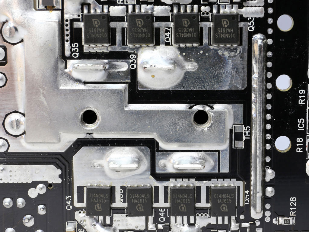
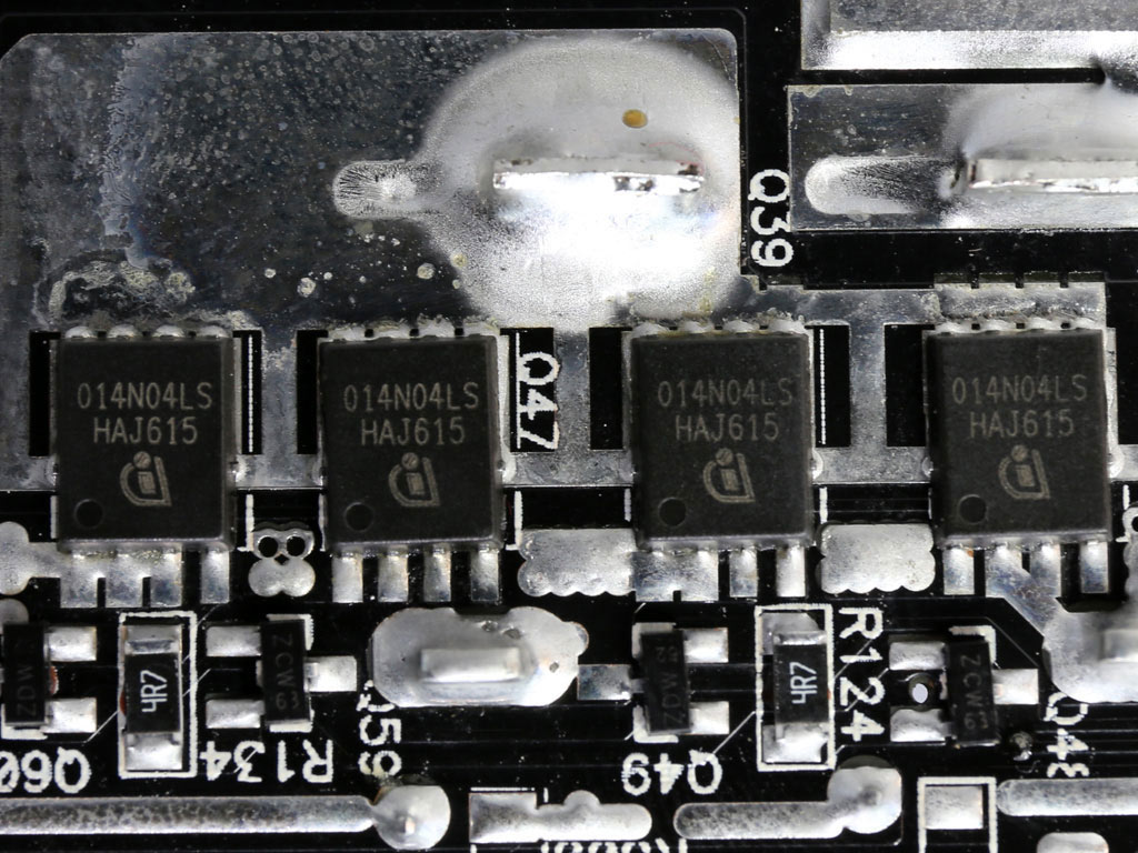
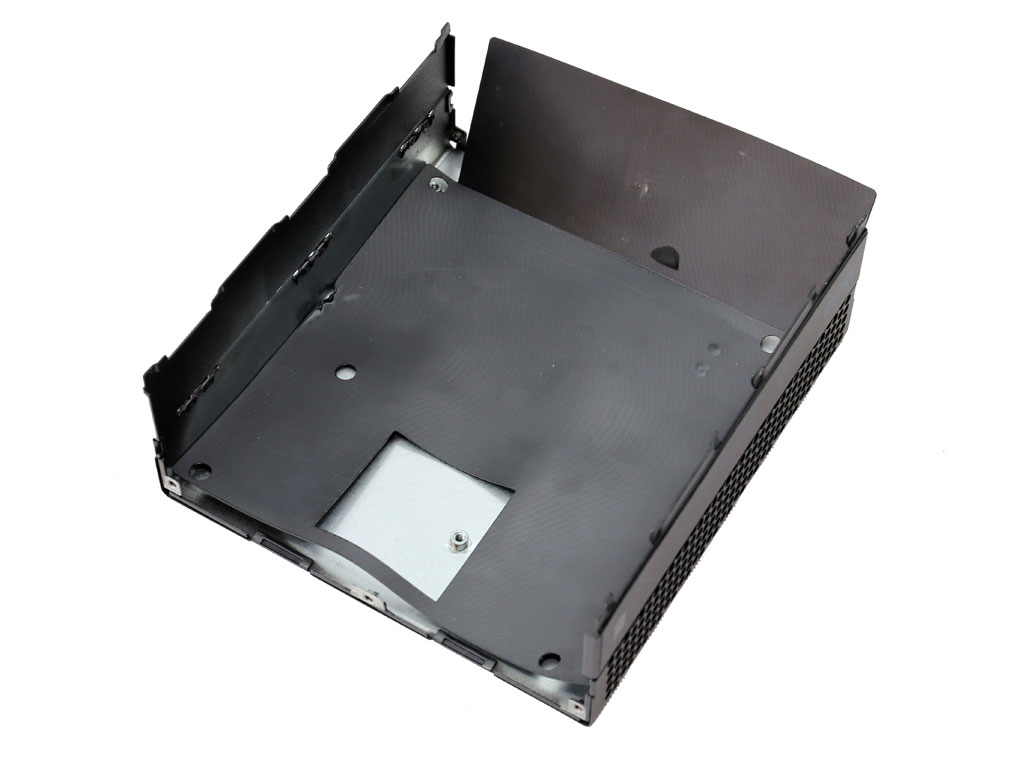
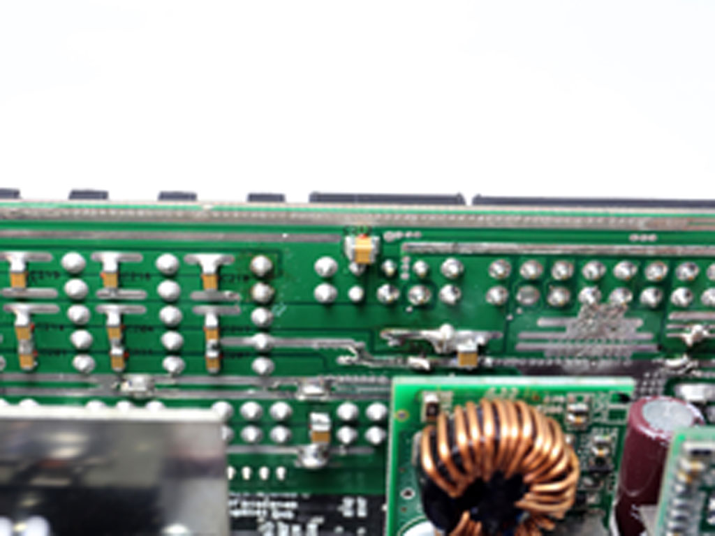
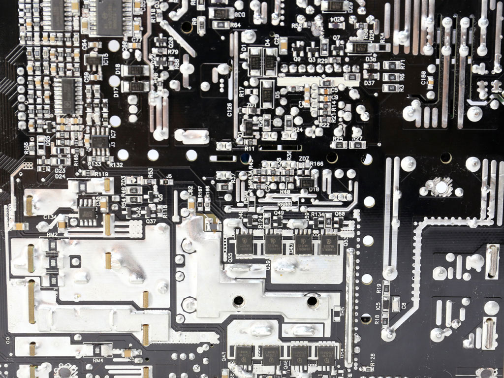
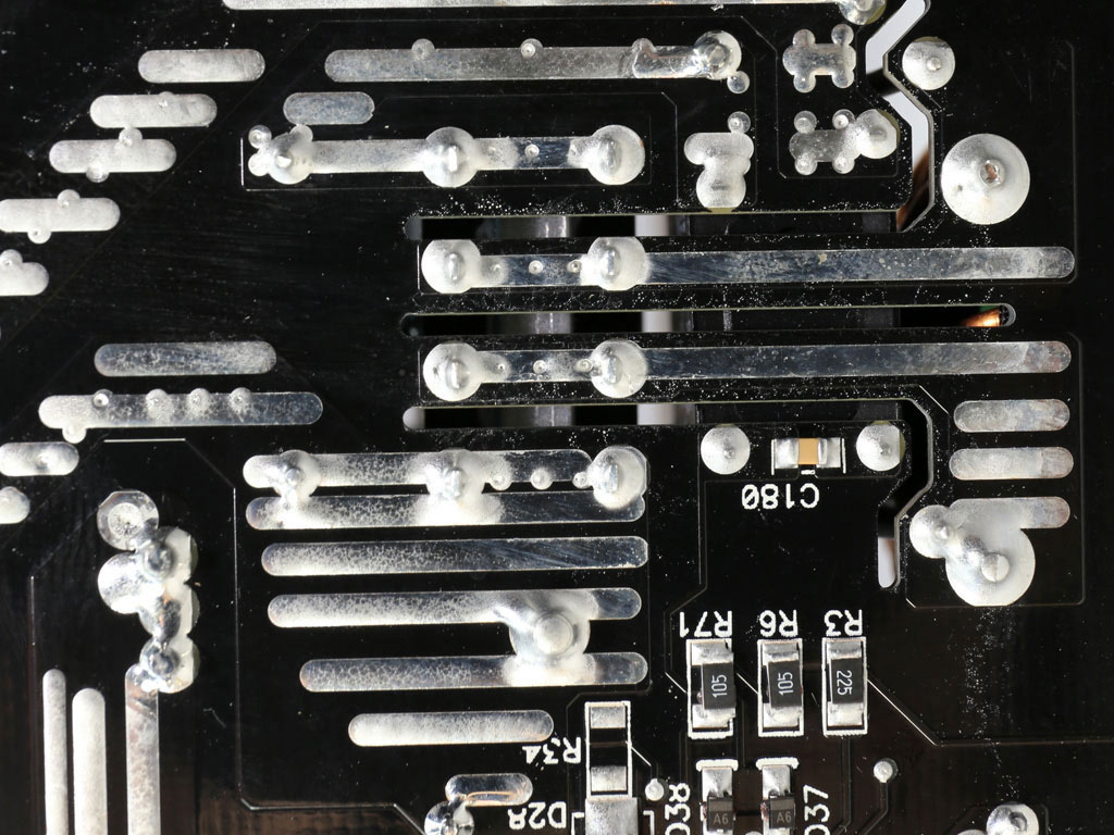
Eight Infineon BSC014N04LS FETs regulate the +12V rail. These FETs are installed to the solder side of the main PCB and are cooled by the chassis. There is a thermal pad (nost shown in the photos above) to allow for the chassis to connect with the +12V FETs.
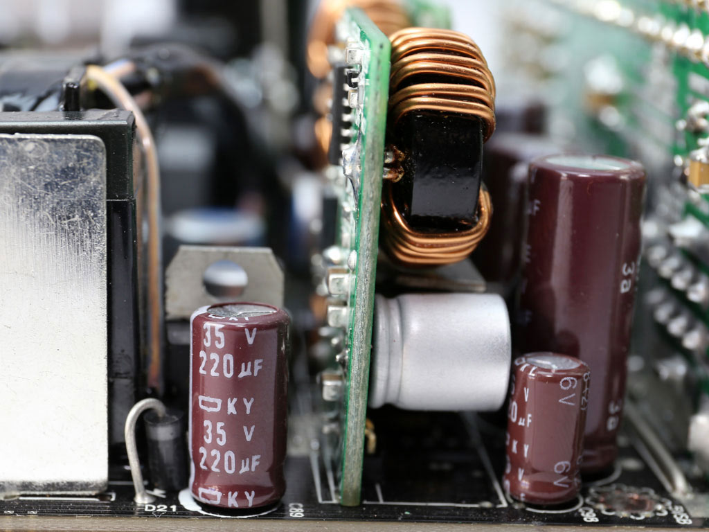
Both electrolytic and polymer caps are used for the filtering of the rails. Nippon Chemi-Con (KZE, KY) and Nichicon provide the electrolytic caps, and the polymers are by Chemi-Con and FPCAP.
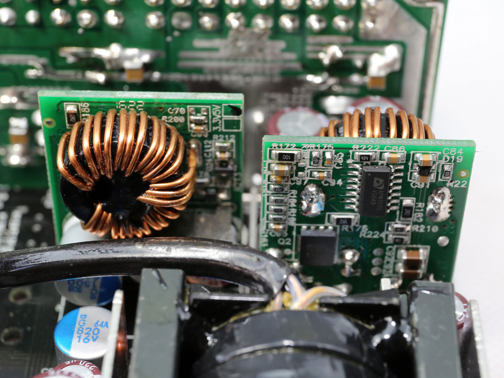
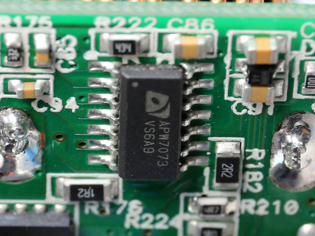
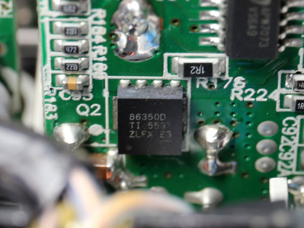
The VRMs that generate the minor rails use two CSD86350Q5D power blocks, and there are two PWM controllers (Anpec APW7073) for those circuits.
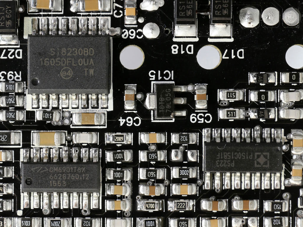
The LLC resonant controller is a Champion CM6901, and it has been installed to the solder side of the main PCB. Next to it, we find the supervisor IC, a SITI PS223, and the driver IC of the primary FETs.
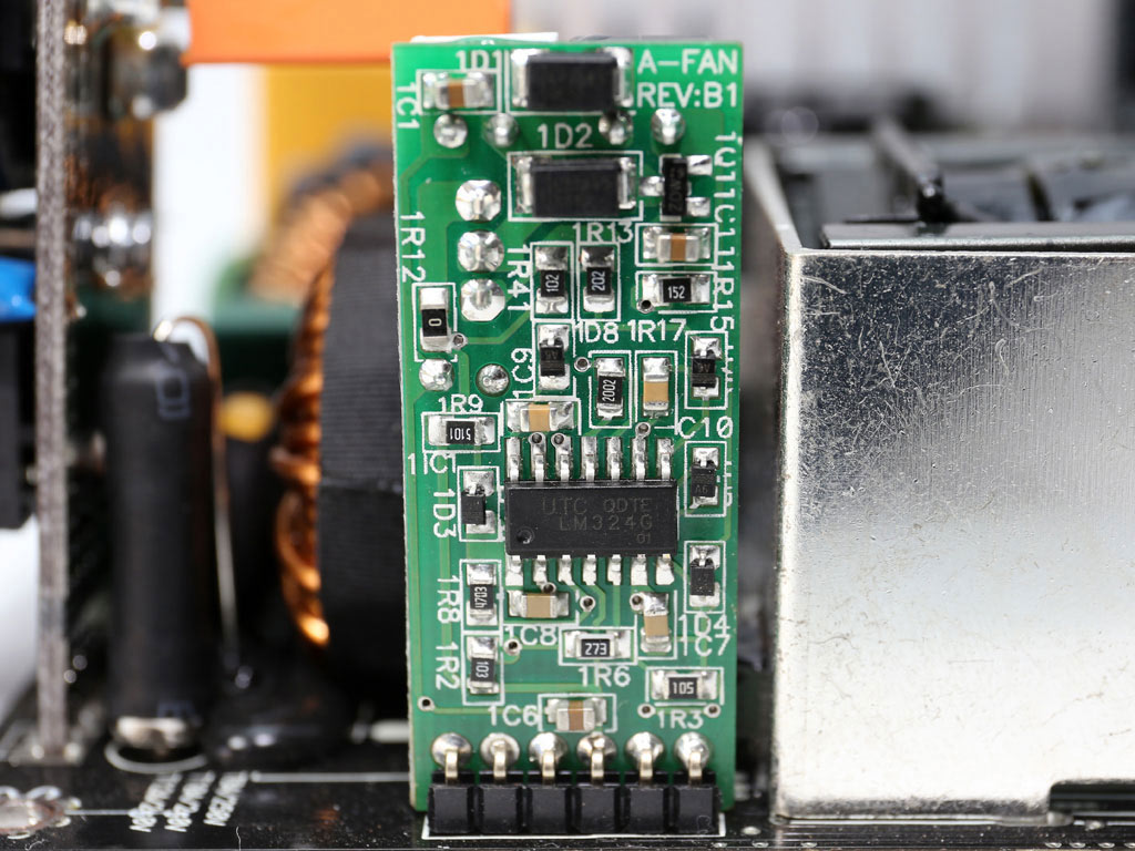
The fan controller uses a Unisonic LM324G IC.
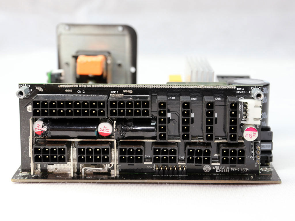
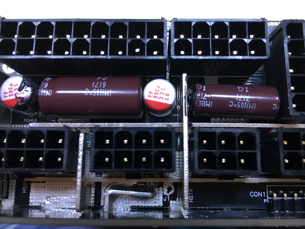
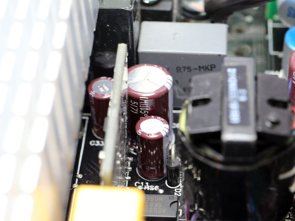
Two Chemi-Con electrolytic caps and a number of polymer FPCAPs on the modular board's primary side provide an extra ripple-filtering layer.
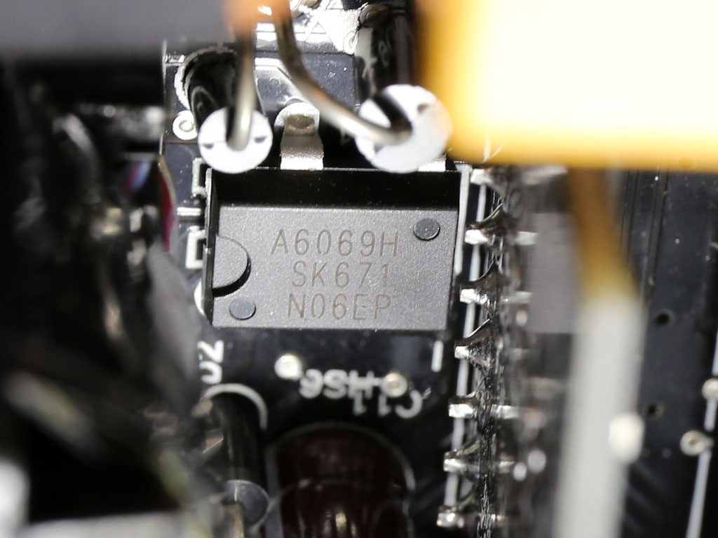
The 5VSB rail is regulated by a PFR10V45CT diode, while its PWM controller is a Sanken STR-A6069H IC.
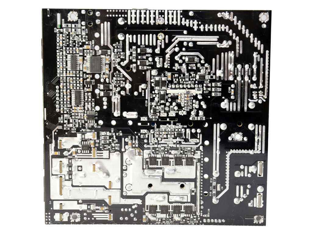
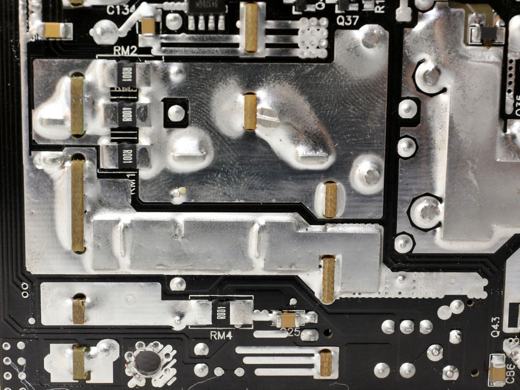
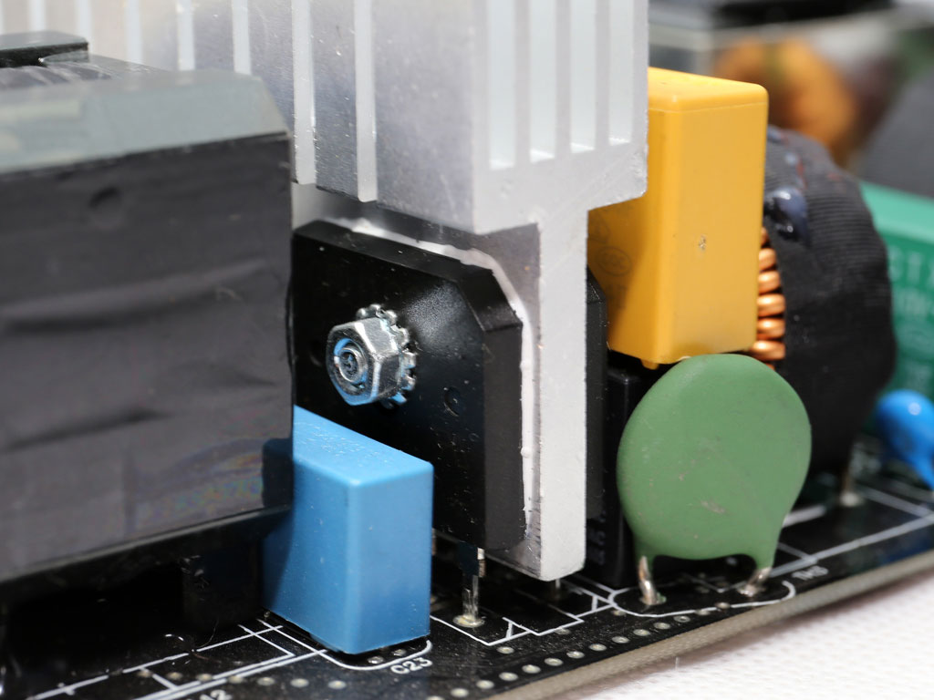
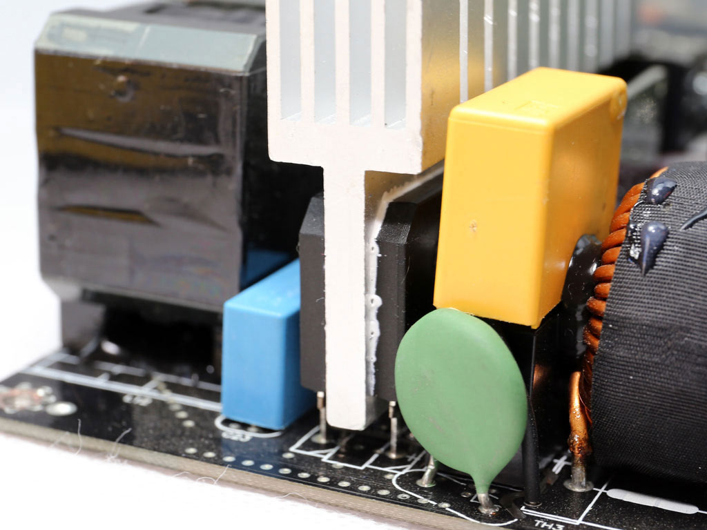
The soldering quality is very good. Andyson performed incredibly well in this area.
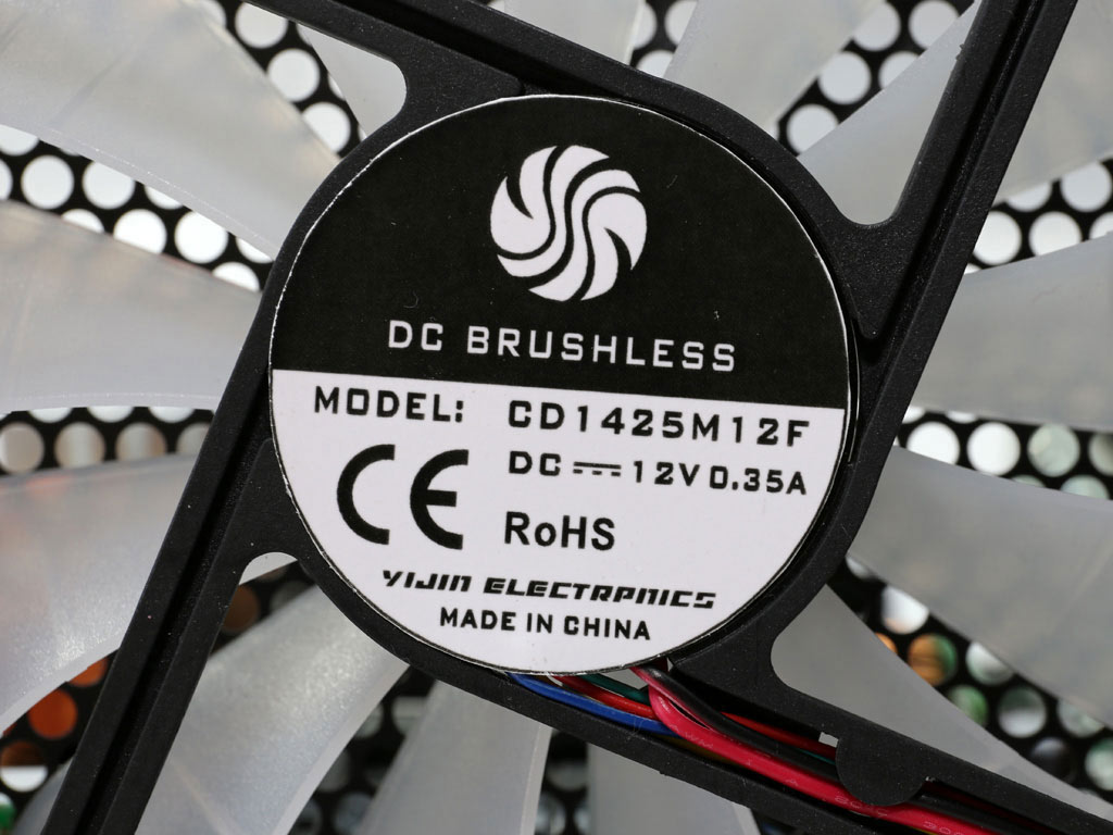
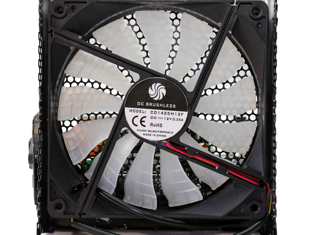
The fan uses an FDB bearing, and its maximum speed is restricted to make sure it isn't loud. In addition, it is controlled by a very relaxed fan profile.
Apr 17th, 2025 08:52 EDT
change timezone
Latest GPU Drivers
New Forum Posts
- Microcenter GPU Stock status (77)
- 5070 Ti power limit questions (43)
- Can,t download Windows 11 or 10. (9)
- RX 9000 series GPU Owners Club (355)
- Weird pc slow down as soon as PCI-E card is in the system (10)
- TPU's Nostalgic Hardware Club (20253)
- help needed (4)
- Is it worth buying a pi5 with a broken hdmi connector (8)
- SK hynix A-Die (Overclocking thread) only for RYZEN AM5 users (47)
- The TPU UK Clubhouse (26136)
Popular Reviews
- G.SKILL Trident Z5 NEO RGB DDR5-6000 32 GB CL26 Review - AMD EXPO
- ASUS GeForce RTX 5060 Ti TUF OC 16 GB Review
- NVIDIA GeForce RTX 5060 Ti PCI-Express x8 Scaling
- ASUS GeForce RTX 5080 TUF OC Review
- DAREU A950 Wing Review
- Palit GeForce RTX 5060 Ti Infinity 3 16 GB Review
- ASUS GeForce RTX 5060 Ti Prime OC 16 GB Review
- Zotac GeForce RTX 5060 Ti AMP 16 GB Review
- MSI GeForce RTX 5060 Ti Gaming OC 16 GB Review
- The Last Of Us Part 2 Performance Benchmark Review - 30 GPUs Compared
Controversial News Posts
- NVIDIA GeForce RTX 5060 Ti 16 GB SKU Likely Launching at $499, According to Supply Chain Leak (182)
- NVIDIA Sends MSRP Numbers to Partners: GeForce RTX 5060 Ti 8 GB at $379, RTX 5060 Ti 16 GB at $429 (127)
- Nintendo Confirms That Switch 2 Joy-Cons Will Not Utilize Hall Effect Stick Technology (105)
- Over 200,000 Sold Radeon RX 9070 and RX 9070 XT GPUs? AMD Says No Number was Given (100)
- Nintendo Switch 2 Launches June 5 at $449.99 with New Hardware and Games (99)
- NVIDIA Launches GeForce RTX 5060 Series, Beginning with RTX 5060 Ti This Week (92)
- Sony Increases the PS5 Pricing in EMEA and ANZ by Around 25 Percent (85)
- NVIDIA PhysX and Flow Made Fully Open-Source (77)