 0
0
Antec High Current Pro Platinum 1300 W Review
Voltage Regulation, Hold-up Time & Inrush Current »A Look Inside & Component Analysis
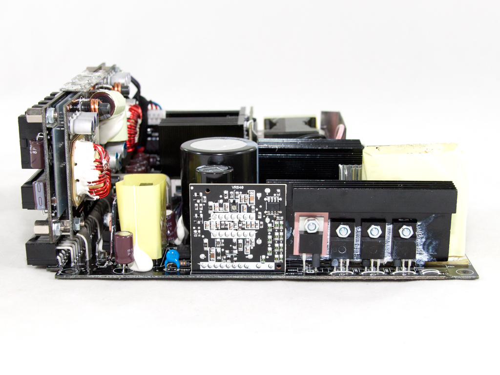
Before reading this page, we strongly suggest a look at this article, which will help you understand the internal components of a PSU much better. Our main tool for the disassembly of the PSU is a Thermaltronics TMT-9000S soldering and rework station. It is of extreme quality and is equipped with a matching de-soldering gun. With such equipment in hand, breaking apart every PSU is like a walk in the park!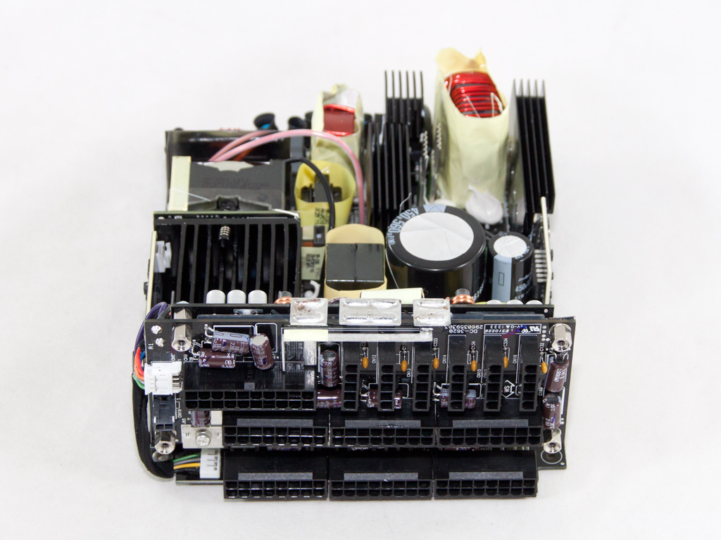

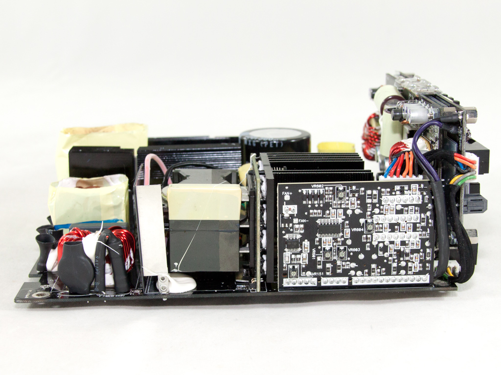
Like every other HCP unit, this one too is made by Delta, the largest and probably best PSU OEM. The only problem with Delta's implementations is that they are very expensive because their units only use topnotch components, and the best production lines in the industry also don't come cheap, nor are they cheap to maintain.
The HCP-1300 uses a full-bridge topology and an LLC converter for loss-less switching of the primary mosfets. The secondary side uses a synchronous rectification scheme with a specially designed transformer that actually hosts the +12V fets for reduced energy losses; the DC-DC converters are installed directly on the modular PCB for the same reason.
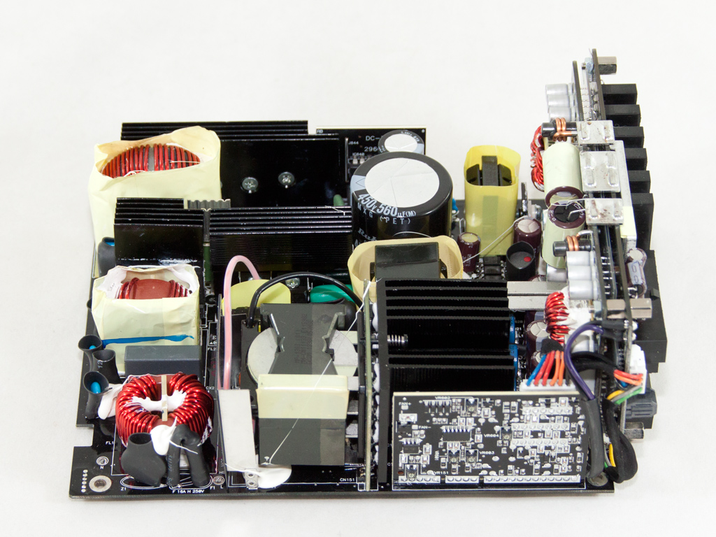
The first part of the transient filtering stage is located right behind the AC receptacle and consists of one X and two Y caps. We find the remaining transient filtering components, one X and four Y caps, two CM chokes, and an MOV, on the main PCB.
The two parallel bridge rectifiers are cooled by a dedicated heatsink. Their model number is LL25XB60 and they can, combined, handle up to 50 A of current. The PFC input cap is in front of the rectifier bridges.
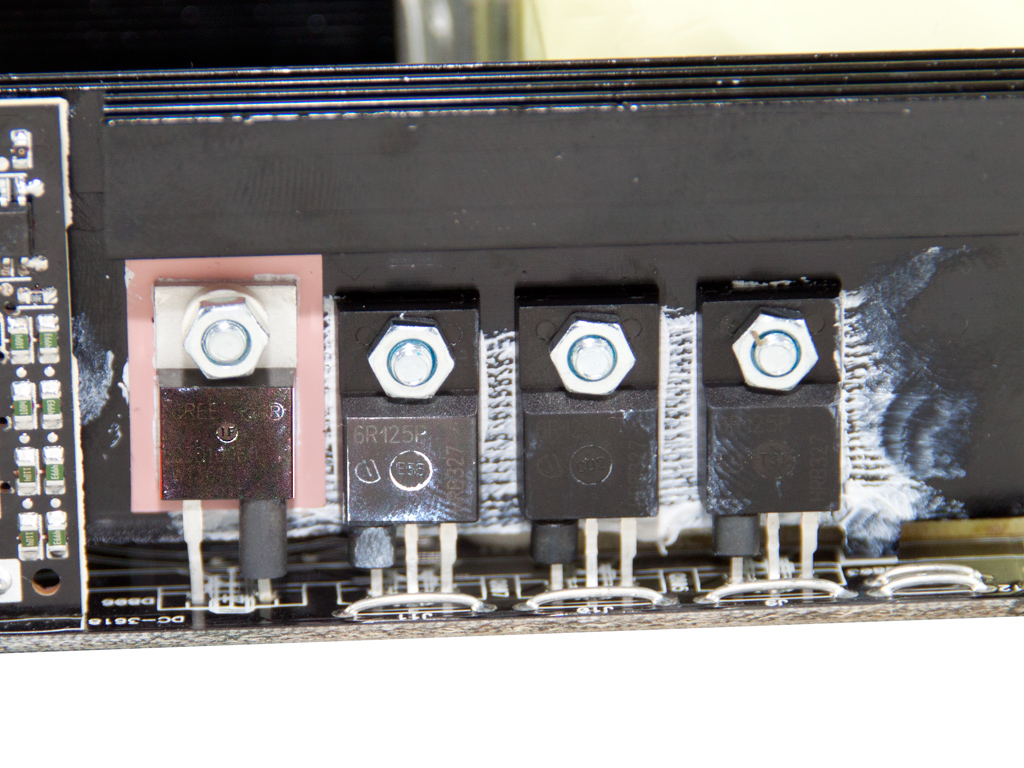
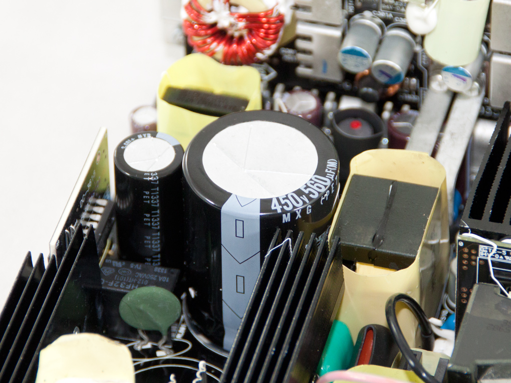
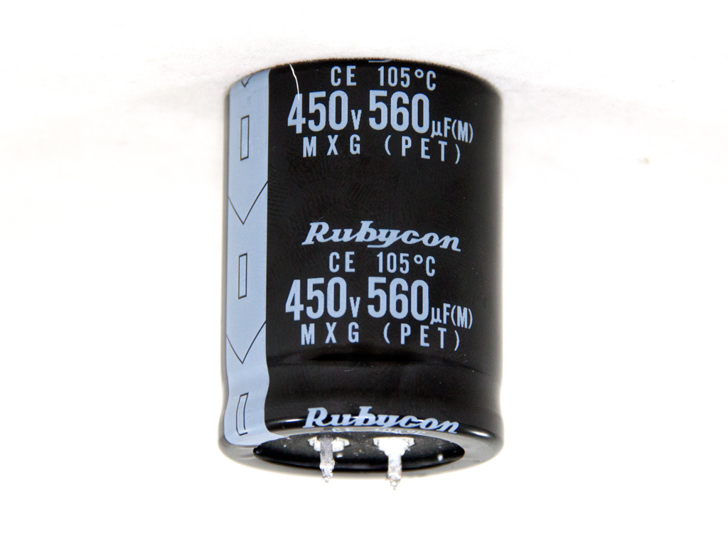
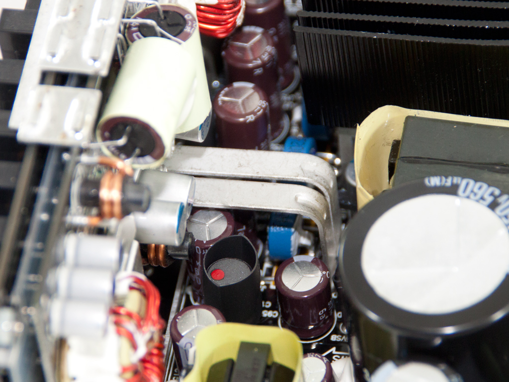
Three Infineon IPA60R125CP fets and a CREE C3D10060 boost diode are used in the APFC converter. The two huge parallel caps are provided by Rubycon (450V, 560µF each or 1120µF combined, 105°C, MXG series), and the PFC controller is mounted to a small PCB residing on the edge of the main PCB. It is a Champion CM6502S IC its maker says to meet 90+ efficiency.
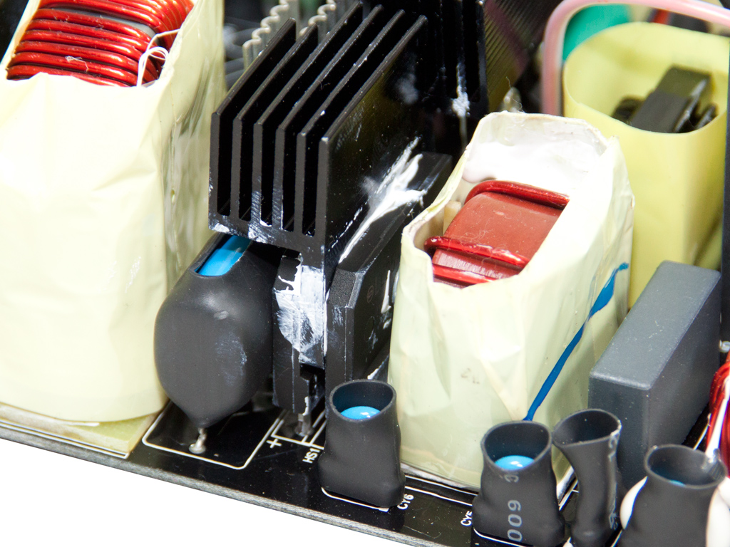
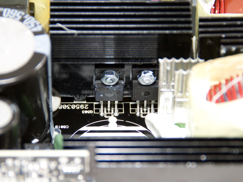
These heatsinks are attached to a couple resistors that are most likely used for current sense purposes.
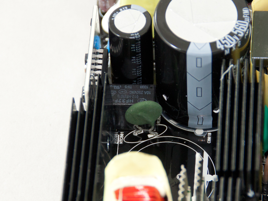
This thermistor is for large inrush current protection. Next to it resides a relay that cuts it off the circuit once the startup phase is complete.
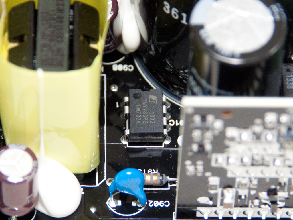
The standby PWM controller is a TNY280PG IC.
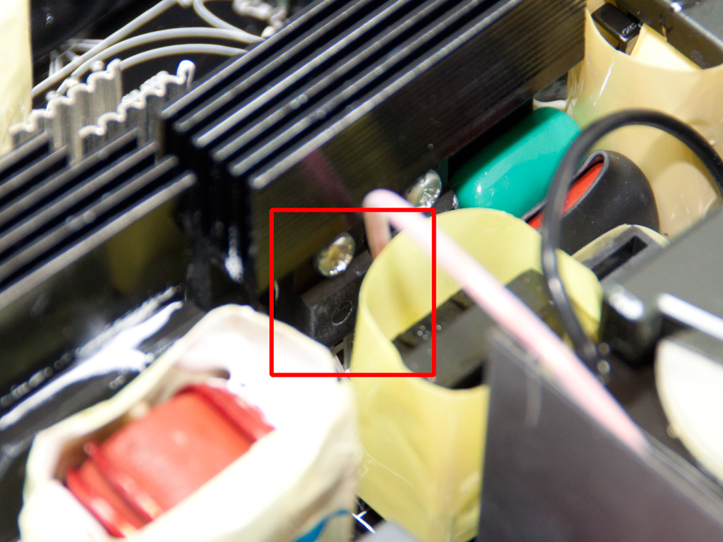
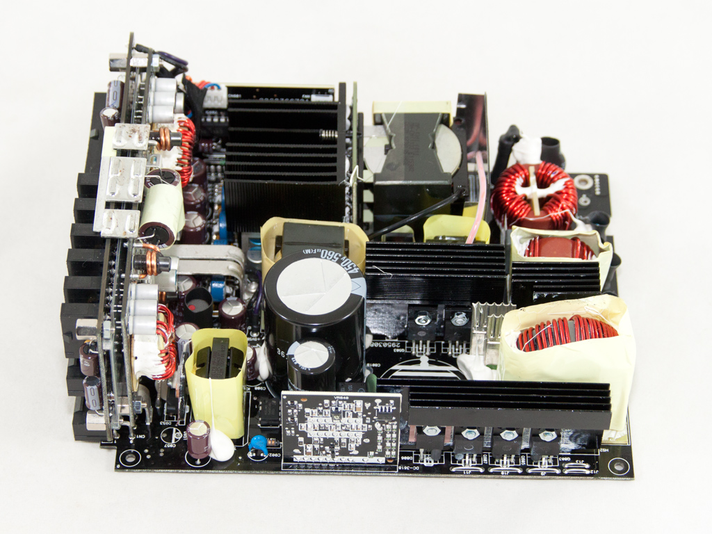
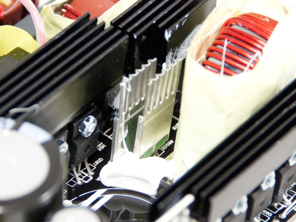
The four main switchers are arranged into a full bridge topology, and an LLC resonant converter here provides zero voltage switching to drastically decrease energy losses. The heatsink that cools down these fets is fairly small because of the low thermal load the switchers and LLC resonant converter produce.
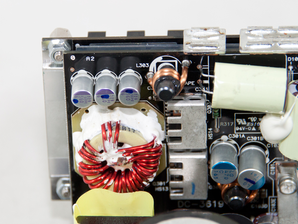
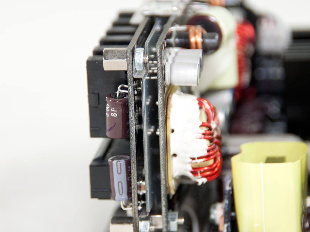
The main transformer is not only incredibly compact and densely populated, it also utilizes a special design that allows the fets that regulate the +12V rail to directly attach to it. This technique provides high efficiency and reduces EMI noise. As you can see in the photos above, a small heatsink is firmly attached to the +12V fets to cool them down. Finally, a great number of solid capacitors and several Nippon Chemi-Con electrolytic caps are used to filter the +12V rail.

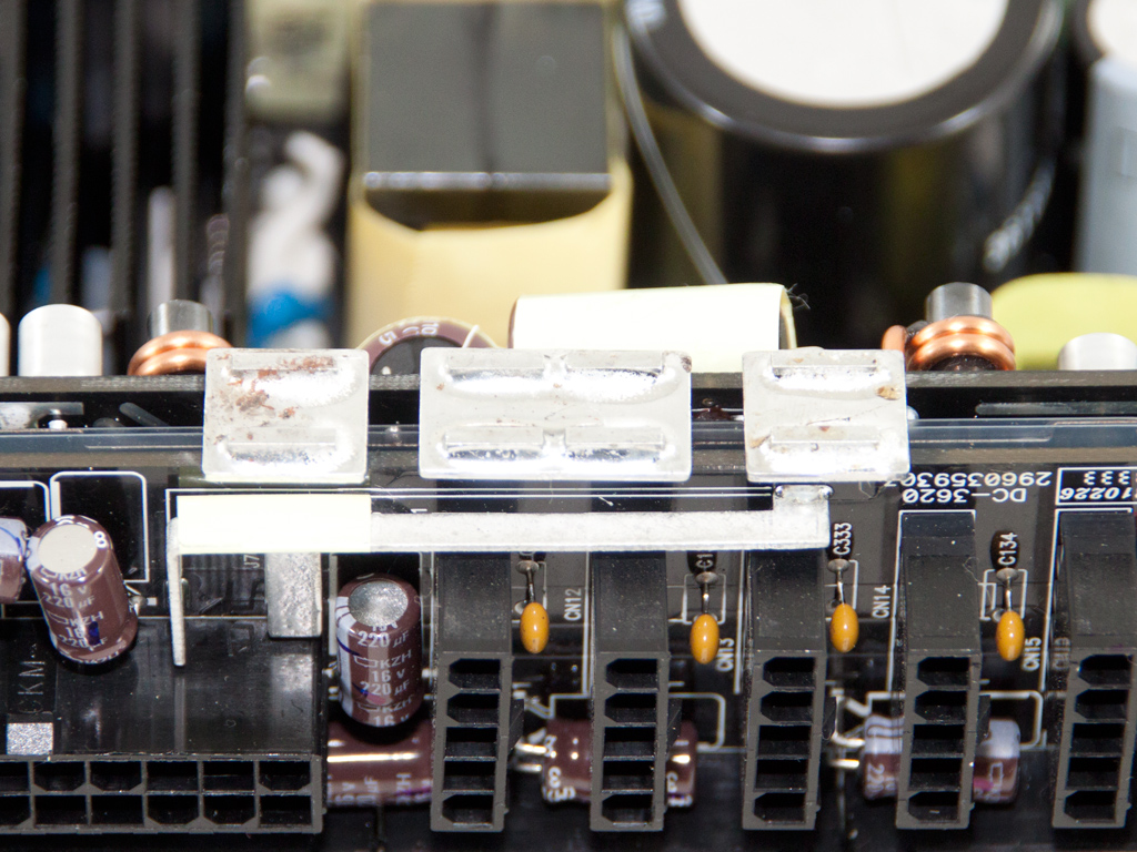
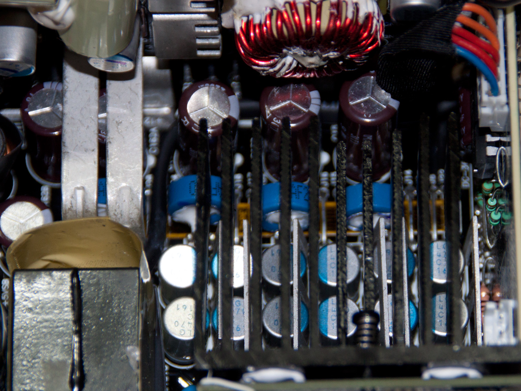
Two DC-DC converters that generate the minor rails are located on a PCB right behind the modular one. Several bus bars transfer the required power (+12V) along with ground to this PCB, and two pairs of fets behind it each handle the two minor rails. Two solid capacitors and two large Chemi-Con electrolytics further reduce/filter ripple. This PCB is connected to the modular one via three bus bars located at its very top.
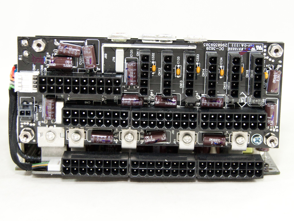
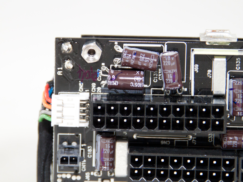
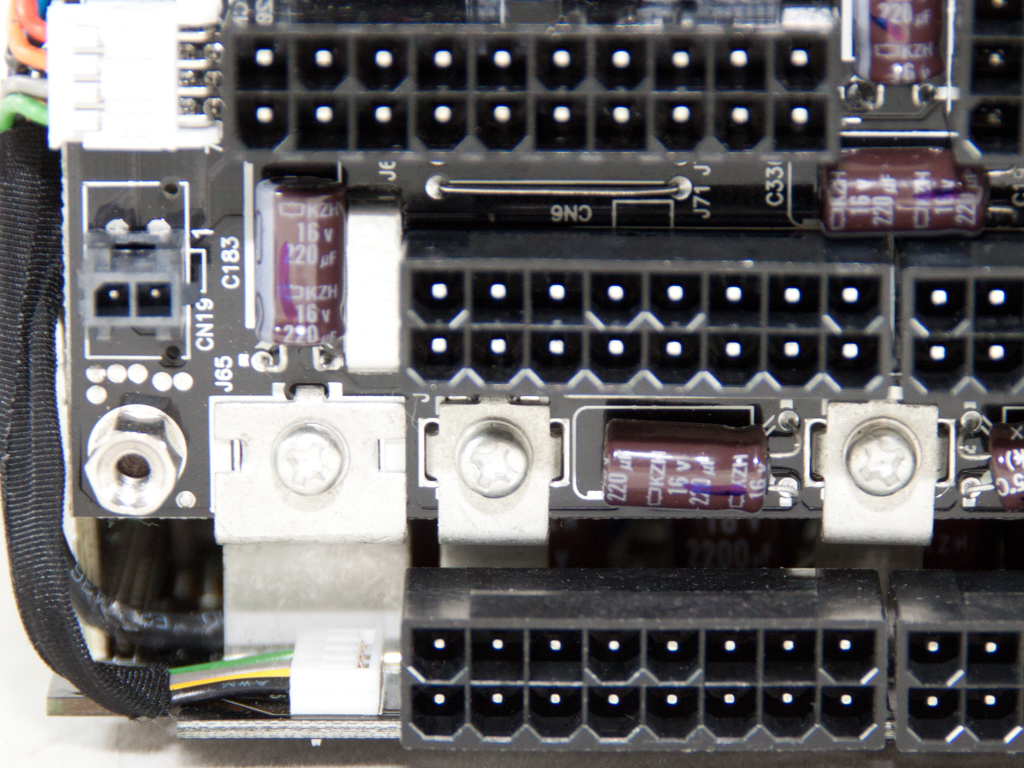
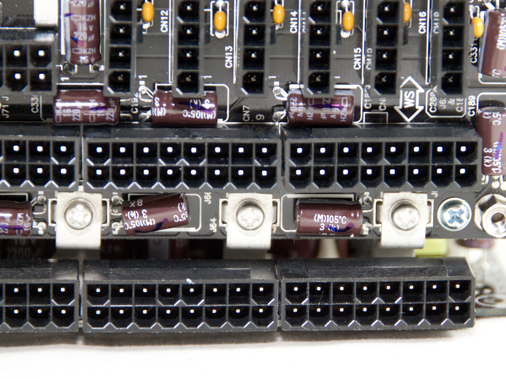
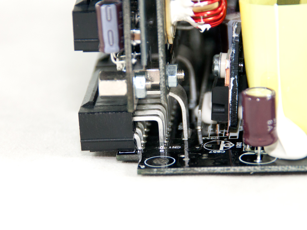
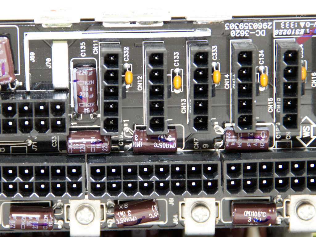
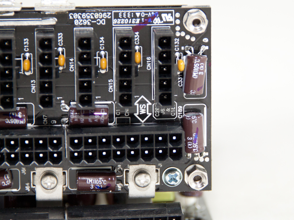
On the modular PCB, many Chemi-Con electrolytic caps provide some extra ripple filtering to the DC outputs. The bottom sockets are directly soldered to the main PCB to keep wiring to a minimum, which also keeps forward voltage drops at high loads at an all-time low.
The modular board consists of three layers.
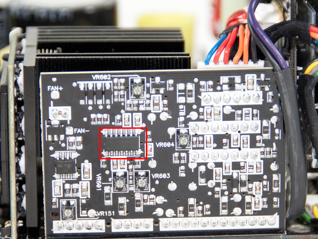
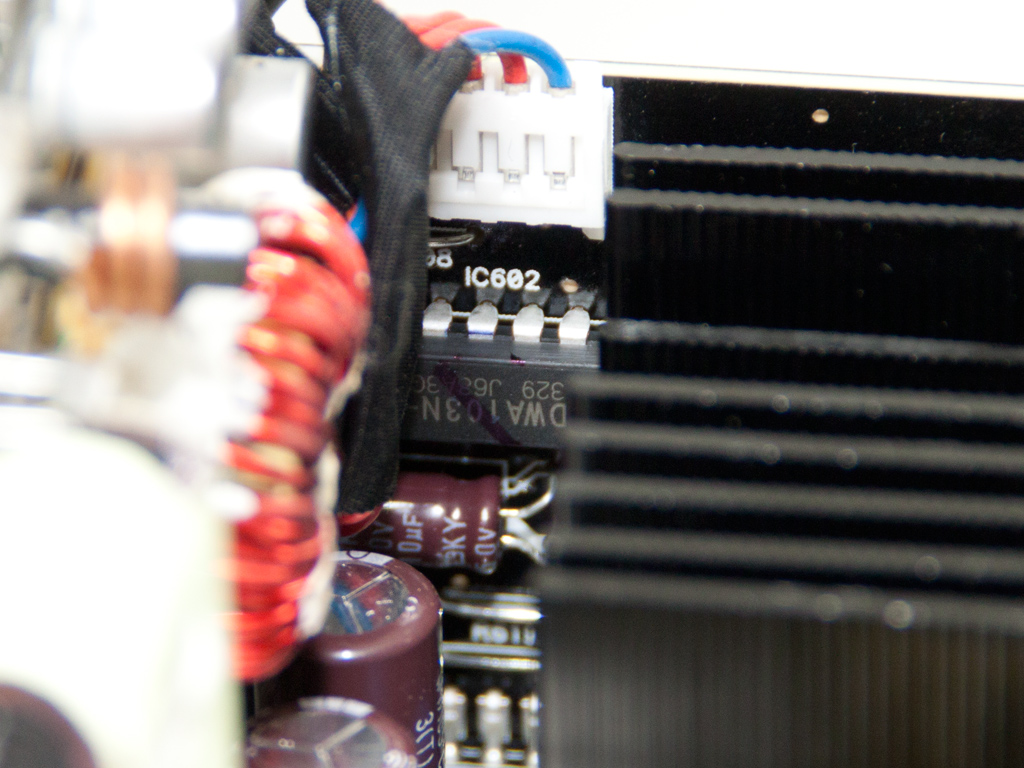
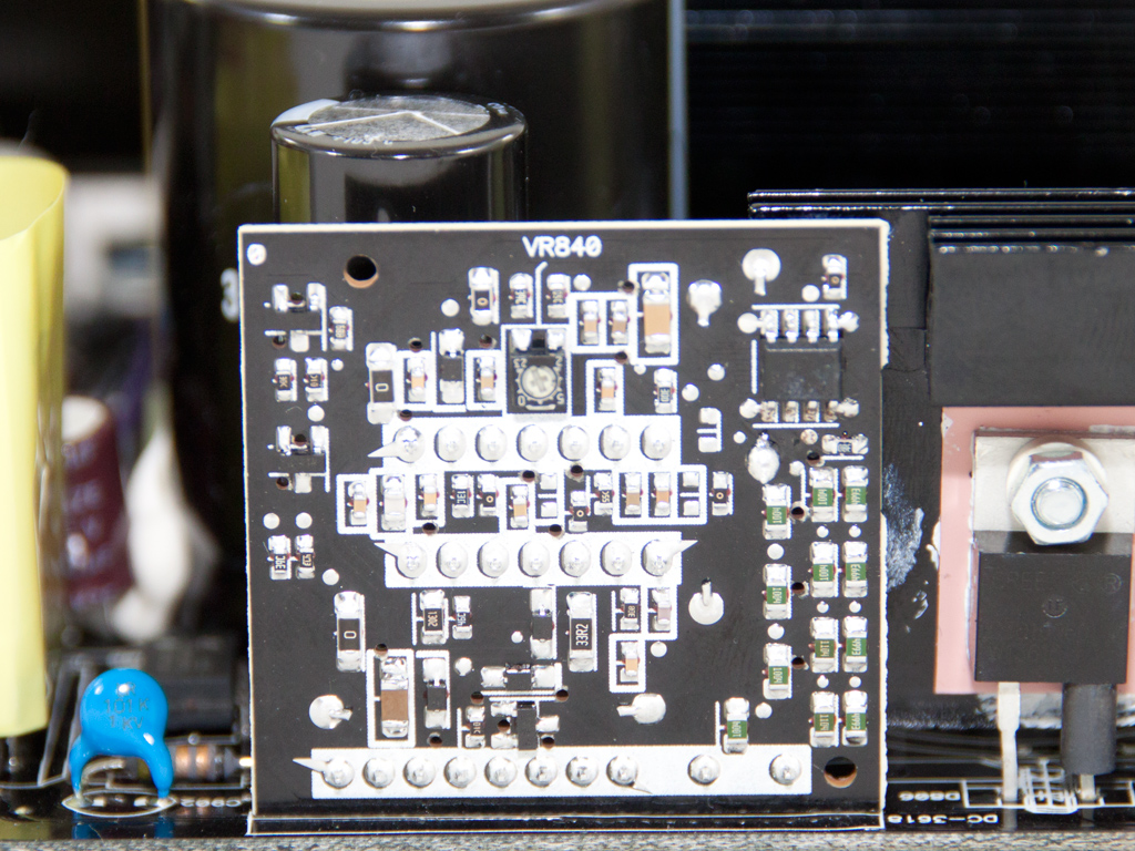
The supervisor IC is located on a vertical PCB in the secondary side. Its model number is DWA103N, and exactly the same one is used in the HCP-1000 and older HCP-1200. An AS339 quad voltage comparator on the solder side of the same PCB also provides a few additional OCP channels.
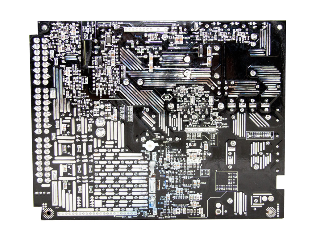
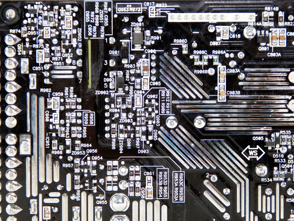
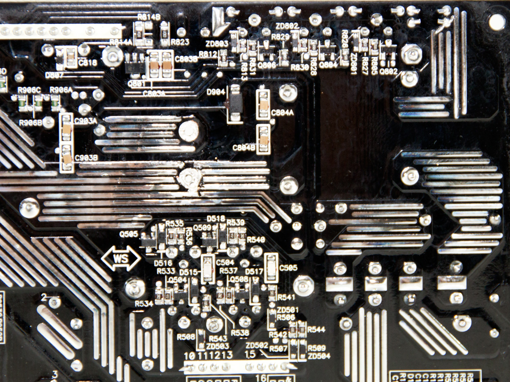
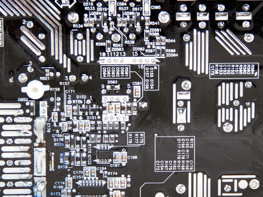
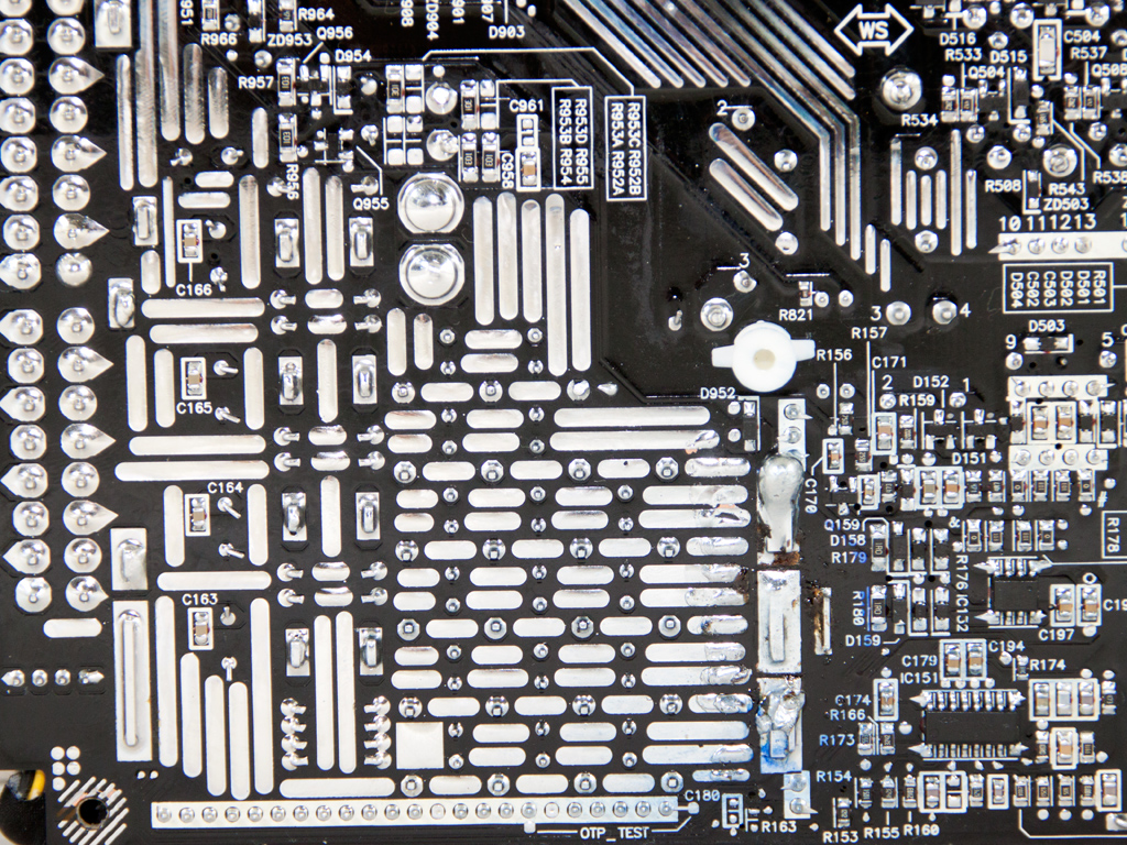
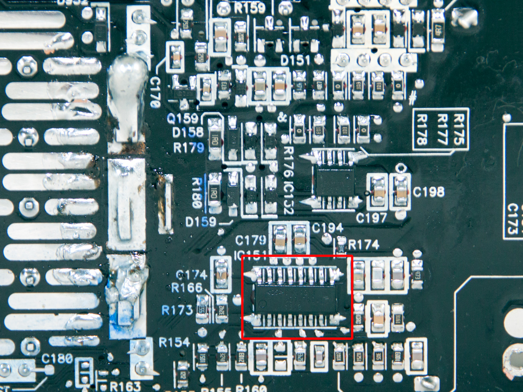
Soldering quality on the main PCB is very good; however, we spotted some areas where soldering wasn't up to the typical Delta levels. We also found the LLC resonant controller on this side. It is a Champion CM6901X IC. The CM6901 operates in PWM mode at light loads, using FM mode for everything else.
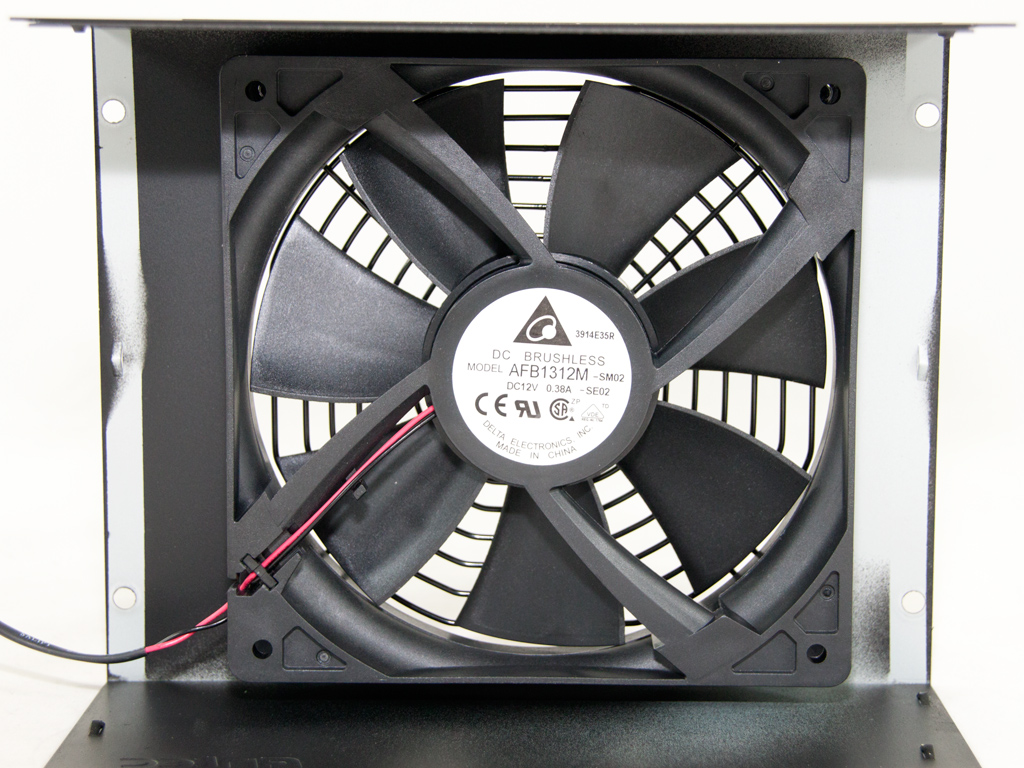
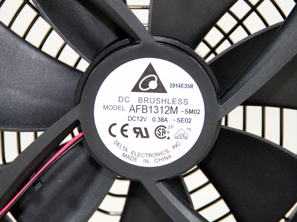
The cooling fan is made by Delta, since Delta also has a long-standing tradition as a fan manufacturer. The fan's model number is AFB1312M (12V, 0.38A), and it is manufactured in China. The fan's profile stays pretty relaxed at up to about 60% of the maximum-rated-capacity load under normal conditions, but goes all out afterward to keep the unit's internals cool.
Apr 8th, 2025 10:02 EDT
change timezone
Latest GPU Drivers
New Forum Posts
- is it worth using ssd with usb2? (23)
- 9070XT or 7900XT or 7900XTX (134)
- ## [Golden Sample] RTX 5080 – 3300 MHz @ 1.020 V (Stock Curve) – Ultra-Stable & Efficient (9)
- Is RX 9070 VRAM temperature regular value or hotspot? (334)
- 12v lines 0 reads occansionally (5)
- Steam Deck Owners Clubhouse (496)
- Microcenter GPU Stock status (70)
- The coffee and tea drinkers club. (252)
- What's your latest tech purchase? (23499)
- RTX5000 Series Owners Club (165)
Popular Reviews
- The Last Of Us Part 2 Performance Benchmark Review - 30 GPUs Compared
- UPERFECT UStation Delta Max Review - Two Screens In One
- PowerColor Radeon RX 9070 Hellhound Review
- ASUS Prime X870-P Wi-Fi Review
- MCHOSE L7 Pro Review
- Upcoming Hardware Launches 2025 (Updated Apr 2025)
- Sapphire Radeon RX 9070 XT Pulse Review
- Sapphire Radeon RX 9070 XT Nitro+ Review - Beating NVIDIA
- Corsair RM750x Shift 750 W Review
- DDR5 CUDIMM Explained & Benched - The New Memory Standard
Controversial News Posts
- NVIDIA GeForce RTX 5060 Ti 16 GB SKU Likely Launching at $499, According to Supply Chain Leak (161)
- MSI Doesn't Plan Radeon RX 9000 Series GPUs, Skips AMD RDNA 4 Generation Entirely (146)
- Microsoft Introduces Copilot for Gaming (124)
- AMD Radeon RX 9070 XT Reportedly Outperforms RTX 5080 Through Undervolting (119)
- NVIDIA Reportedly Prepares GeForce RTX 5060 and RTX 5060 Ti Unveil Tomorrow (115)
- Over 200,000 Sold Radeon RX 9070 and RX 9070 XT GPUs? AMD Says No Number was Given (100)
- NVIDIA GeForce RTX 5050, RTX 5060, and RTX 5060 Ti Specifications Leak (97)
- Nintendo Switch 2 Launches June 5 at $449.99 with New Hardware and Games (95)