 72
72
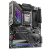
ASRock X870E Taichi Review
Component Analysis »Board Layout
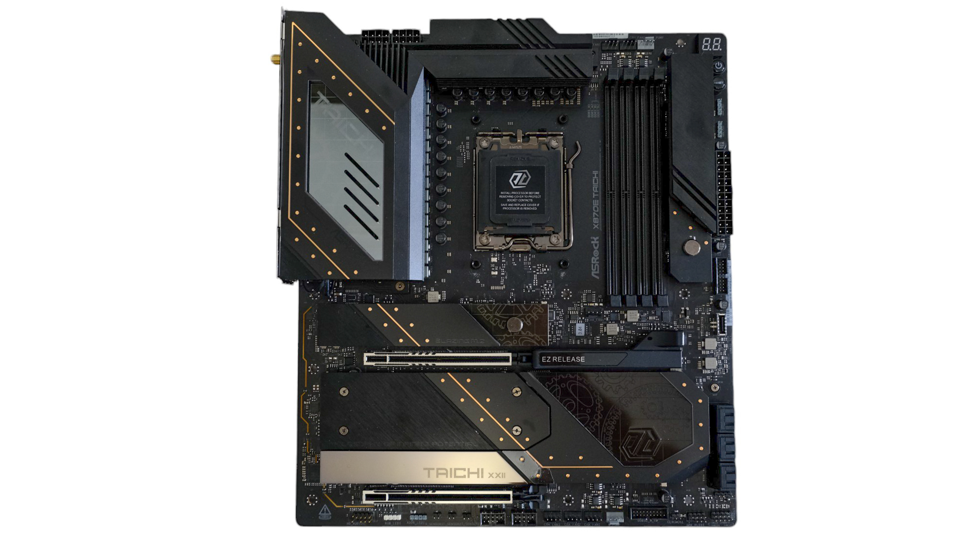

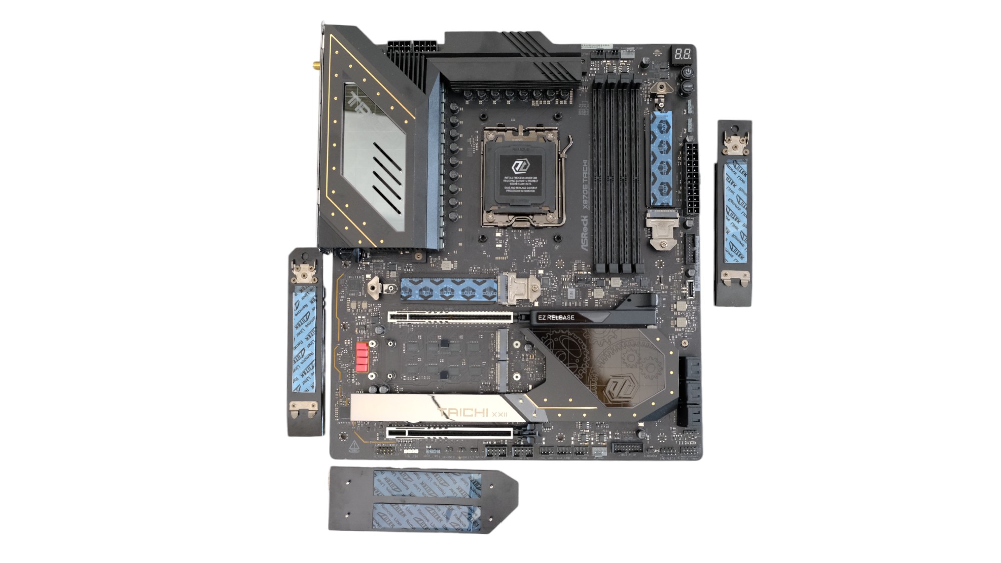
ASRock's RGB features include three 5 V/3 A ARGB 3-pin headers plus a 12 V/3 A 4-pin header, as well as a row of ARGB LEDs underneath the chipset heatsink on the south end of the board and layered display ARGB LEDs embedded beneath acrylic panels on top of the I/O shroud illuminating the familiar Taichi cogwheels. The rest of the board is a predominantly black design, but the PCB is relatively spacious thanks to its E-ATX dimensions adding some width and allowing for one of the three PCIe 4.0 M.2 slots to be sandwiched between the 24-pin ATX connector and DIMM slots.


This is usually a preferred location in terms of cooling and accessibility, sitting closer to any case front fans and not being blocked by your graphics card. ASRock's tool-free features extend to the M.2 heatsinks and the primary 16x PCIe slot. The latter has a sprung pull-latch that locks in place once your graphics card is installed and released by pulling it away from the slot. This works brilliantly and feels safer and easier to use than ASUS' method of simply lifting the card up from the port end, which doesn't work every time. No such problem here so well done ASRock.
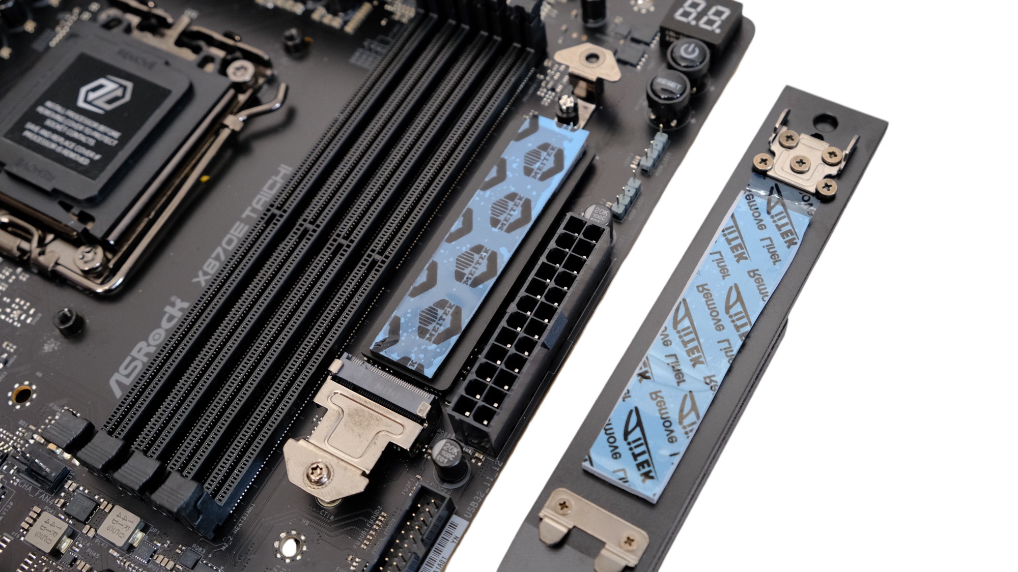
The single PCIe 5.0 M.2 slot sits far enough above the primary 16x slot to ensure good clearance from backplate-equipped graphics cards, but its size likely means running PCIe 5.0 SSDs flat out may well see them throttle. We'll be testing that out later. The lower two M.2 ports sit under a single large heatsink, which is a lot smaller than that on the ASUS ROG Crosshair X870E Hero, but here it only has to cool two SSDs rather than four. It's a little easier to align the four captive screws, but still a bit fiddly. The sooner those tool-free features find their way to all M.2 ports the better.
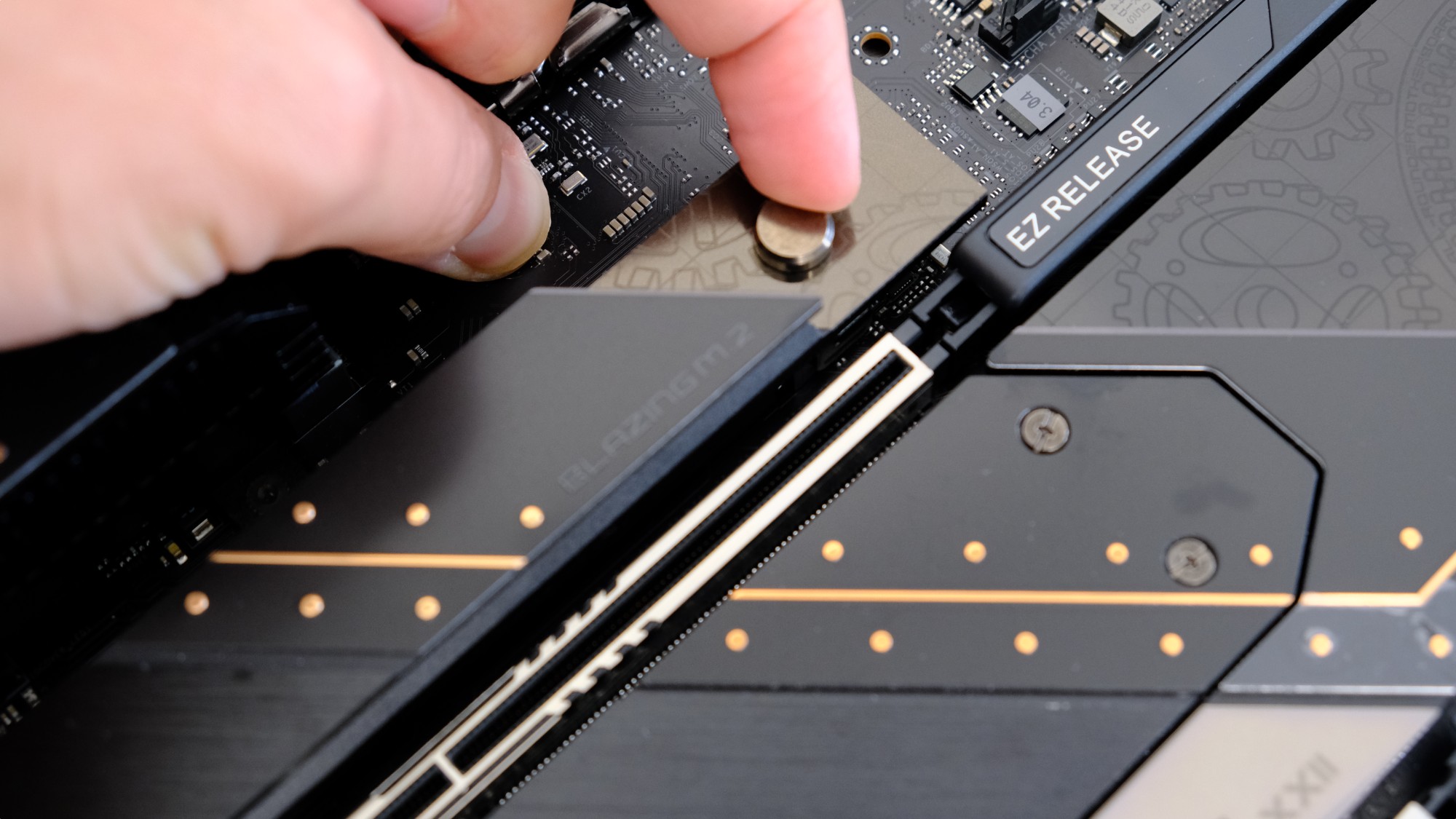

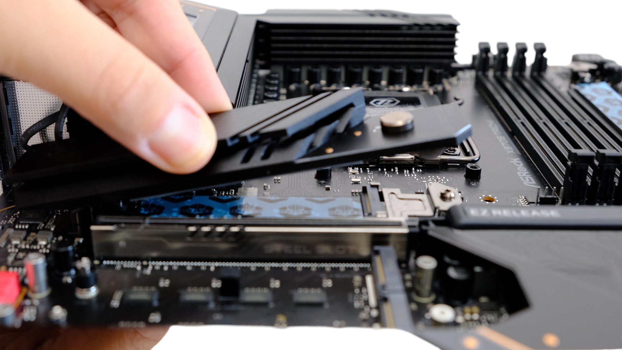
The slot above the graphics card and the one next to the 24-pin ATX connector feature top and bottom heatsinks cooling both sides of the SSD and the heatsink itself is tool free, detaching by sliding the small cylindrical latch forwards, with the usual rotating plastic clip holding the SSD itself in place. This works well, but you generally need two hands to remove the heatsink, whereas MSI and ASUS' implementations just require a single hand to unlock and lift the heatsink.

These heatsinks are similar enough so they can fit in each other's slot, but there's no reason to swap them over as they perform identically and have patterns on top that align with the rest of the board. The slot above the graphics card is the only slot that supports PCIe 5.0 SSDs, so you get more flexibility here opting for more expensive boards. For PCIe 3.0 or PCIe 4.0 M.2 SSD owners, it's a question of where is best to place your SSD in terms of access and temperatures.
You can see the detailed temperature testing a few pages on under SSD performance and temperatures, but the short story is that the slot near the 24-pin ATX connector is the best place by far to house your SSD, followed by the slot above your graphics card. The slots that sit under your graphics card get little airflow, and both get blasted with warm air and are also blocked by your graphics card when installed. It's unlikely even the hottest-running PCIe 4.0 SSD would throttle even under sustained workloads, but given the much lower temperatures, easier installation and removal, it makes little sense to use these slots given the choice.

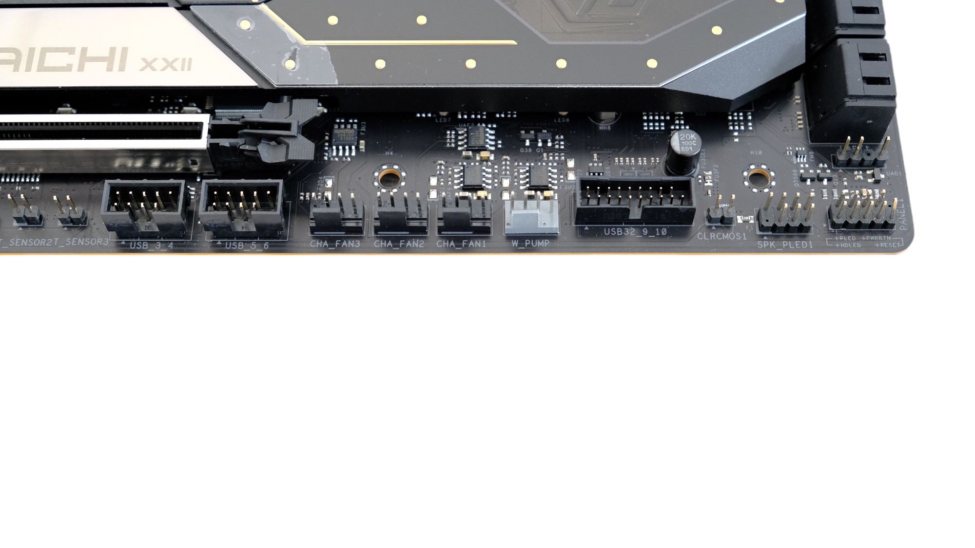
Above we can see a bunch of 2-pin headers and these are for thermal probes that are included in the box. These are useful for attaching to different areas of your case as they can be tied to particular fans in the software or EFI fan control to boost airflow in those areas. Also, very useful for attaching a coolant thermal probe for watercooling purposes so you can control radiator fan speed using the coolant temperature and not CPU temperature. The only issue here is ASRock's EFI and software is a little clunky to use for detailed fan control - something we'd like to see ASRock improve. More on that in a minute. The CPU header is limited to 1 A/12 W, and we're waiting on clarification from ASRock whether the remaining seven 4-pin fan headers are limited to 3 A/36 W in total or per port, as this isn't clear in the manual.

The rest of the PCB is fairly standard with no fancy 60 W Type-C USB header - just your typical USB 3.2 Gen 2x2 20 Gbps header, six SATA ports with a split of two ports to one X870E chipset and four to the other X870E chipset on the PCB. The I/O panel is perhaps a little less interesting than those of other X870 boards, with many opting for a Type-C heavy layout, but here there's just two, which of course both support USB4 40 Gbps plus PD 3.0 up to 15 W. You get more Type-A ports in return with two of these being what ASRock calls Lightning Gaming Ports that run off separate controller interfaces and claim to reduce jitter and latency.

Another two feature Ultra USB Power, where the 5 V supply is derived from a 12 V rail that fluctuates less than a typical 5 V rail under heavy loads and shields it from noise from other devices such as RGB lighting for better audio quality on devices connected to those ports. The rest are a mixture of USB 3.2 Gen 2, Gen 1 and USB 2.0. Also on the I/O panel are CMOS clear and USB BIOS Flashback buttons, an HDMI 2.1 port, antenna connections for the Wi-Fi 7 module, a 5 Gbps Realtek RTL8126 Ethernet port and audio ports for the Realtek ALC4082 codec.
Apr 7th, 2025 22:39 EDT
change timezone
Latest GPU Drivers
New Forum Posts
- is it worth using ssd with usb2? (10)
- Question about Intel Optane SSDs (70)
- USB case with dual USB-C and dual USB-A (6)
- The TPU UK Clubhouse (26058)
- Help me pick a UPS (88)
- Anyone with true HDDs still around here? (336)
- 12v lines 0 reads occansionally (2)
- Someone run games on AMD BC-250 under Linux * Cut down PS5 die to 6 CPU cores 24 GPU cores for use in crypto mining (79)
- RX 9000 series GPU Owners Club (236)
- The coffee and tea drinkers club. (246)
Popular Reviews
- The Last Of Us Part 2 Performance Benchmark Review - 30 GPUs Compared
- UPERFECT UStation Delta Max Review - Two Screens In One
- ASUS Prime X870-P Wi-Fi Review
- PowerColor Radeon RX 9070 Hellhound Review
- Upcoming Hardware Launches 2025 (Updated Apr 2025)
- Sapphire Radeon RX 9070 XT Pulse Review
- MCHOSE L7 Pro Review
- Corsair RM750x Shift 750 W Review
- Sapphire Radeon RX 9070 XT Nitro+ Review - Beating NVIDIA
- DDR5 CUDIMM Explained & Benched - The New Memory Standard
Controversial News Posts
- NVIDIA GeForce RTX 5060 Ti 16 GB SKU Likely Launching at $499, According to Supply Chain Leak (159)
- MSI Doesn't Plan Radeon RX 9000 Series GPUs, Skips AMD RDNA 4 Generation Entirely (146)
- Microsoft Introduces Copilot for Gaming (124)
- AMD Radeon RX 9070 XT Reportedly Outperforms RTX 5080 Through Undervolting (119)
- NVIDIA Reportedly Prepares GeForce RTX 5060 and RTX 5060 Ti Unveil Tomorrow (115)
- Over 200,000 Sold Radeon RX 9070 and RX 9070 XT GPUs? AMD Says No Number was Given (100)
- NVIDIA GeForce RTX 5050, RTX 5060, and RTX 5060 Ti Specifications Leak (97)
- Nintendo Switch 2 Launches June 5 at $449.99 with New Hardware and Games (92)