 9
9
ASUS ROG Falchion Review
Software »Disassembly


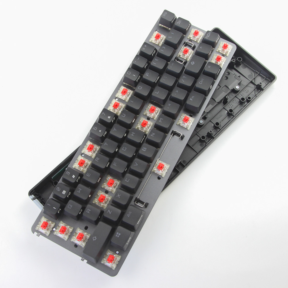

Disassembly of the ASUS ROG Falchion is on the simpler side of things with 12 Phillips head screws holding the plate/PCB in place on the ABS plastic case. Accessing them involves removing multiple keycaps as seen above, and a precision screwdriver will come in handy here. At this point, lift the plate and PCB up together, but be careful since two cables connect the primary PCB to the case.


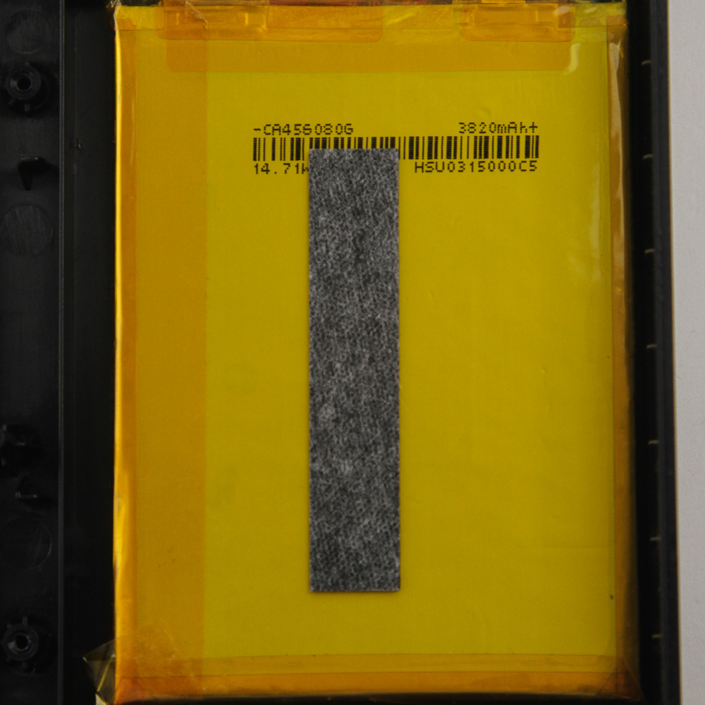

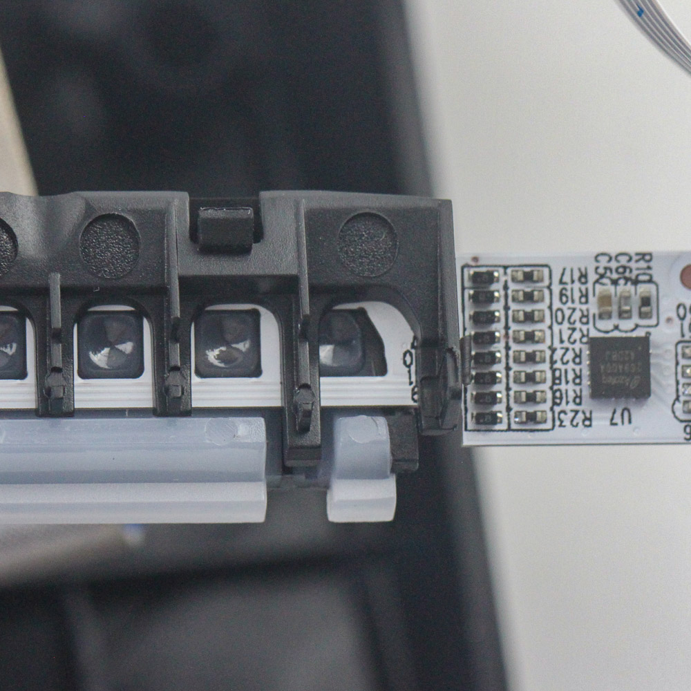
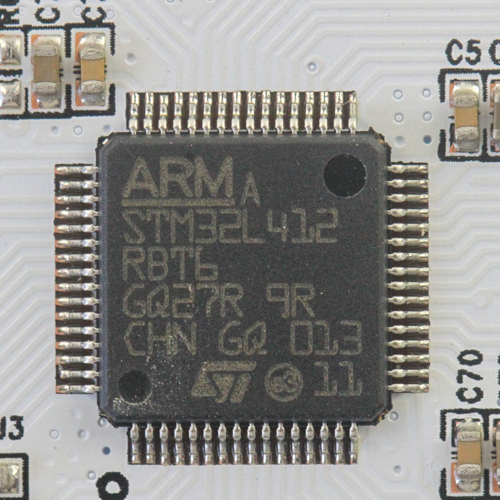
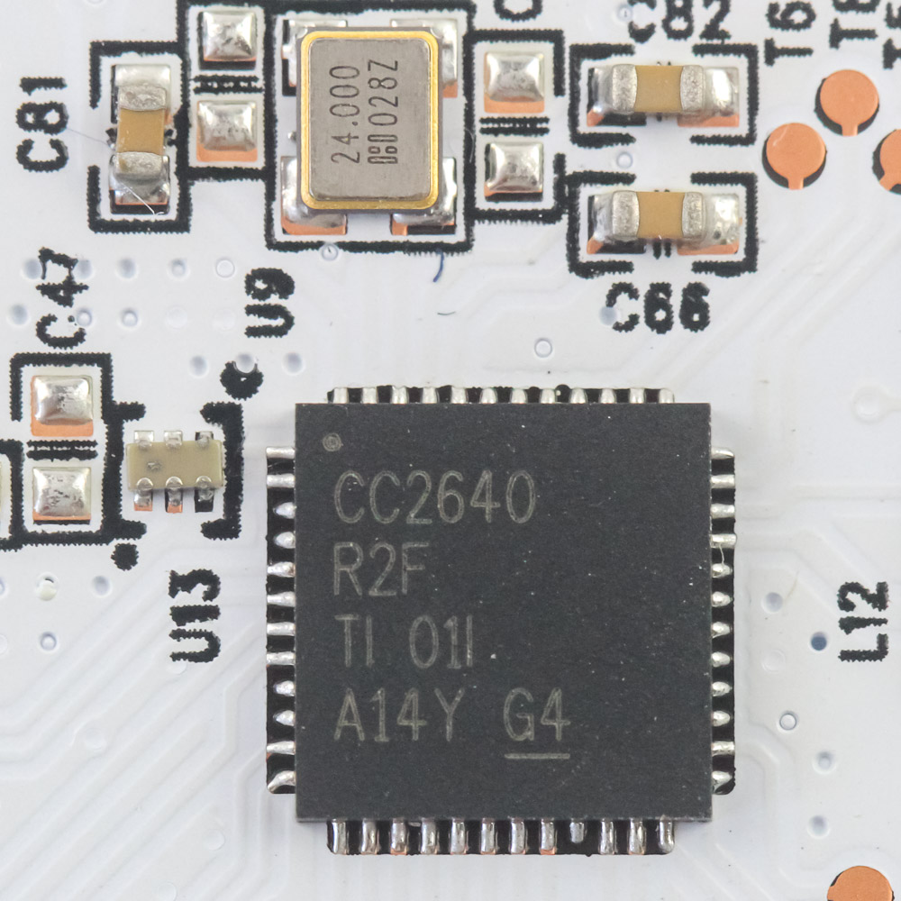
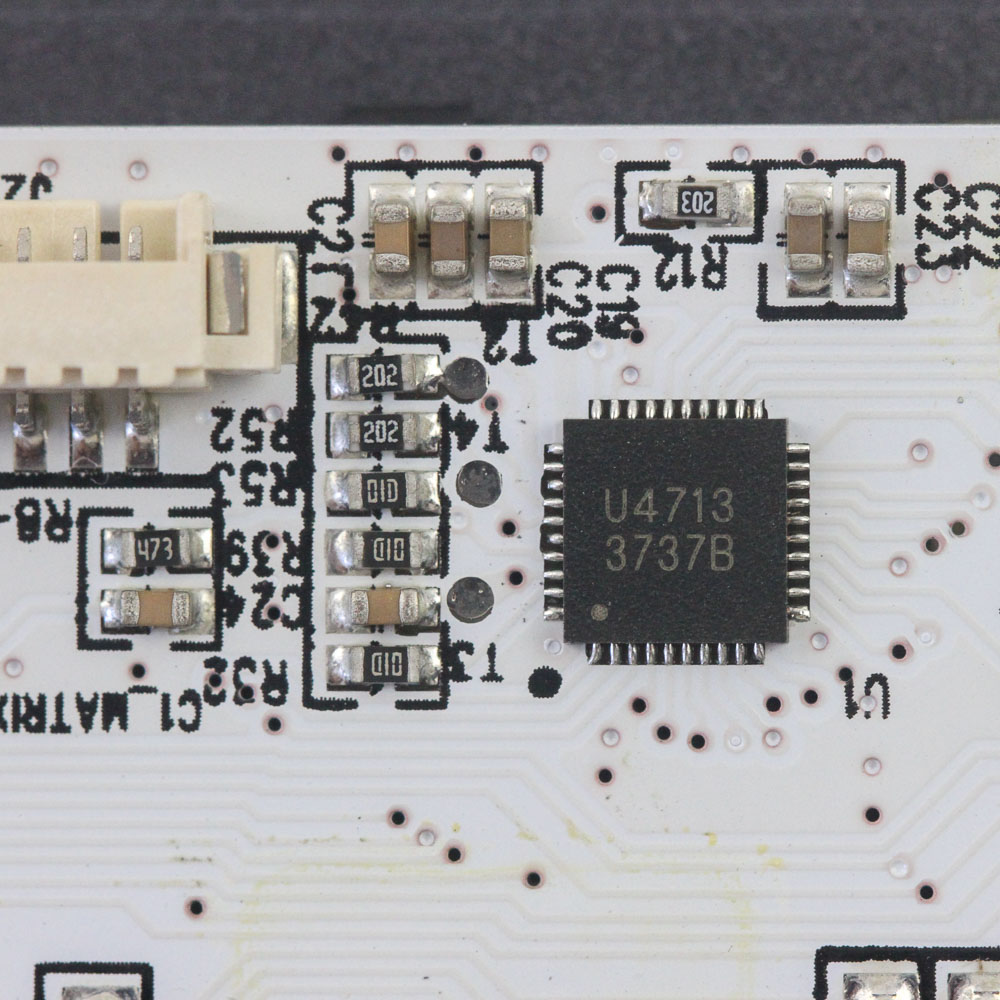
With both connectors dislodged, you can fully separate the two, and there is actually more going on with the case housing multiple items of interest. There are eight more screws to tackle here, as well as a grounding connector to dislodge before we can examine it all, including the 3820 mAh Li-ion battery underneath the shielded cover. There is also a daughter PCB, which really is the brains of the entire operation and acts as a conduit to the battery and switches/LEDs on the primary PCB while handling both wired and wireless connectivity in addition to the touchpad on the side. Powering the keyboard is an STMicroelectronics STM32L412R8 Arm Cortex-M4 microcontroller with 64 KB of onboard flash memory for all the pre-programmed functions. We saw it put to good use on the ROG Claymore II, and it is a higher-performance MCU than typically seen on keyboards.
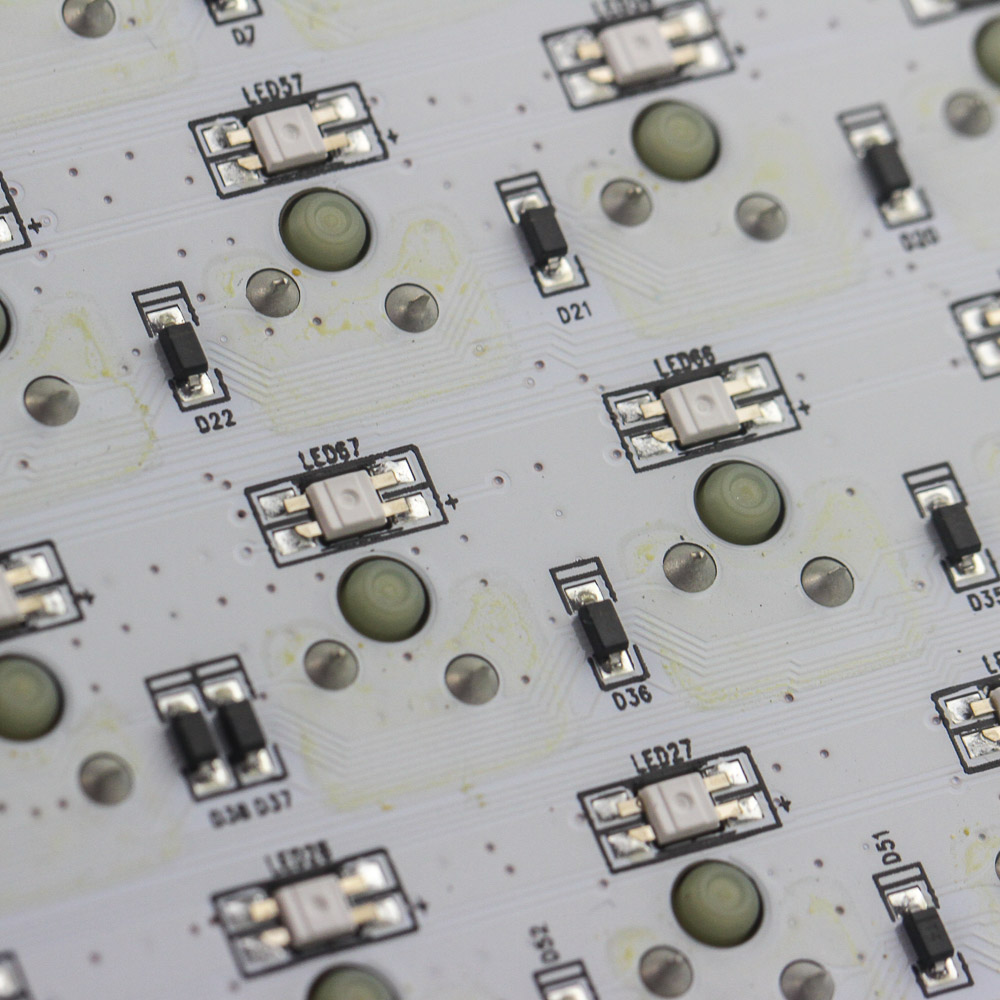
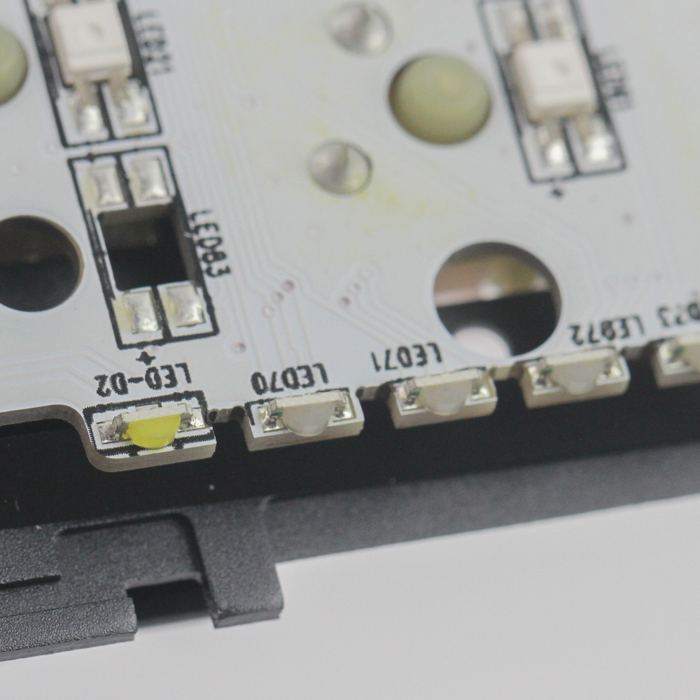
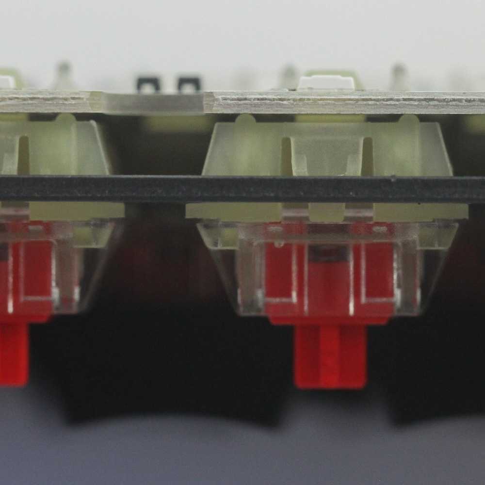
The primary PCB is also white, and solder quality is exceptional throughout. The switches are indeed soldered through the plate and onto the PCB, with an SMD RGB LED associated with each. There are some extra LEDs on the left side we saw used with the plastic diffuser for the indicator LEDs. As is the norm, all the components are soldered onto a multi-layer PCB.
Before we move on, be advised that disassembly may void the warranty and that TechPowerUp is not liable for any damages incurred if you decide to go ahead and do so anyway.
Apr 7th, 2025 22:37 EDT
change timezone
Latest GPU Drivers
New Forum Posts
- Question about Intel Optane SSDs (70)
- is it worth using ssd with usb2? (9)
- USB case with dual USB-C and dual USB-A (6)
- The TPU UK Clubhouse (26058)
- Help me pick a UPS (88)
- Anyone with true HDDs still around here? (336)
- 12v lines 0 reads occansionally (2)
- Someone run games on AMD BC-250 under Linux * Cut down PS5 die to 6 CPU cores 24 GPU cores for use in crypto mining (79)
- RX 9000 series GPU Owners Club (236)
- The coffee and tea drinkers club. (246)
Popular Reviews
- The Last Of Us Part 2 Performance Benchmark Review - 30 GPUs Compared
- UPERFECT UStation Delta Max Review - Two Screens In One
- ASUS Prime X870-P Wi-Fi Review
- PowerColor Radeon RX 9070 Hellhound Review
- Upcoming Hardware Launches 2025 (Updated Apr 2025)
- Sapphire Radeon RX 9070 XT Pulse Review
- MCHOSE L7 Pro Review
- Corsair RM750x Shift 750 W Review
- Sapphire Radeon RX 9070 XT Nitro+ Review - Beating NVIDIA
- DDR5 CUDIMM Explained & Benched - The New Memory Standard
Controversial News Posts
- NVIDIA GeForce RTX 5060 Ti 16 GB SKU Likely Launching at $499, According to Supply Chain Leak (159)
- MSI Doesn't Plan Radeon RX 9000 Series GPUs, Skips AMD RDNA 4 Generation Entirely (146)
- Microsoft Introduces Copilot for Gaming (124)
- AMD Radeon RX 9070 XT Reportedly Outperforms RTX 5080 Through Undervolting (119)
- NVIDIA Reportedly Prepares GeForce RTX 5060 and RTX 5060 Ti Unveil Tomorrow (115)
- Over 200,000 Sold Radeon RX 9070 and RX 9070 XT GPUs? AMD Says No Number was Given (100)
- NVIDIA GeForce RTX 5050, RTX 5060, and RTX 5060 Ti Specifications Leak (97)
- Nintendo Switch 2 Launches June 5 at $449.99 with New Hardware and Games (92)