 27
27
Biostar TZ68A+ LGA1155 Review
BIOS Walkthrough »The Board - A Closer Look
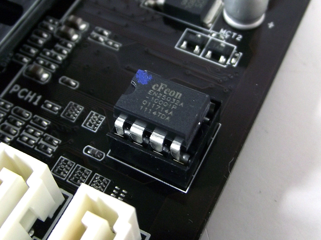
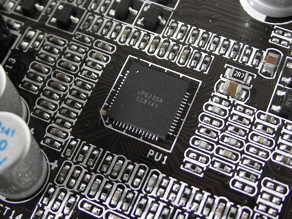
Our usual first item to look at, of course, if the BIOS chip itself, nestled securely in a socket that makes user replacement fairly simple. The second image shows the TZ68A+'s VRM controller, the UPI uP6235A, which is actually capable of controlling twice the number of power phases we find on the Biostar TZ68A+.
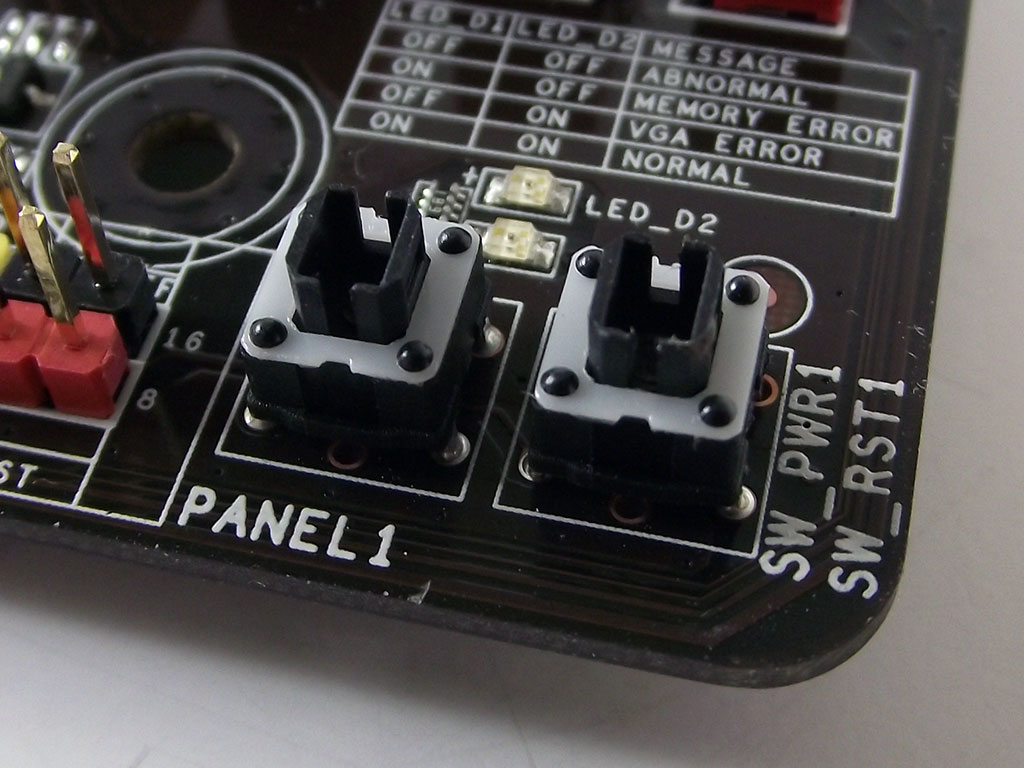
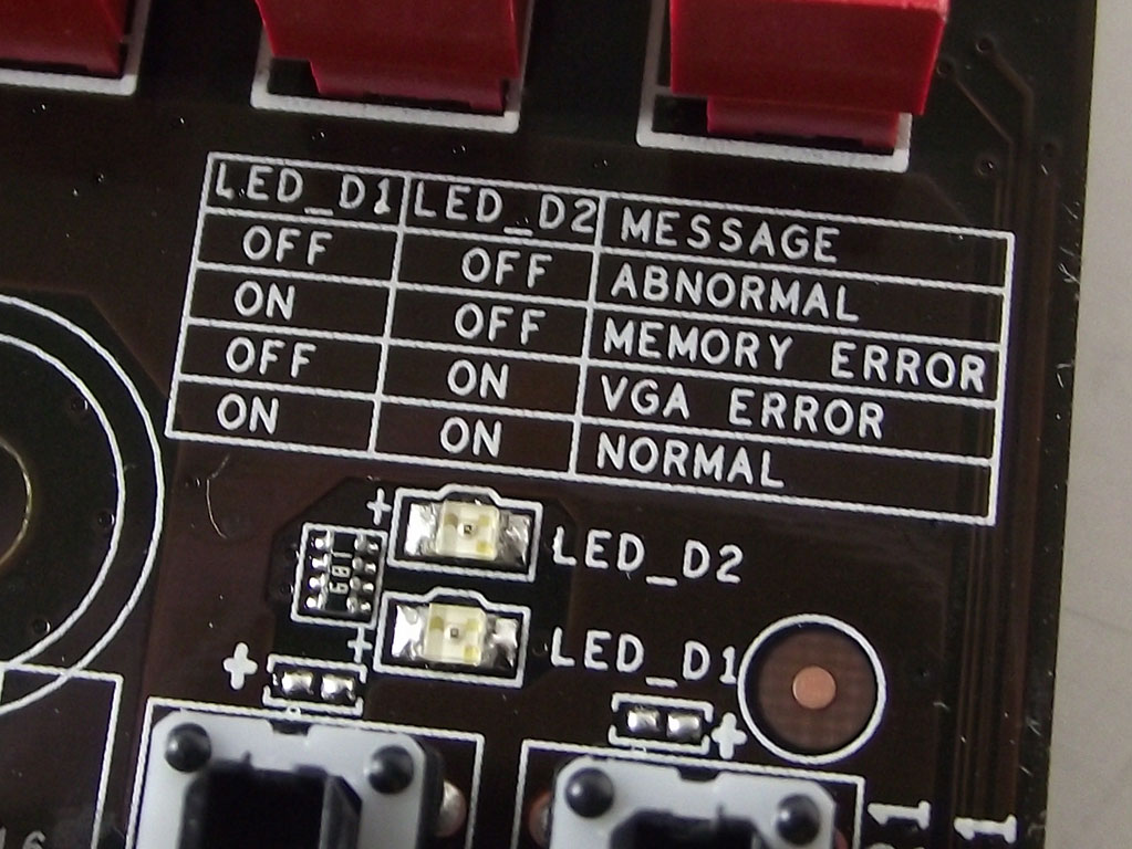
To get things booted up, Biostar has included both POWER and RESET switches on the bottom right edge of the board, with a small dual LED-based POST reader, to troubleshoot boot problems, located right above the switches, as seen in the images above. Similar in function to what is offered on other products, the LEDs will light up in a pre-specified order, and Biostar has even had the foresight to include a diagram to decipher what the lights show right next to the POST display, making understanding of its simple display quick and easy, without even having to look at the manual.
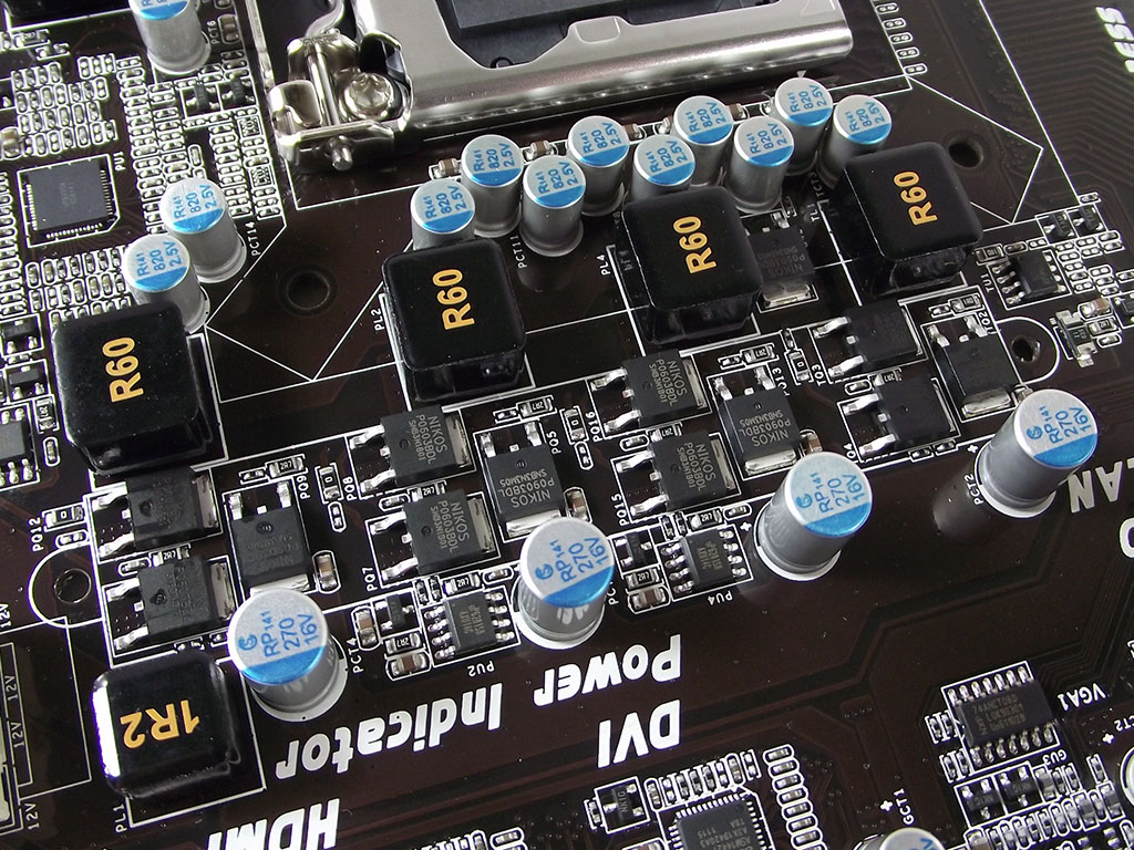
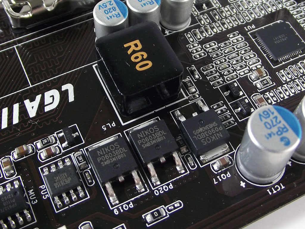
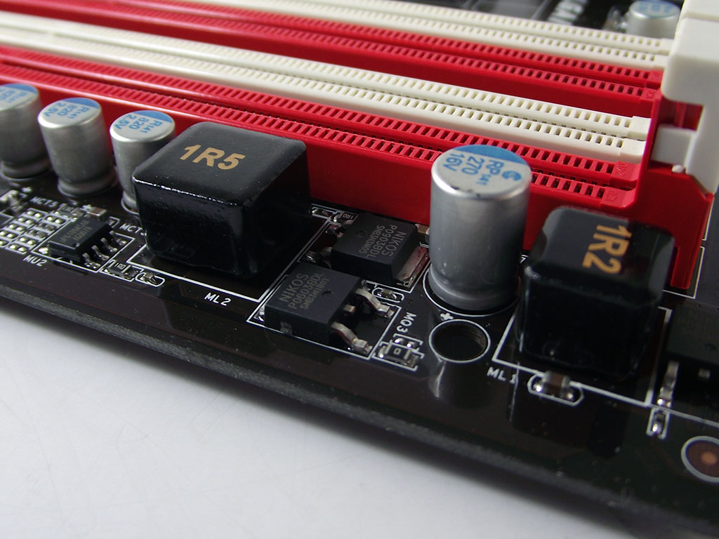
The TZ68A+'s VRM is a 4+1 phase design, with four phases dedicated to the CPU and System Agent power supply, and one for the onboard video portion. Each is a fairly standard hi/low tri-MOSFET configuration, using an inexpensive, yet efficient series of components. The DIMM VRM is a single-phase design, very similar to the CPU VRM, yet sporting a hi/low dual MOSFET design, and a different choke.
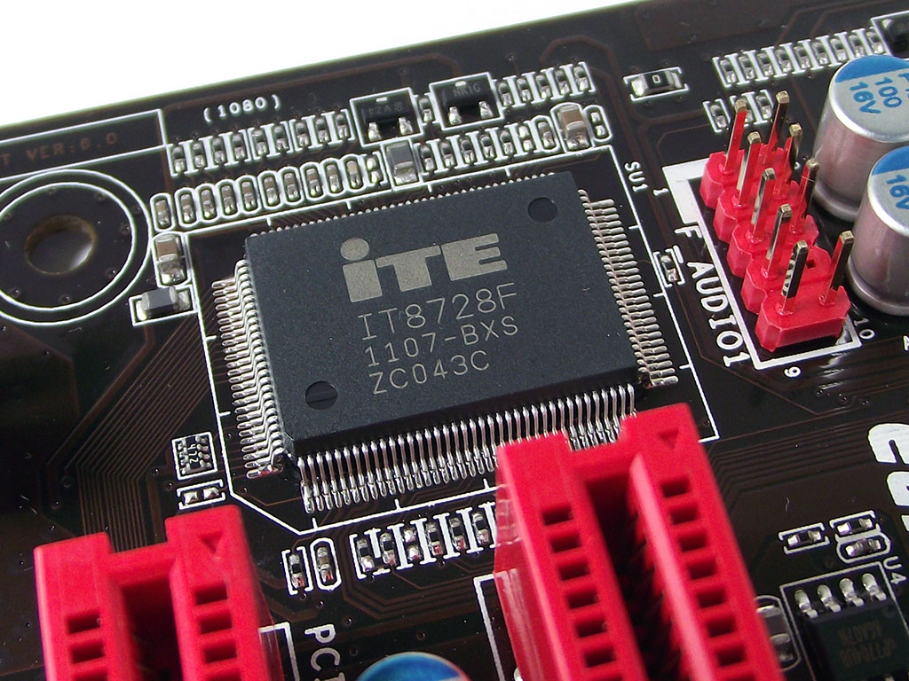
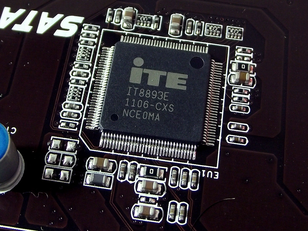
For Super I/O functionality, we find an ITE IT8728F, a part used quite often on other products. As is usual, this chip is responsible for fan control and sensor data monitoring. The ITE IT8893E PCIe-to-PCI bridge chip is another commonly seen part, one which we find to run a bit warm when not in use, but is more than capable.
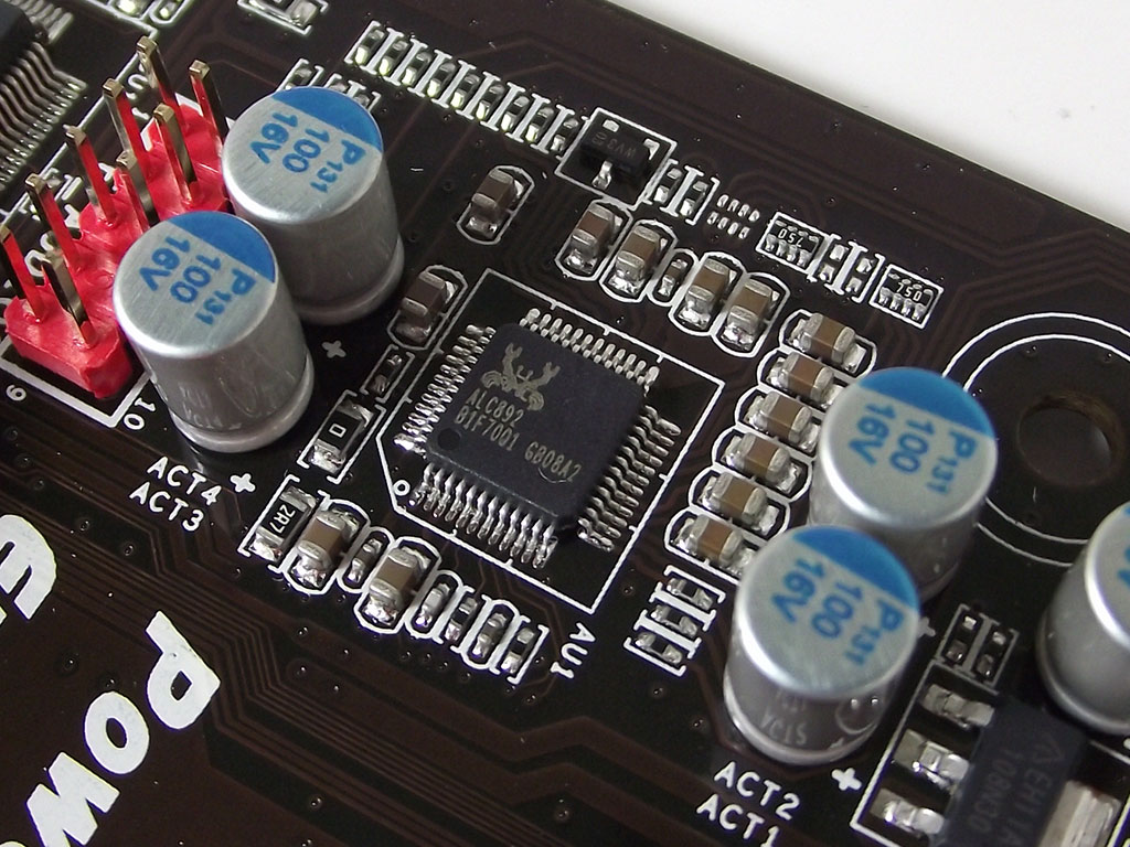
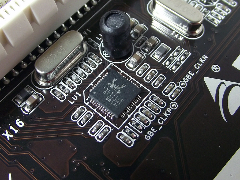
The included Realtek ALC892 HD codec supports 7.1+2 audio, and meets Microsoft's WLP3.x audio requirements. Using DACs that output a 97 db SNR, and ADCs with a 90 db SNR, it supports 44.1k/48k/96k/192 kHz sampling at 16-, 20- and 24-bit, including full support for HD audio formats featuring Content Protection, providing supporting software is used. It is also DirectSound 3D compatible, so no area of usage or functionality is overlooked. Biostar has also sourced the LAN controller for the Biostar TZ68A+ from Realtek; a utterly common RTL8111E PCIe part, located near the board's middle, just between the dual PCIe x16 slots.
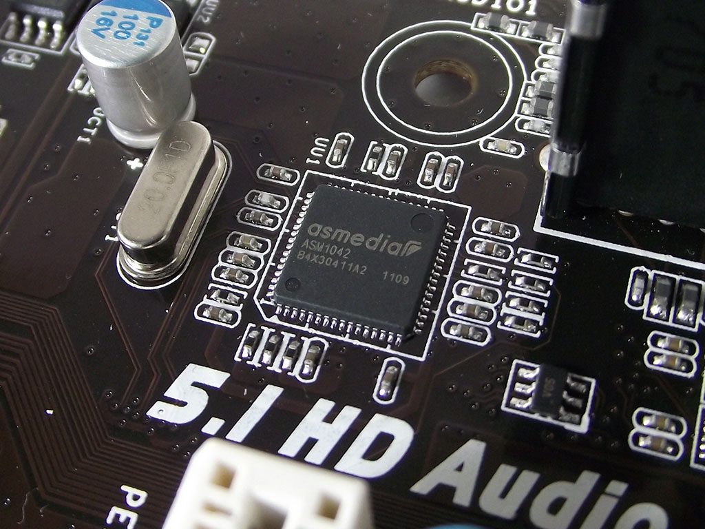
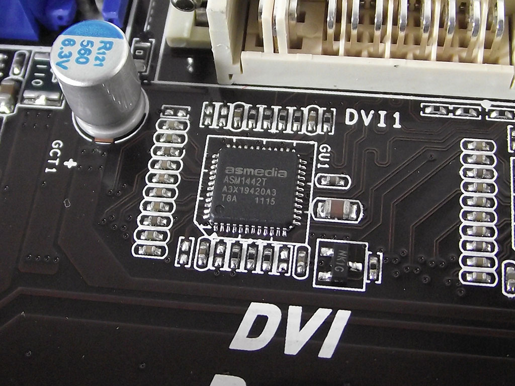
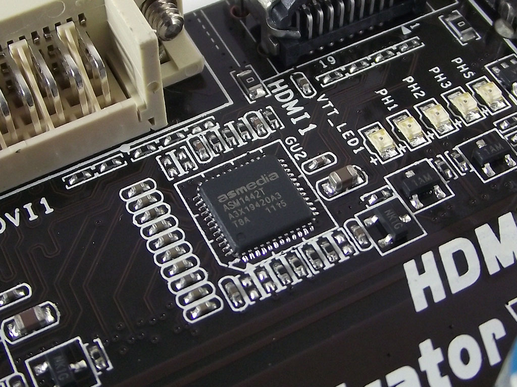
For USB 3.0 support, we find an Asmedia AS1042 PCIe-based controller, located just below the rear I/O assembly. While these controllers are not as familiar as the NEC/Renesas controller, which is far more common, we have found Asmedia controllers to be used on many recently-released products, although with very varied performance results. We also find two other Asmedia components on the TZ68A+, a set of two TMDS transmitters that allows users to use any of the two included onboard video outputs simultaneously.
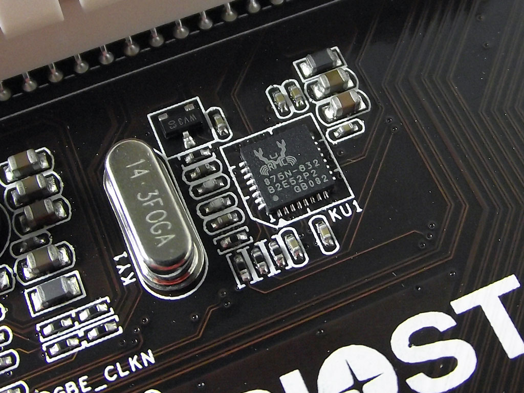
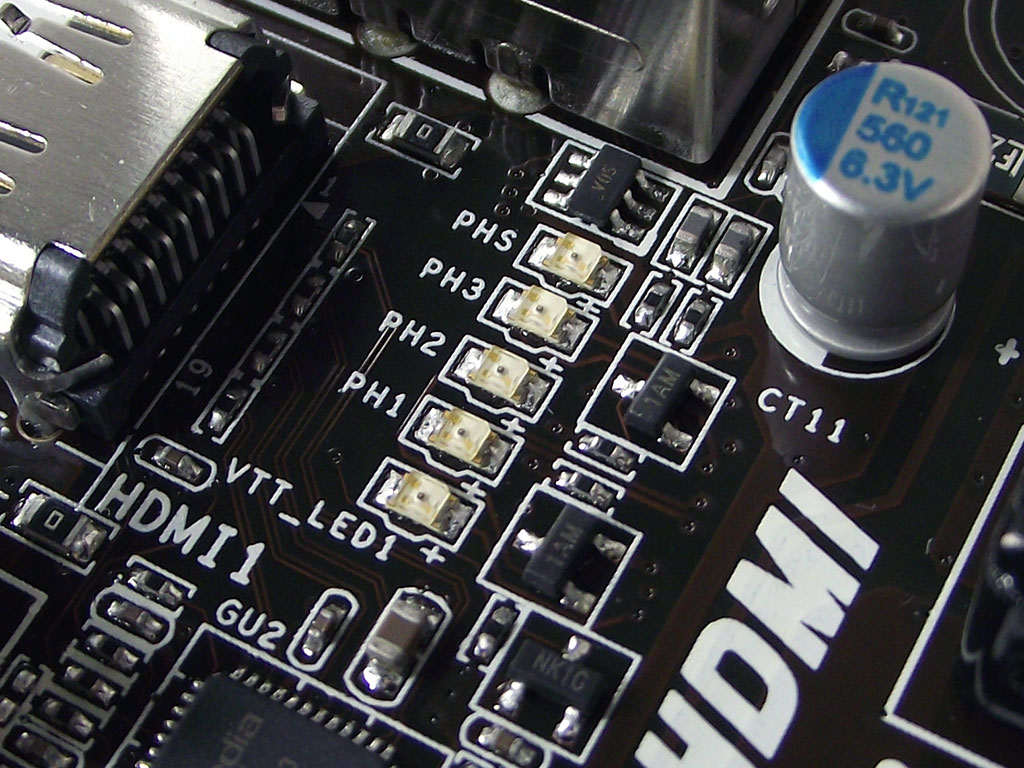
The final two onboard components are two not commonly seen; a Realtek clock generator, and the VRM phase load indicator. The Realtek clockgen is very rare, such that there is very little info about it to be found on the Internet, and no listing is to be found on the Realtek website. The VRM phase LEDs diverge from the norm a fair bit too, as rather than turning on and off as the phases are enabled or disabled, they simply increase their light intensity as the VRM is loaded, or lessen in intensity as load is decreased. With a few tweaks to the BIOS, the LEDs will show dynamic loading to each phase, but unlike other products, enabling such function does involve changing settings to P-States and a couple of other things, rather than a simple single BIOS item like on other products.
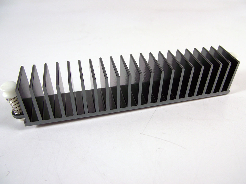

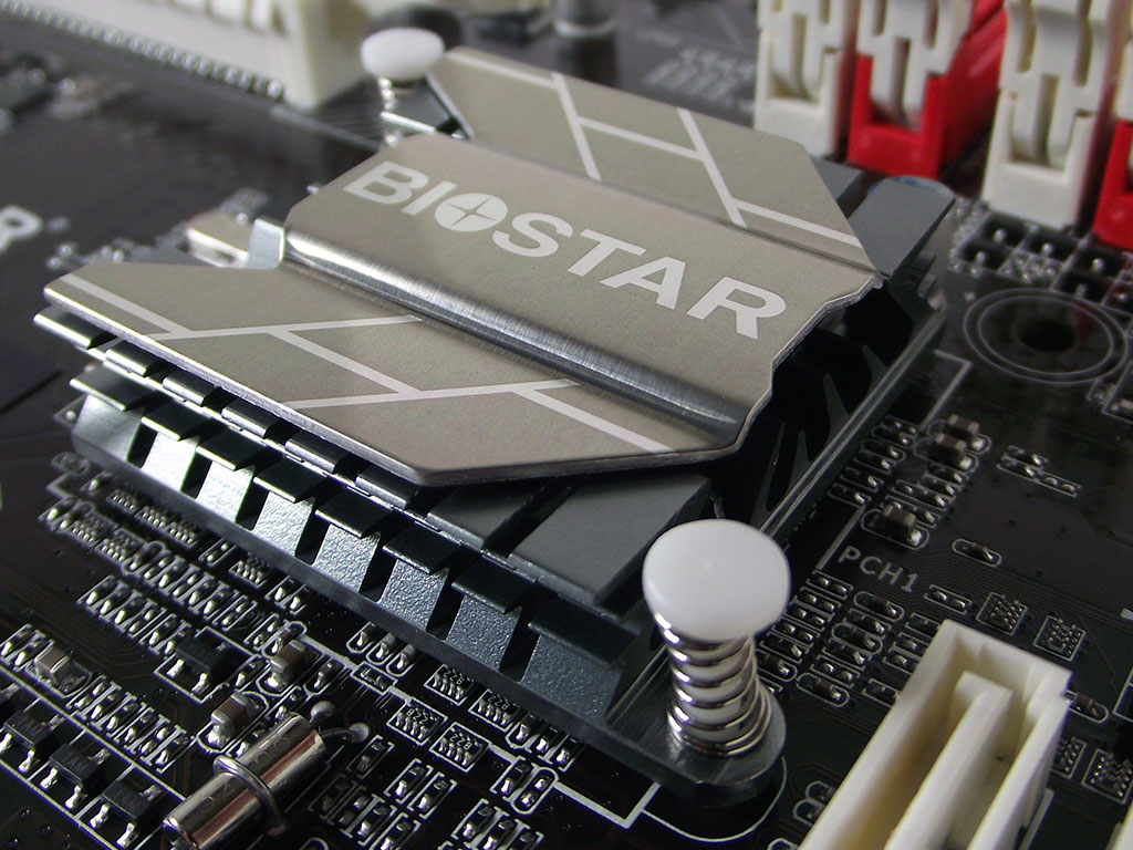
For cooling, Biostar has equipped the TZ68A+ with several aluminum passive heatsinks, which you can see in the pictures above. The VRM heatsink is quite light, and has a very low profile that ensures compatibility with the majority of aftermarket heatsinks. As we have found on other Intel SKT1155 motherboards, the VRM cooler’s contact with the actual VRM components is not perfect; near the middle we can find no indicator that the heatsink is even touching the VRM parts. The southbridge cooler employed on the TZ68A+, although not totally obvious in this picture, features many protruding fins under the vanity plate, to increase overall surface area. Through our testing, it did prove to be more than adequate, even with dual VGAs installed.
Feb 8th, 2025 10:01 EST
change timezone
Latest GPU Drivers
New Forum Posts
- Post your Monster Hunter Wilds benchmark scores (76)
- TPU's Rosetta Milestones and Daily Pie Thread (2182)
- Folding Pie and Milestones!! (9366)
- What's your latest tech purchase? (23110)
- RTX 2080 Super with TCL 55R635 causes flashes of purple on screen in RGB mode (3)
- The TPU UK Clubhouse (25689)
- Help choosing a GPU (8)
- Free Games Thread (4434)
- RTX 3060 i5-10400 32gb ram become very slow after cleaning (15)
- Asus crosshair x870e hero Q Led Issue (3)
Popular Reviews
- Kingdom Come Deliverance II Performance Benchmark Review - 35 GPUs Tested
- Spider-Man 2 Performance Benchmark Review - 35 GPUs Tested
- Formovie Cinema Edge 4K UST Laser Projector Review
- Kingdom Come: Deliverance 2 Handheld Performance Review
- Civilization VII Performance Benchmark Review - 35 GPUs Tested
- ASUS ROG Harpe Ace Extreme Review
- Corsair Frame 4000D Review
- NVIDIA GeForce RTX 5080 Founders Edition Review
- ASRock Phantom Gaming B850I Lightning Wi-Fi Review
- AMD Ryzen 7 9800X3D Review - The Best Gaming Processor
Controversial News Posts
- AMD Radeon 9070 XT Rumored to Outpace RTX 5070 Ti by Almost 15% (286)
- AMD is Taking Time with Radeon RX 9000 to Optimize Software and FSR 4 (256)
- AMD Denies Radeon RX 9070 XT $899 USD Starting Price Point Rumors (239)
- Edward Snowden Lashes Out at NVIDIA Over GeForce RTX 50 Pricing And Value (235)
- AMD Radeon RX 9070 XT & RX 9070 Custom Models In Stock at European Stores (226)
- New Leak Reveals NVIDIA RTX 5080 Is Slower Than RTX 4090 (215)
- AMD's Radeon RX 9070 Launch Faces Pricing Hurdles (175)
- AMD Radeon RX 9070 XT Tested in Cyberpunk 2077 and Black Myth: Wukong (169)