 1
1
Building a Keyboard 13: Wind Sin65 Custom Keyboard Kit
Switches »Wind Sin65: Closer Examination and Assembly
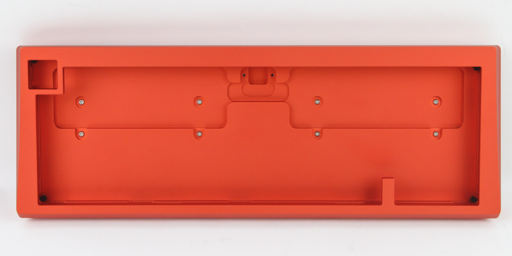
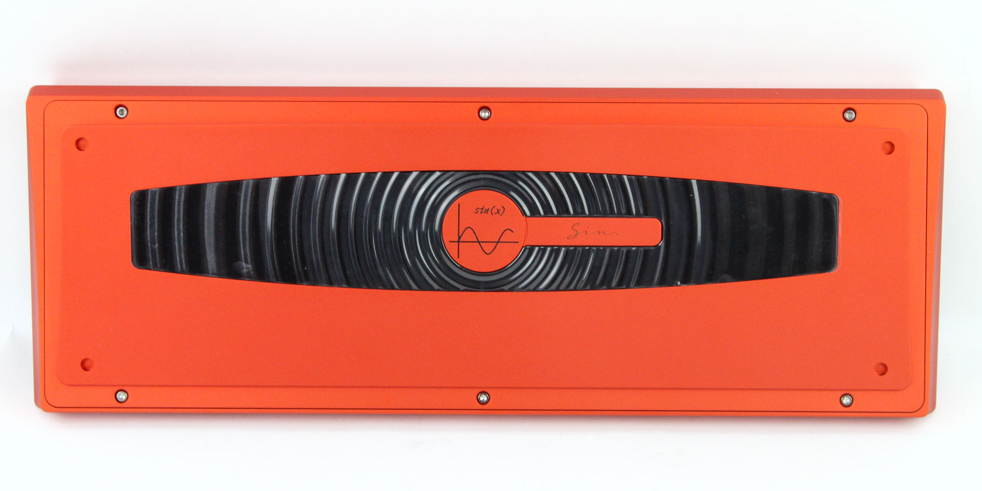
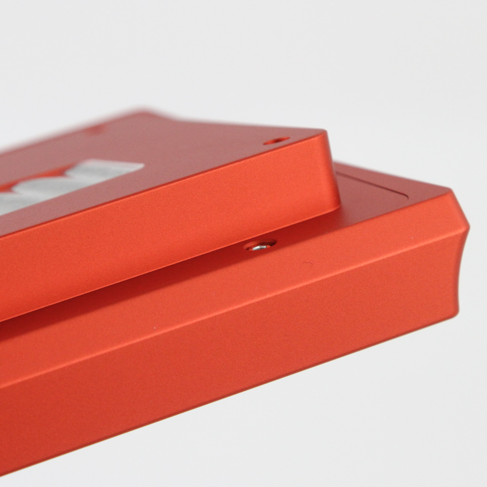
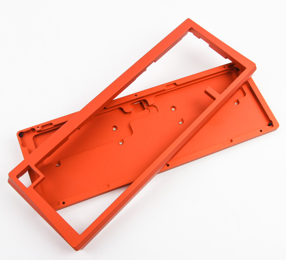
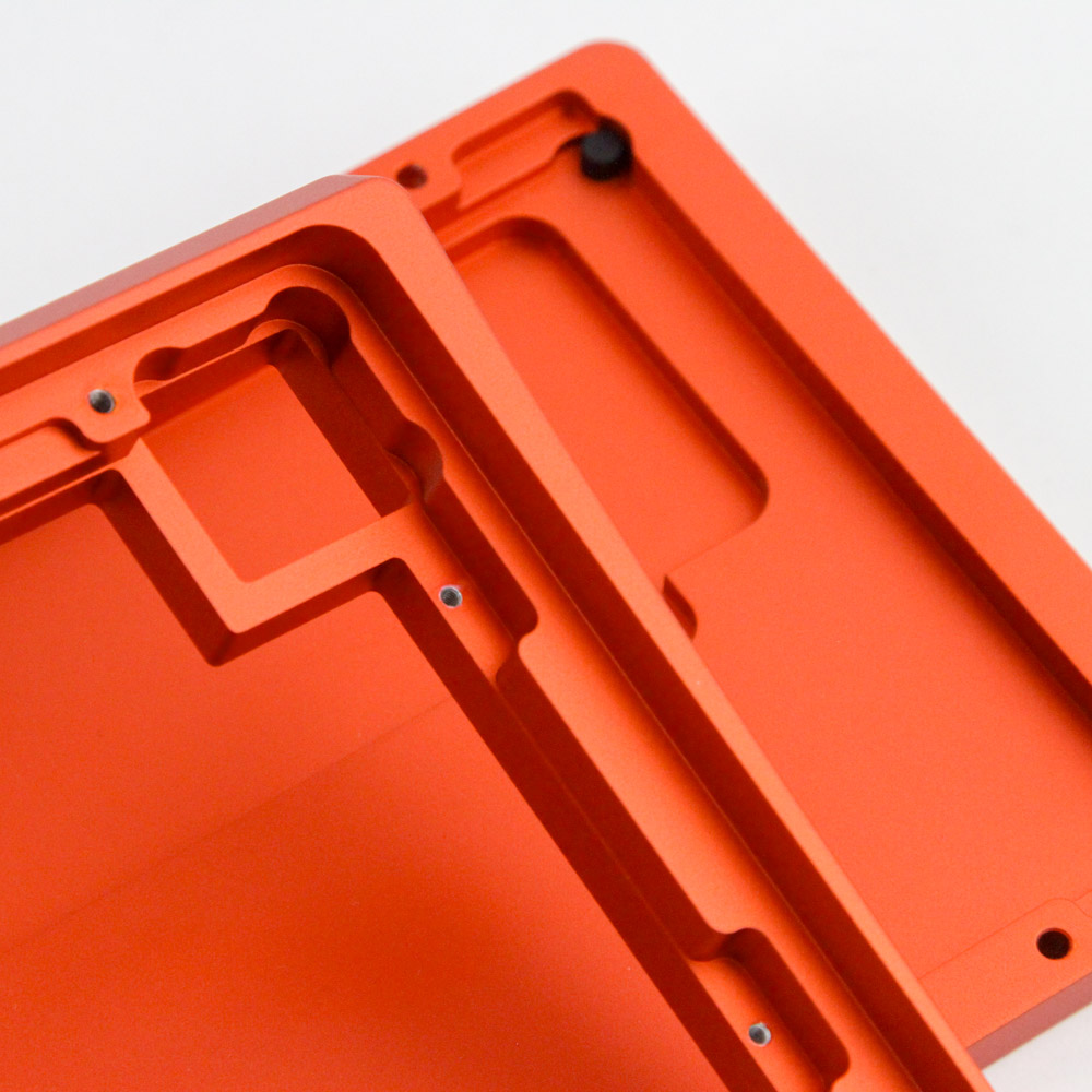
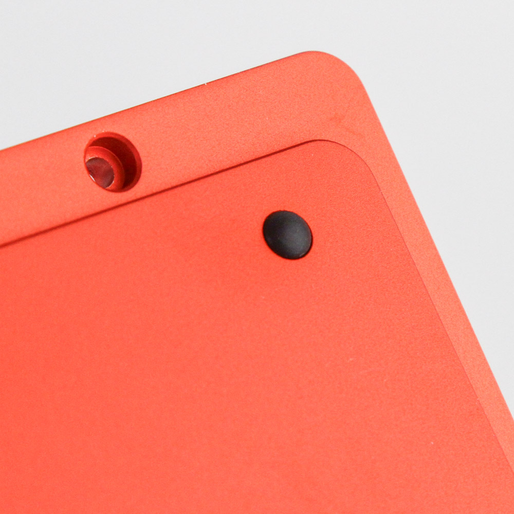
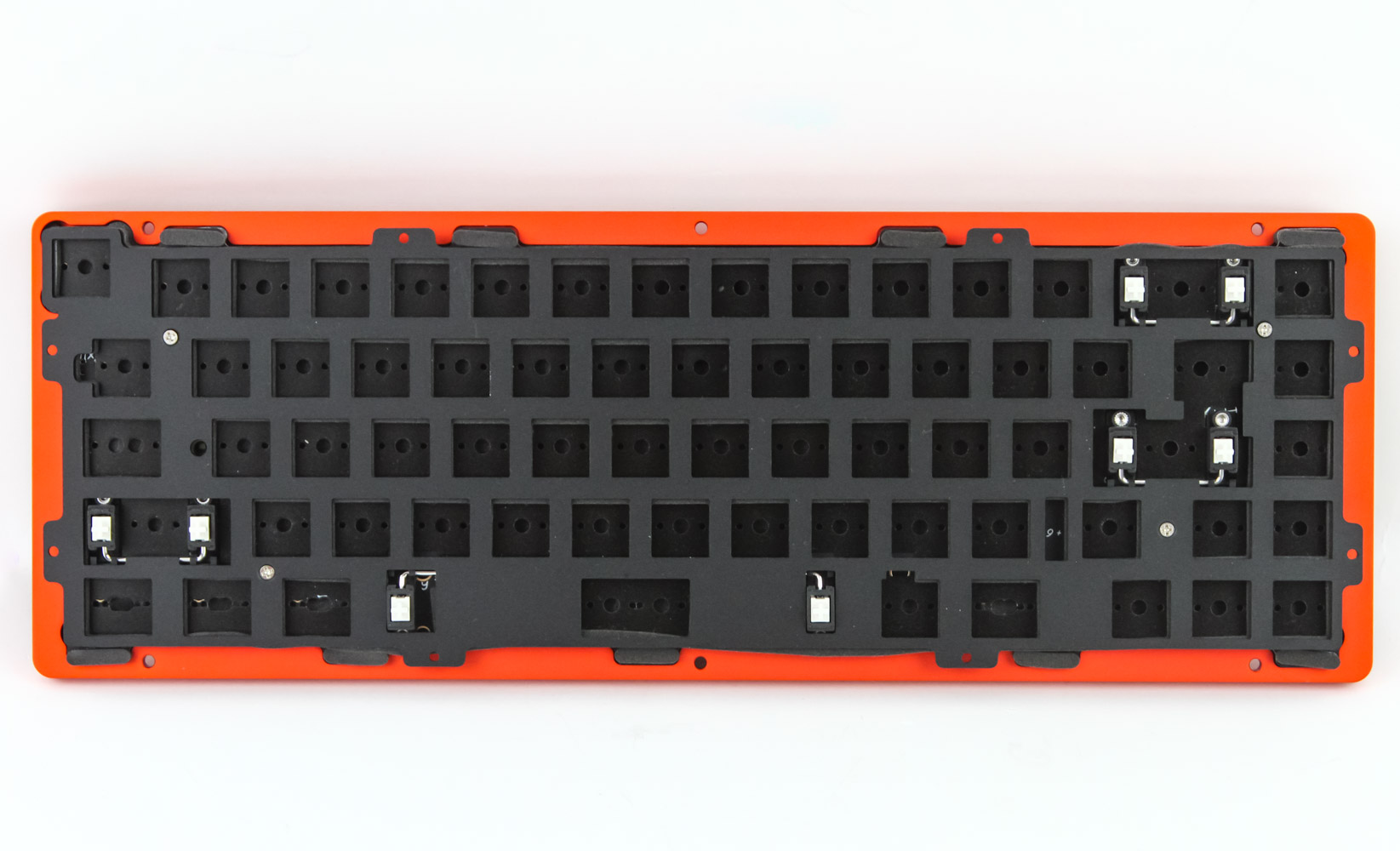
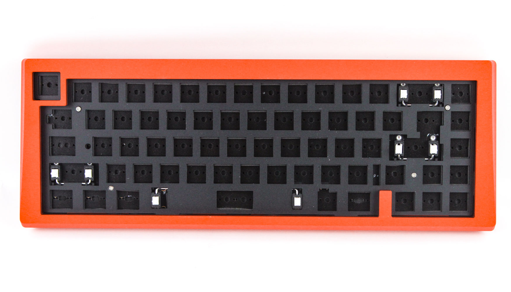
When asked about which kit version I'd like to examine, I took a look at the various options and thought that orange might be a nice change from the norm. This particular version happens to be anodized aluminium given a color closer to burnt orange than a brighter orange, although it does change hue slightly depending on the incident light making it hard to photograph consistently. No matter which version you go with, the kit measures in at 336 x 120 x 33.5 mm and the weight varies since you can have an aluminium kit or a polycarbonate one. The kit ships with just the top and bottom panels assembled although the retail units may have even these separate if the assembly manual is to go by. Note the separated Esc key though; this is a deliberate choice to reduce accidental hitting of Esc on this 65% form factor kit. On the back we see a pre-installed weight which also may ship separately packed in the final version. There is a sine curve in the middle with the product series alongside and I like the ripple-like pattern applied to the weight. There is a built-in 7° elevation integrated on the back given the absence of any keyboard feet and at this stage I decided to separate the two pieces to make the kit assembly much easier. It also gives a closer look at the internals and the flawless finish throughout. Begin by placing the four round rubber pads on the corners at the back as seen above. This will help raise the keyboard off your desk, thus preventing scratches and also adding friction in use.
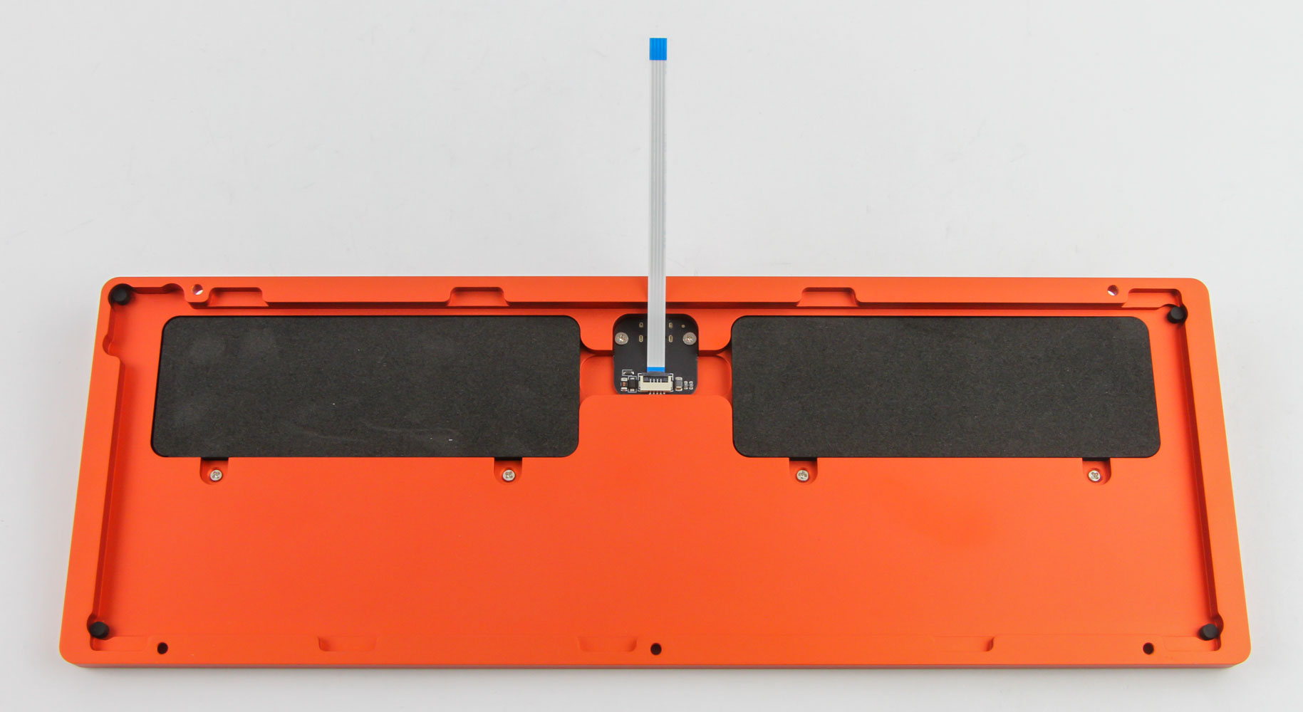
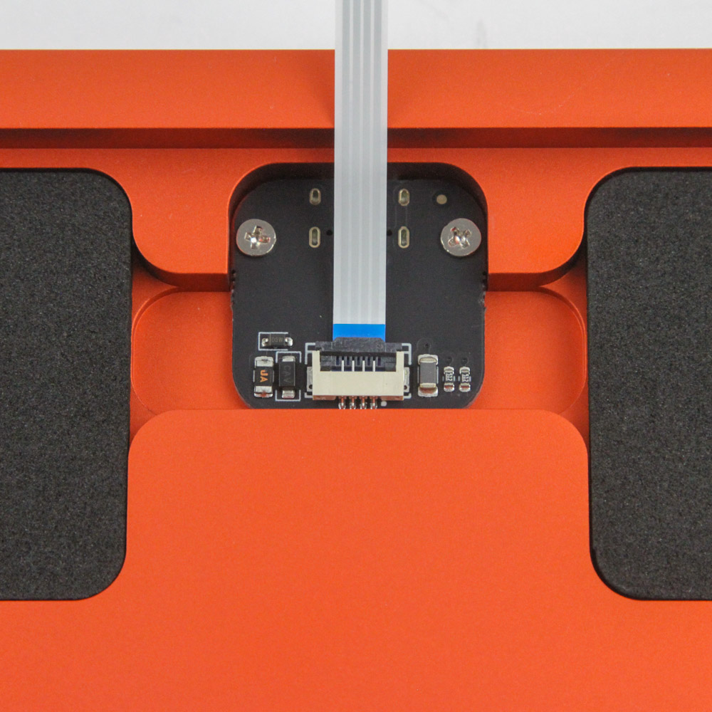
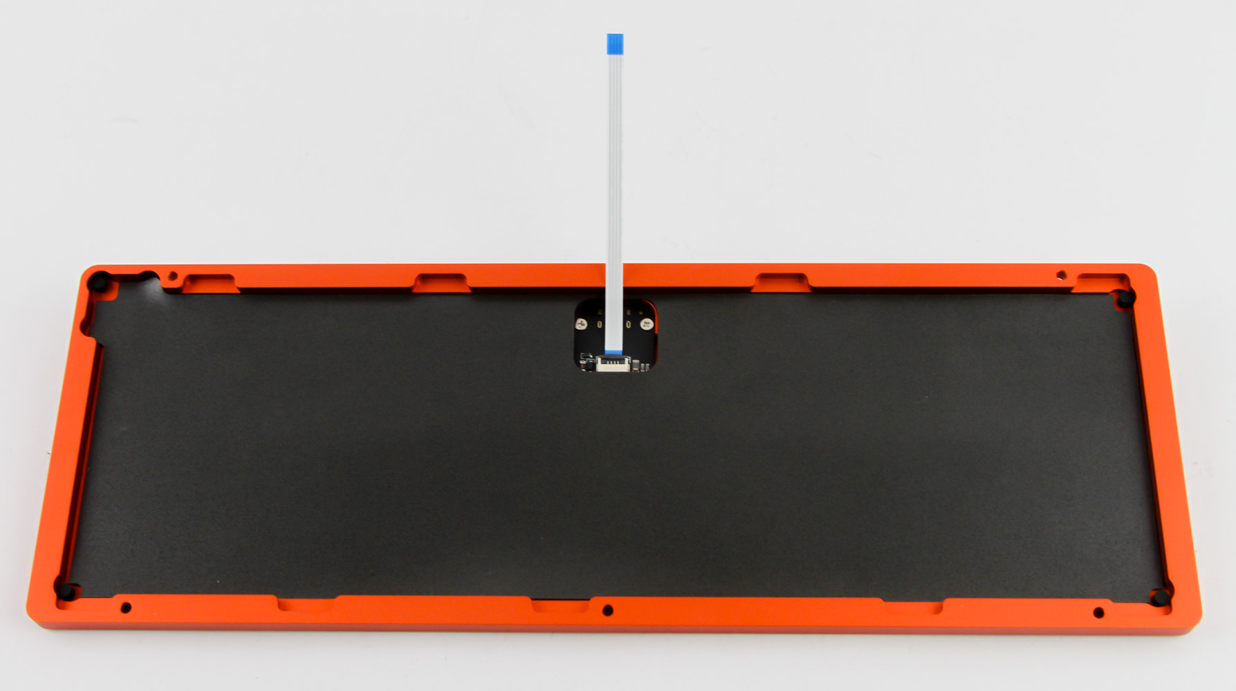
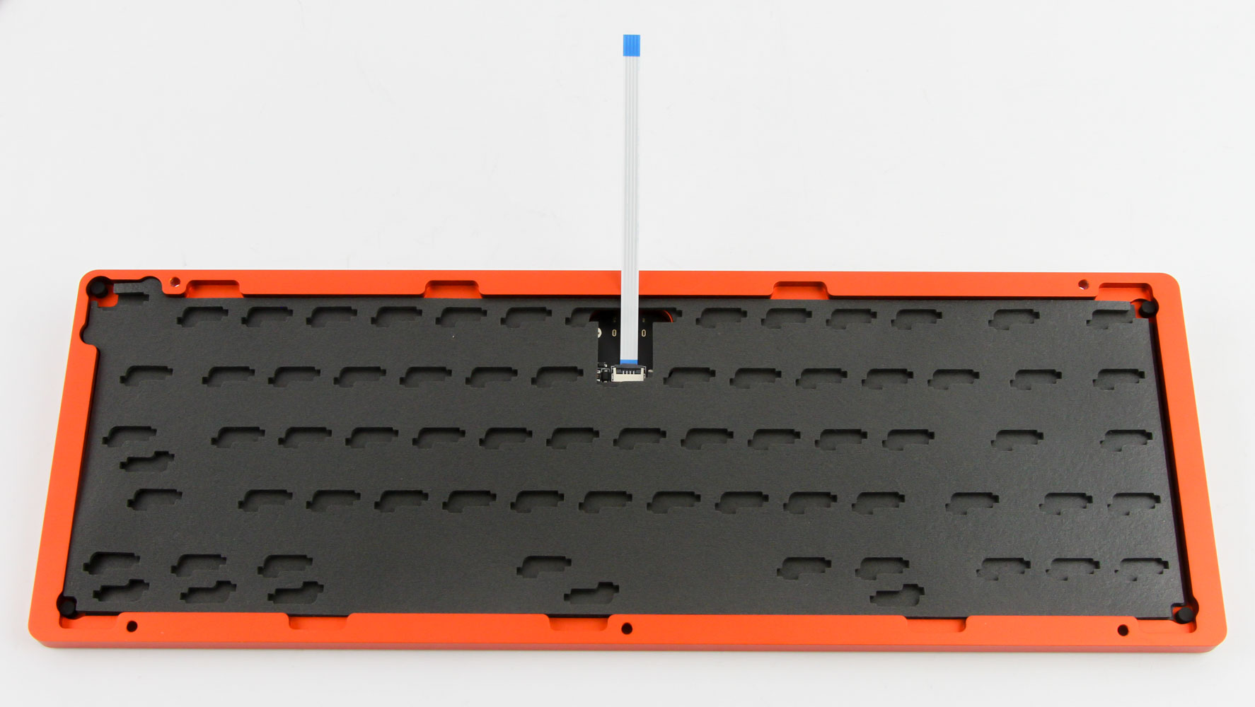
The wireless kit will have two separate batteries pre-installed in the recesses you see in the bottom case panel. This wired-only version thus comes with two "battery foam" pieces that you need to fit in those spaces so as to keep things as compact as possible. The next step is to install the Type-C daughterboard between the two foam pieces using the provided PCB board and screws. At this point, you can choose to install the provided 1 mm case foam or leave it out depending on how dampened you want the typing sound to be. I am going for a max damping and isolated keyboard here so I have added it along with the 2 mm thick hot-swap foam sheet as well. These have cutouts that go around the hot swap switch sockets snugly and there is now very little room left in the case. Wind Studio had pre-installed four round silicone stands in the corners too but the instructions suggest these may ship separately for you to do so yourself.
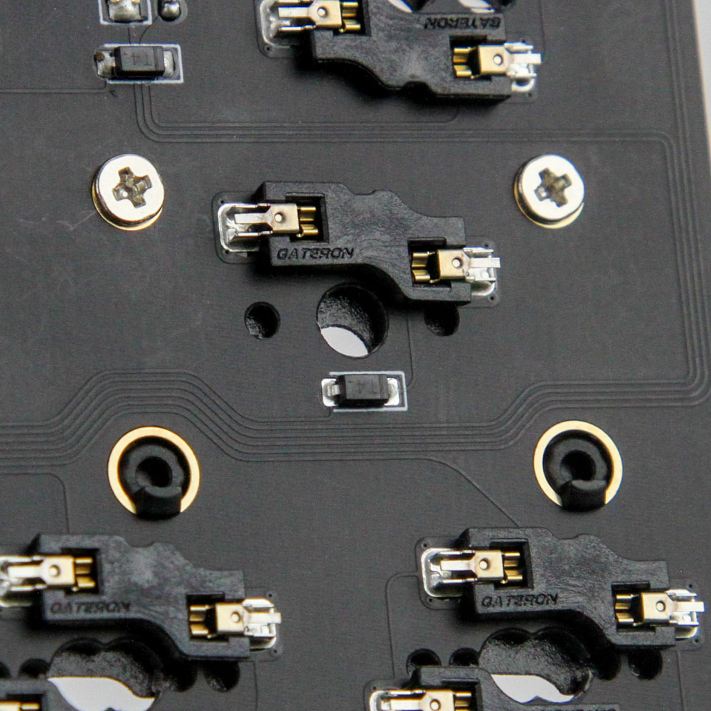
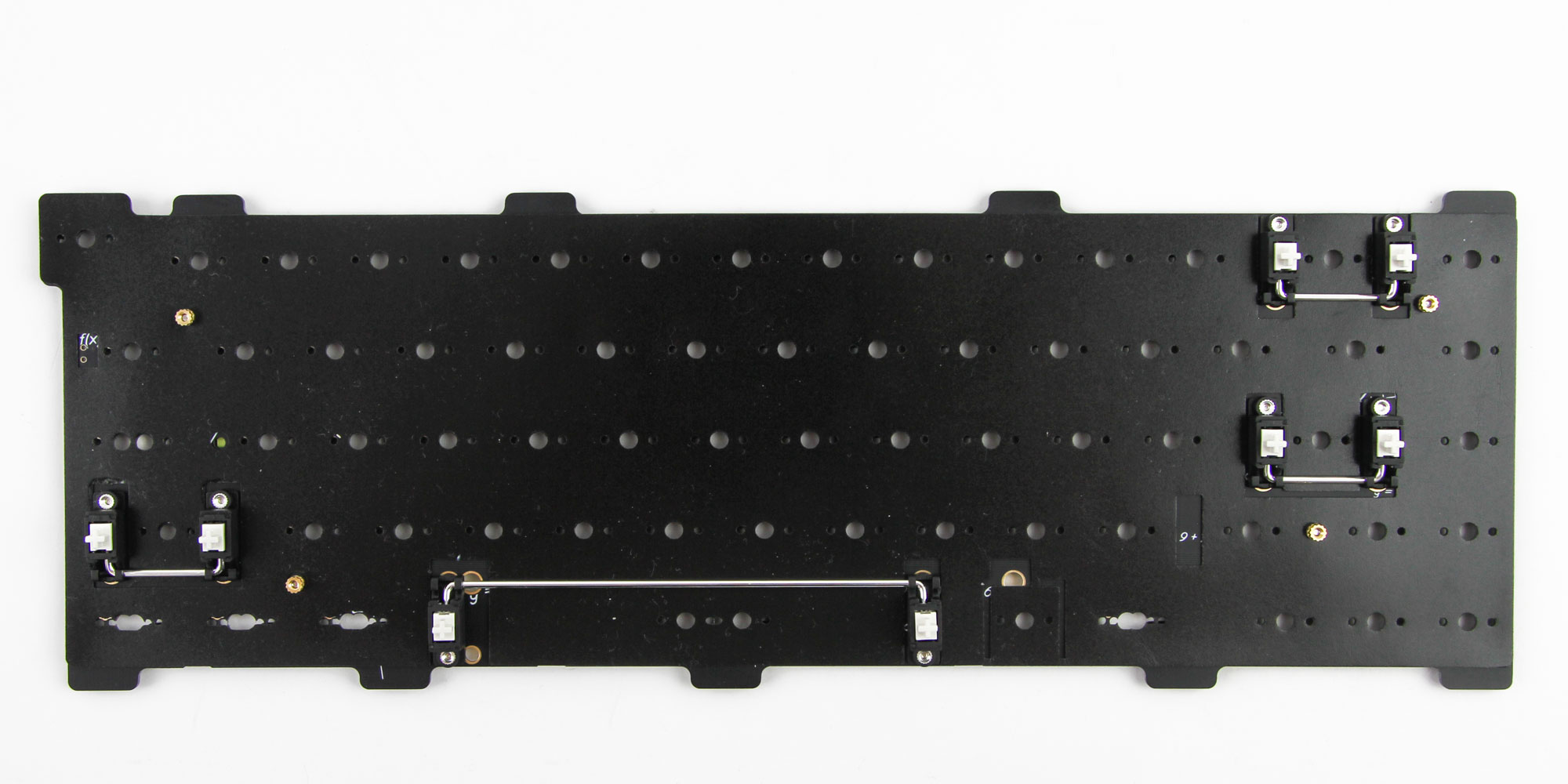
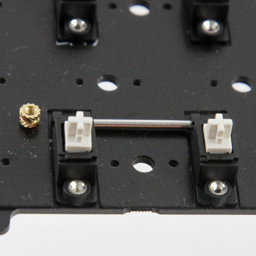
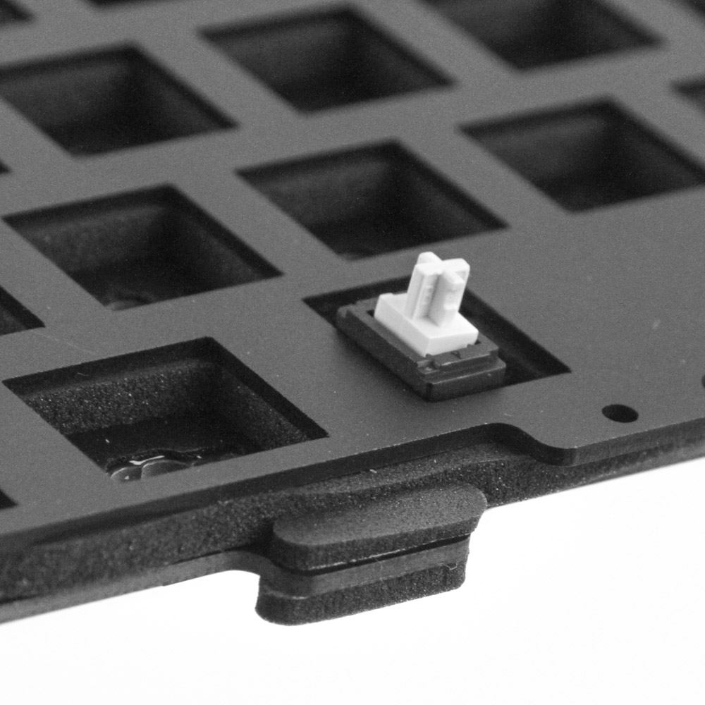
Time to assemble the plate/PCB section. Begin with inserting your choice of screw-in stabilizers for L.Shift, Space Bar, R.Shift, and Enter keys. I went with the ones Wind Studio had provided after applying a dab of lube at each end. Make sure you install them correctly—this can be easier if you first place the 0.5 mm IXPE sheet on top of the PCB on the front which will help align where the stabilizers are supposed to go. Screw the stabilizers from the back and then do the same for four brass standoffs—this can be fiddly—as seen above.
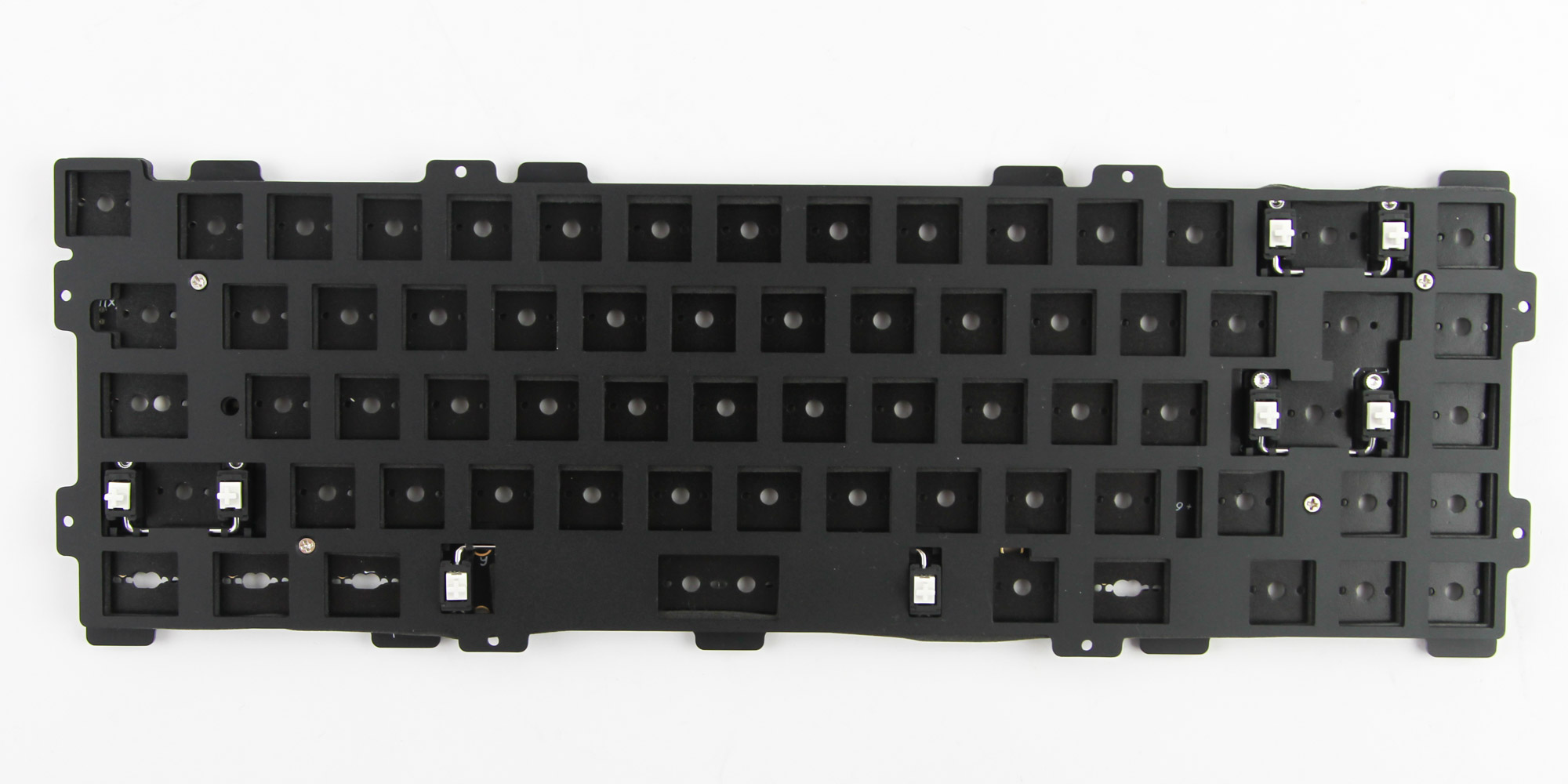
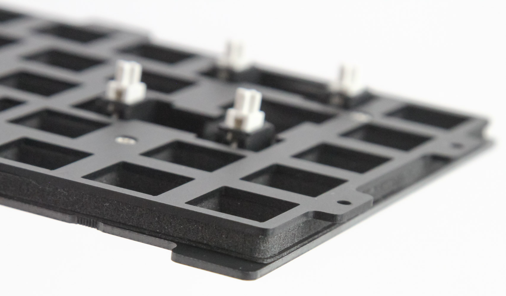
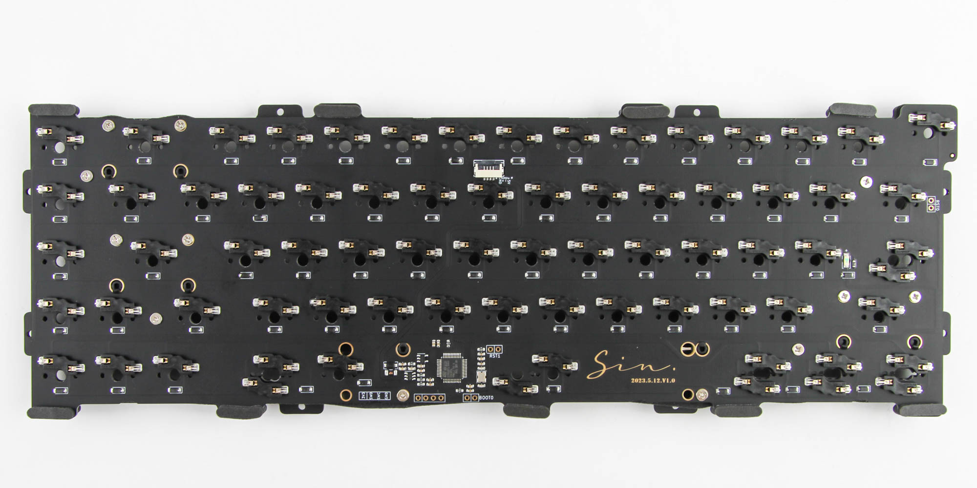
Those standoffs help screw the plate in place on the PCB. But here too you have a choice of adding either the 3.5 mm foam sheet, if you are going with the plate, or the thicker 5 mm foam sheet for a plate-less mount. Note that the plate-less mount option is only on the wired, soldered PCB so that is why I don't have the 5 mm foam sheet in the box either. I went with the 3.5 mm foam and the aluminium plate here; the polycarbonate plate can be slightly more flexible and I knew I wanted a gasket mount anyway. Indeed, this is why I then installed the foam gaskets around the PCB on either side. You can also go for a top mount here as Wind Studio provides the hardware to do so as well.
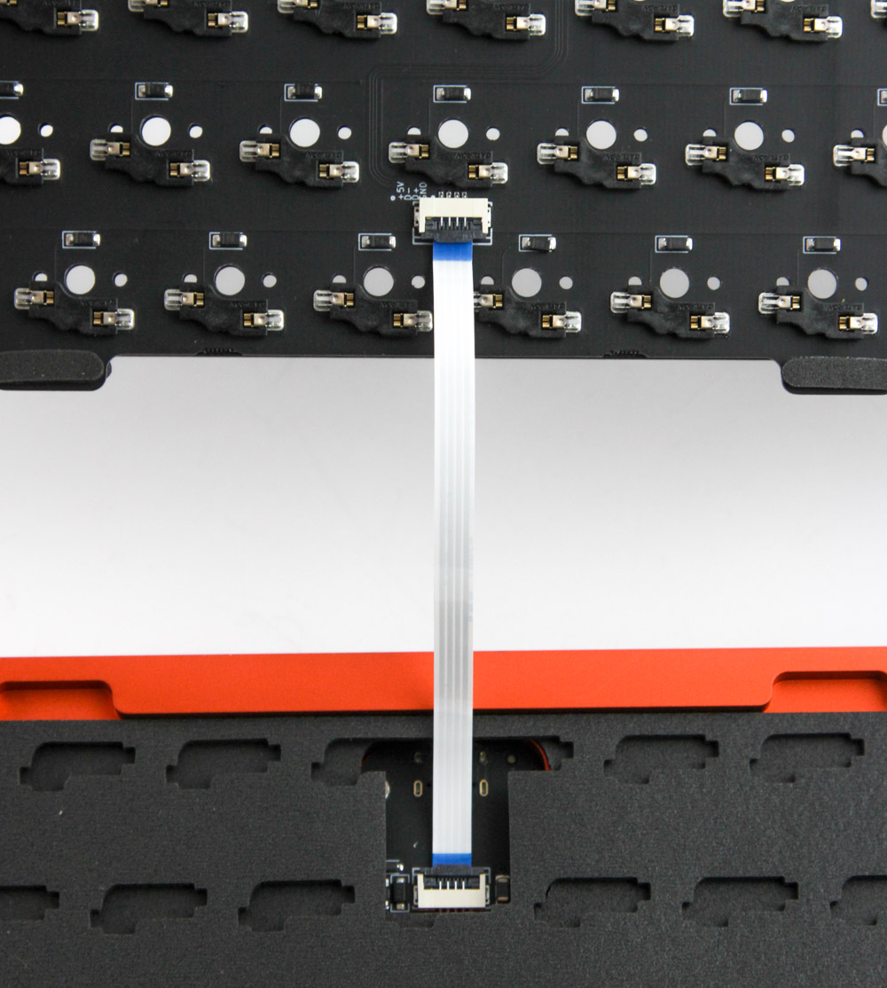
Once you have finalized the exact configuration of the bottom case panel as well as the plate/PCB section, it's time to connect the two and get the keyboard kit ready to go. The internal cable from the Type-C daughterboard goes into the connector on the PCB and is locked in place. Then flip over the plate/PCB section and—if you have gone for the gasket mount—simply orient it to have the gaskets be in the recesses in the bottom case panel before you put the top panel over and screw it all together from the back.
Mar 15th, 2025 20:56 EDT
change timezone
Latest GPU Drivers
New Forum Posts
- First Build Won't Boot - Yellow DRAM Light on ASUS Prime B550M-A WiFi II (5)
- I need a BIOS for the "Rx580 8gb" chip 215-0876406 (12)
- I can't find my chipset drivers in device manager, do I just not have them installed? I'm on an Intel CPU. (9)
- Adding 2 more sticks of DDR5 Ram 64gb for a total of 4 (8)
- *Severe micro stutters* cyberpunk 2077 Please help (58)
- What's your latest tech purchase? (23333)
- Post Your TIMESPY, PCMARK10 & FIRESTRIKE SCORES! (2019) (275)
- Last game you purchased? (723)
- DMM with PTC fuse (6)
- Astral 5080 Power limit (30)
Popular Reviews
- AMD Ryzen 9 9950X3D Review - Great for Gaming and Productivity
- Gigabyte X870E Aorus Pro Review
- Sapphire Radeon RX 9070 XT Nitro+ Review - Beating NVIDIA
- ASUS GeForce RTX 5090 TUF Review
- XFX Radeon RX 9070 XT Mercury OC Magnetic Air Review
- MSI GeForce RTX 5070 Gaming Trio OC Review
- VAXEE Zygen NP-01S V2 Wireless Review
- FSP MP7 Black Review
- ASUS Radeon RX 9070 TUF OC Review
- Dough Spectrum Black 32 Review
Controversial News Posts
- NVIDIA GeForce RTX 50 Cards Spotted with Missing ROPs, NVIDIA Confirms the Issue, Multiple Vendors Affected (513)
- AMD RDNA 4 and Radeon RX 9070 Series Unveiled: $549 & $599 (260)
- AMD Mentions Sub-$700 Pricing for Radeon RX 9070 GPU Series, Looks Like NV Minus $50 Again (249)
- NVIDIA Investigates GeForce RTX 50 Series "Blackwell" Black Screen and BSOD Issues (244)
- AMD Radeon RX 9070 and 9070 XT Official Performance Metrics Leaked, +42% 4K Performance Over Radeon RX 7900 GRE (195)
- AMD Radeon RX 9070-series Pricing Leaks Courtesy of MicroCenter (158)
- AMD Radeon RX 9070 XT Reportedly Outperforms RTX 5080 Through Undervolting (116)
- Microsoft Introduces Copilot for Gaming (107)