 2
2
Cherry MX Board 3.0 Review
Driver »Disassembly
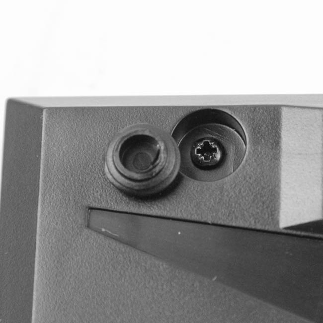


Disassembly of the Cherry MX Board 3.0 is extremely simple, provided you know where the screws are. There are five with a precision Phillips head, all hidden underneath the five flat surface plastic pieces at the top of the keyboard on the back. Use a thin, flat driver to pry them out and that should be that. Once done, use the same flat object to pry open the interlocking tabs holding the plastic case-panel pieces together. There are not very many of them, and they were easy enough to remove relative to most others. Once done, the top panel piece comes loose, but can not yet be removed.


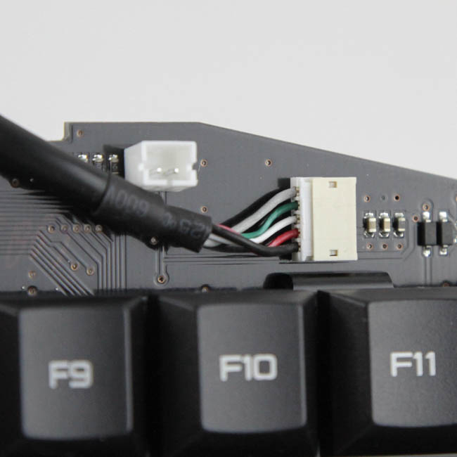

You need to dislodge the LED power connector that powers the LEDs under the Cherry logo in the top panel piece, and doing so helps separate it from the rest of the keyboard. Now, dislodge the internal USB connector and lift the PCB upward to separate the cable, PCB/plate, and bottom panel piece. We see that a stainless steel plate is used internally for structural integrity, and there is a matte black PCB with plate-mounted switches that have been soldered through the two.

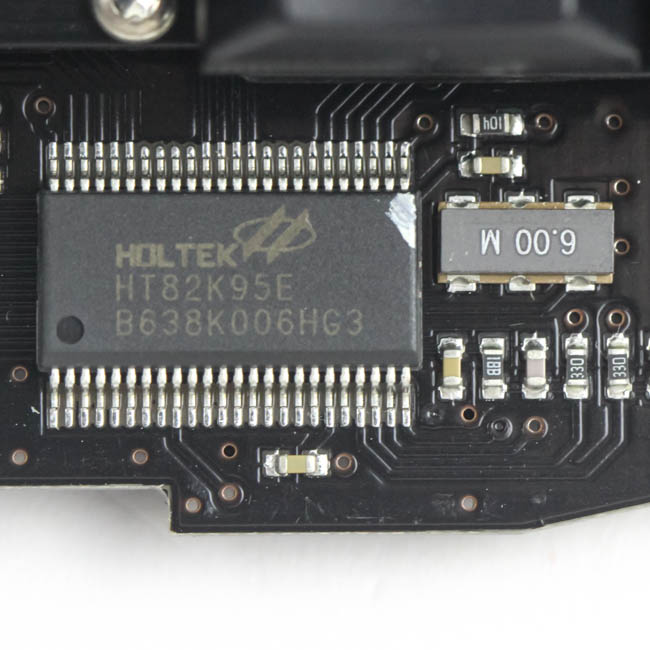
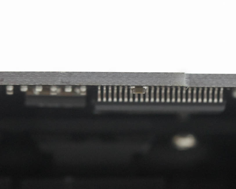
Solder quality is very good with no solder peaks at all, and with not very many LEDs to solder either, there are only the four solder points per switch in most places. The keyboard has a Holtek HT82K95E 8-bit USB microcontroller on the other side to control the functionality of the keyboard, on a multi-layered PCB.
Before we take a look at the driver, be advised that disassembly will void the warranty and that TechPowerUp is not liable for any damages incurred if you decided to go ahead and do so anyway.
Feb 28th, 2025 19:30 EST
change timezone
Latest GPU Drivers
New Forum Posts
- What is your comfortable price range for a graphics card? (49)
- It's happening again, melting 12v high pwr connectors (968)
- Amd rx570 sapphire nitro 8gb+ not detected (21)
- 9800X3D OC Limits? (17)
- Disabling MPO (MultiPlane Overlay) in 2025 (13)
- The TPU UK Clubhouse (25819)
- I5 10300H undervolting ,need to stop thermal throttle (7)
- MSI Vector 17 HX A14VIG "EDP OTHER" (18)
- Which model are running for code assistance? (8)
- [Feature request] Optional GFE Download (0)
Popular Reviews
- AMD Radeon RX 9070 Series Technical Deep Dive
- Montech HyperFlow Silent 360 Review
- Gigabyte X870 Aorus Elite WiFi 7 Review
- ASUS GeForce RTX 5070 Ti TUF OC Review
- ASUS ROG Harpe Ace Mini Review
- be quiet! Pure Base 501 DX Review
- Corsair Xeneon 34WQHD240-C Review - Pretty In White
- AMD Ryzen 7 9800X3D Review - The Best Gaming Processor
- Montech TITAN PLA 1000 W Review
- MSI GeForce RTX 5070 Ti Vanguard SOC Review
Controversial News Posts
- NVIDIA GeForce RTX 50 Cards Spotted with Missing ROPs, NVIDIA Confirms the Issue, Multiple Vendors Affected (498)
- AMD Plans Aggressive Price Competition with Radeon RX 9000 Series (274)
- AMD Radeon RX 9070 and 9070 XT Listed On Amazon - One Buyer Snags a Unit (255)
- AMD Mentions Sub-$700 Pricing for Radeon RX 9070 GPU Series, Looks Like NV Minus $50 Again (248)
- NVIDIA Investigates GeForce RTX 50 Series "Blackwell" Black Screen and BSOD Issues (244)
- Edward Snowden Lashes Out at NVIDIA Over GeForce RTX 50 Pricing And Value (243)
- AMD Radeon RX 9070 and 9070 XT Official Performance Metrics Leaked, +42% 4K Performance Over Radeon RX 7900 GRE (191)
- AMD RDNA 4 and Radeon RX 9070 Series Unveiled: $549 & $599 (180)