 8
8
Cooler Master V Series 1000 W Review
Ripple Measurements »Advanced Transient Response Tests
In these tests, we monitor the response of the PSU in two different scenarios. First, a transient load (10 A at +12V, 5 A at 5V, 5 A at 3.3V, and 0.5 A at 5VSB) is applied to the PSU for 200 ms while the latter is working at a 20% load state. In the second scenario, the PSU, while working at 50% load, is hit by the same transient load. In both tests, we measure the voltage drops that the transient load causes using our oscilloscope. The voltages should remain within the regulation limits defined by the ATX specification. We must stress here that the above tests are crucial since they simulate transient loads that a PSU is very likely to handle (e.g., booting a RAID array, an instant 100% load of CPU/VGAs, etc.). We call these tests "Advanced Transient Response Tests", and they are designed to be very tough to master, especially for PSUs with capacities lower than 500 W.| Advanced Transient Response 20% | ||||
|---|---|---|---|---|
| Voltage | Before | After | Change | Pass/Fail |
| 12 V | 12.106V | 12.033V | 0.60% | Pass |
| 5 V | 5.018V | 4.953V | 1.30% | Pass |
| 3.3 V | 3.338V | 3.257V | 2.43% | Pass |
| 5VSB | 5.049V | 4.999V | 0.99% | Pass |
| Advanced Transient Response 50% | ||||
|---|---|---|---|---|
| Voltage | Before | After | Change | Pass/Fail |
| 12 V | 12.075V | 11.992V | 0.69% | Pass |
| 5 V | 5.021V | 4.965V | 1.12% | Pass |
| 3.3 V | 3.337V | 3.255V | 2.46% | Pass |
| 5VSB | 5.034V | 4.992V | 0.83% | Pass |
The response of all rails to dynamic loads is excellent! The +12V and 5VSB rails stayed below 1% on both tests, while the 5V and 3.3V rails kept their deviations within 2% and 3% respectively.
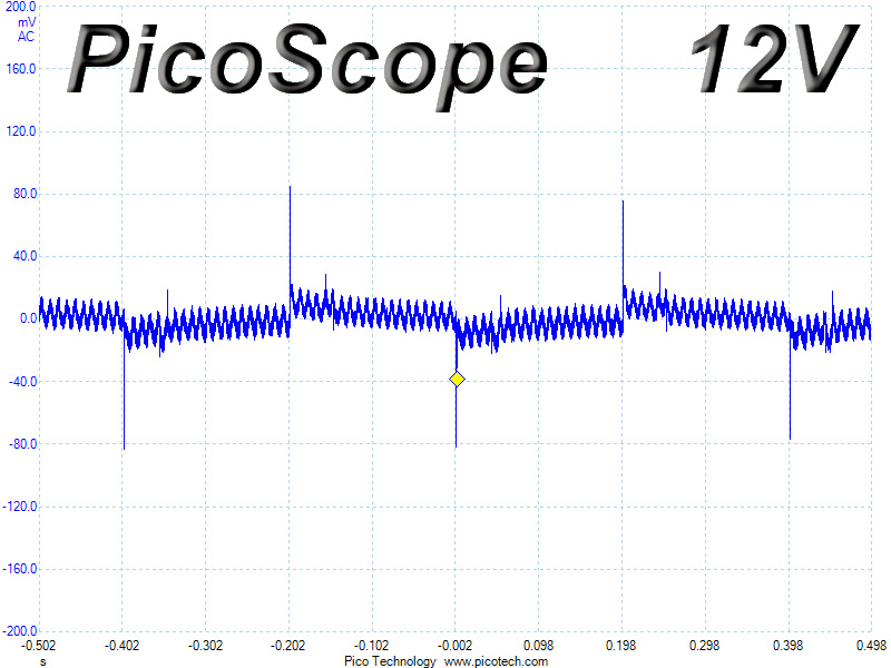
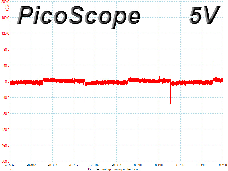
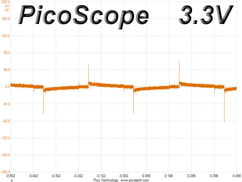
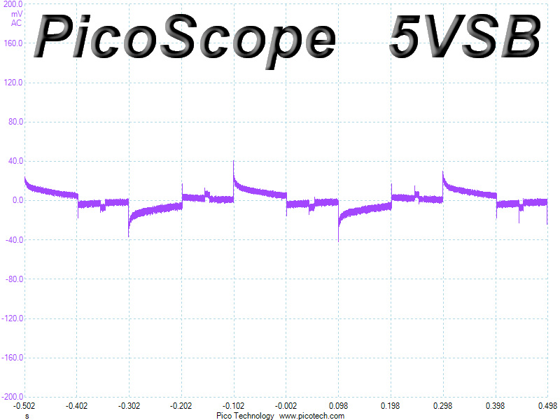
Below, you will find the oscilloscope screenshots we took during Advanced Transient Response Testing.
Transient Response at 20% Load
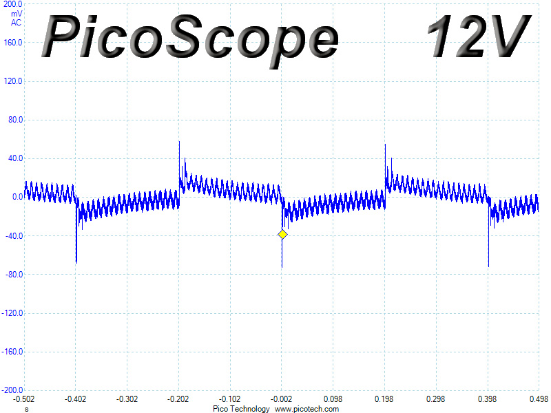
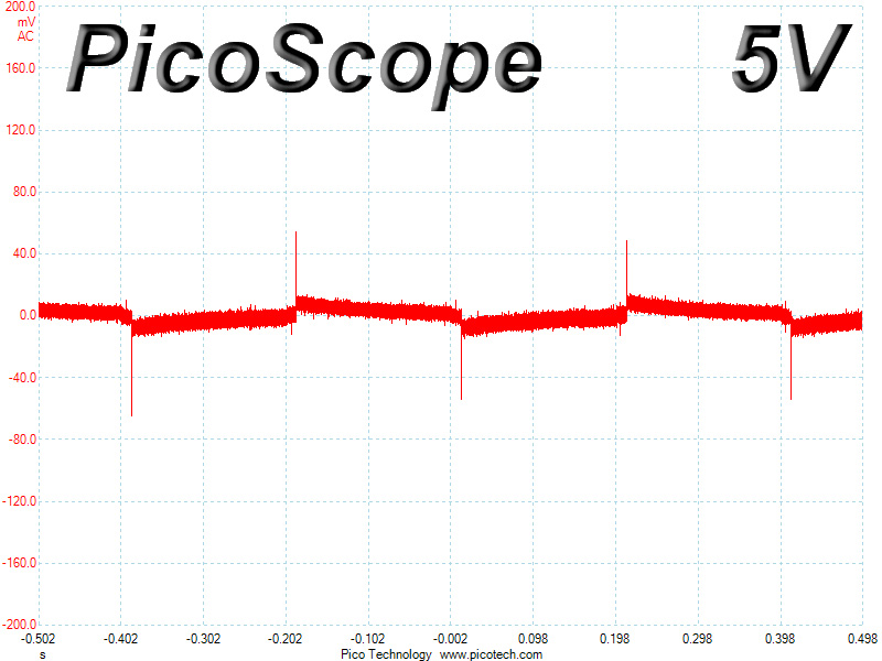
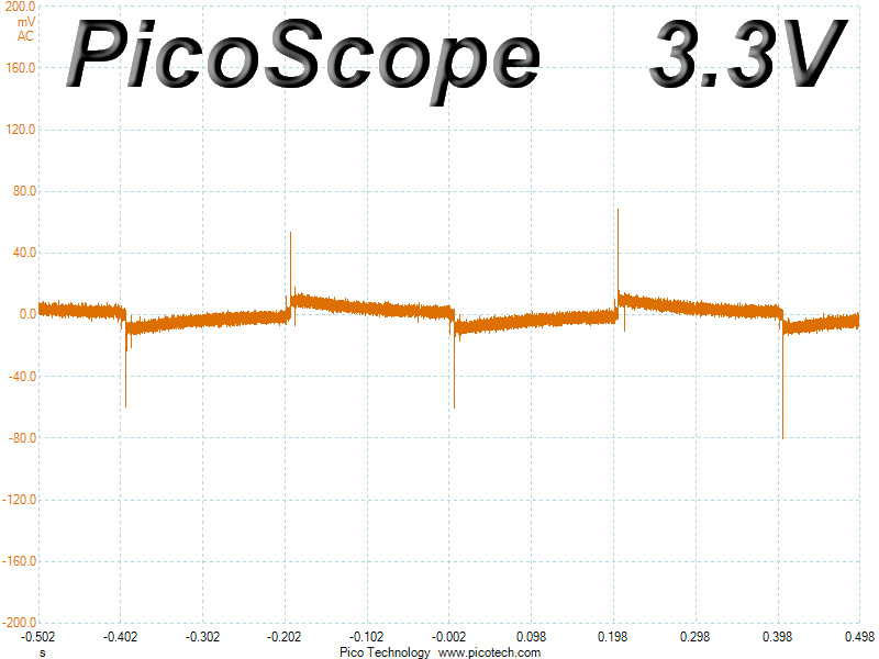
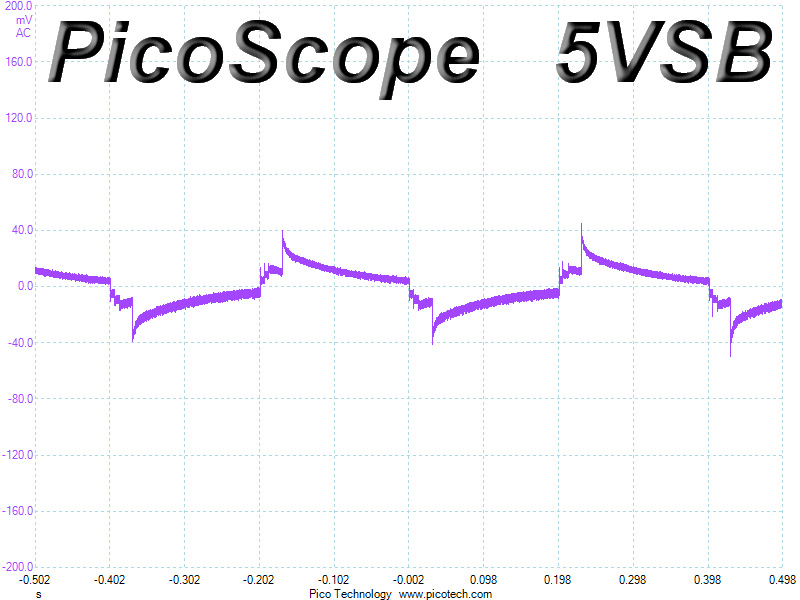
Transient Response at 50% Load
Turn-On Transient Tests
We measure the response of the PSU in simpler scenarios of transient loads—during the power-on phase of the PSU—in the next set of tests. In the first test, we turn the PSU off, dial the maximum current that the 5VSB can output, and then switch on the PSU. In the second test, we dial the maximum load that +12V can handle and start the PSU while the PSU is in standby mode. In the last test, while the PSU is completely switched off (we cut off power or switch off the PSU's on/off switch), we dial the maximum load that the +12V rail can handle before switching the PSU on from the loader and restoring power. The ATX specification states that recorded spikes on all rails should not exceed 10% of their nominal values (e.g., +10% for 12V is 13.2V and 5.5V for 5V).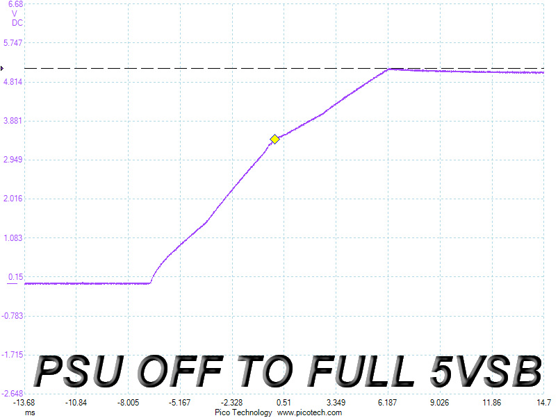
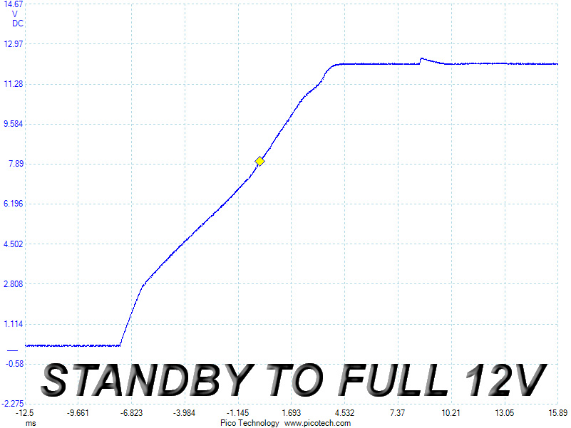
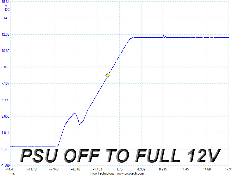
We didn't measure any voltage overshoots during the "turn-on" transient tests, but the last slope registered a small dive at around 4 V, and we noticed a strange small spike at +12V in both cases, after the rail voltage had stabilized. This spike is present on all KM3-based units we have tested so far, but it is too small to be of any concerns.
Jan 30th, 2025 00:42 EST
change timezone
Latest GPU Drivers
New Forum Posts
- Corsair Frame 4000D (3)
- What are you playing? (22697)
- HP Rx 460 Freezing, not booting all of a sudden after normal use. (8)
- HP Omen 30L is not working! (1)
- Your PC ATM (35214)
- Is disabling a select VRAM channel still a thing? (6)
- Possible to use NVCleanstall but also use Nvidia App? (15)
- Thermal paste instead of thermal putty/pads (3)
- ASUS TUF A15 FA507NVR (2024) Ryzen 7 7435HS + RTX 4060 8GB (18)
- RANT- front panel connectors are a crime against pc builders/users (57)
Popular Reviews
- NVIDIA GeForce RTX 5080 Founders Edition Review
- NVIDIA DLSS 4 Transformer Review - Better Image Quality for Everyone
- ASUS GeForce RTX 5090 Astral OC Review - Astronomical Premium
- NVIDIA GeForce RTX 5090 Founders Edition Review - The New Flagship
- MSI GeForce RTX 5090 Suprim SOC Review
- Galax GeForce RTX 5080 1-Click OC Review
- MSI GeForce RTX 5090 Suprim Liquid SOC Review
- KLEVV URBANE V DDR5-7600 32 GB CL36 Review
- Palit GeForce RTX 5090 GameRock Review
- NVIDIA GeForce RTX 5090 PCI-Express Scaling
Controversial News Posts
- NVIDIA 2025 International CES Keynote: Liveblog (470)
- AMD Debuts Radeon RX 9070 XT and RX 9070 Powered by RDNA 4, and FSR 4 (349)
- AMD is Taking Time with Radeon RX 9000 to Optimize Software and FSR 4 (244)
- AMD Radeon RX 9070 XT & RX 9070 Custom Models In Stock at European Stores (226)
- NVIDIA GeForce RTX 5090 Features 575 W TDP, RTX 5080 Carries 360 W TDP (217)
- AMD Denies Radeon RX 9070 XT $899 USD Starting Price Point Rumors (216)
- New Leak Reveals NVIDIA RTX 5080 Is Slower Than RTX 4090 (208)
- AMD's Radeon RX 9070 Launch Faces Pricing Hurdles (175)