 4
4
Cooltek U3 Review
Assembly & Finished Looks »A Closer Look - Inside
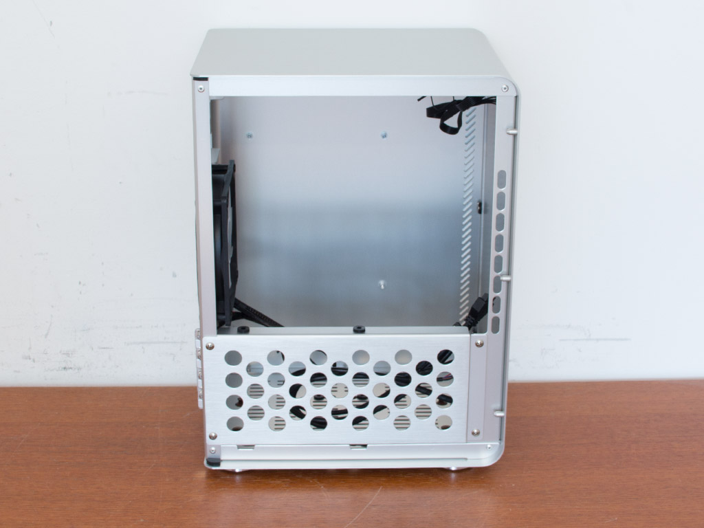
Take off the main side panel once the two thumbscrews have been removed to access the interior. There is obviously not a lot within the chassis as the bulk of space is for the motherboard. Removing the side panel will reveal another spot for a 3.5" hard drive. You must also remove this single cage for unobstructed access to the interior of the Cooltek U3.
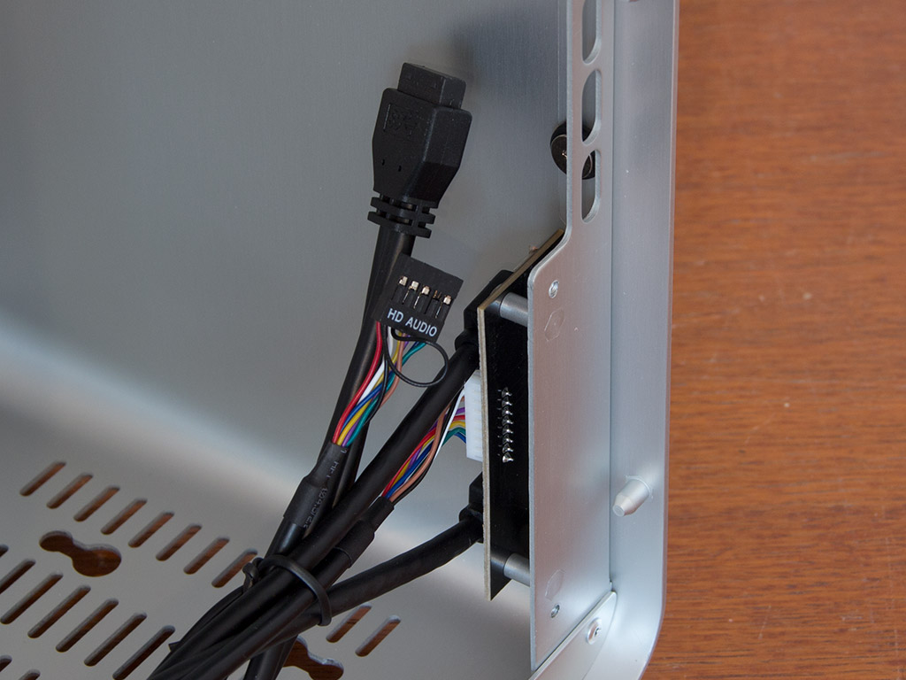
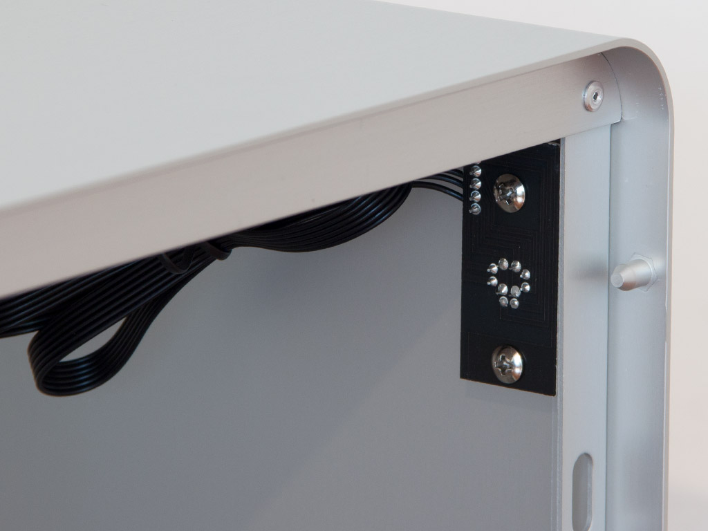
The front I/O PCB is held in place by two clearly visible screws. This also holds true for the power button PCB in the top of the front. Due to the compact nature of the chassis, these may get in the way of things when installing a mATX motherboard, which would mean removing the PCBs first—this may hold especially true for the power button PCB.
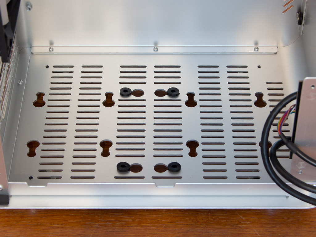
As we have noted before, the floor of the chassis is where you will be placing your hard drives. If you are installing a dual-GPU configuration, you may be force to use 2.5" drives in this area, though.
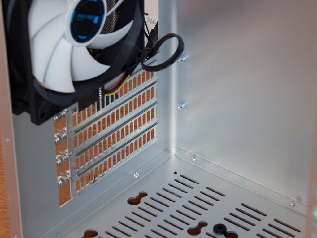
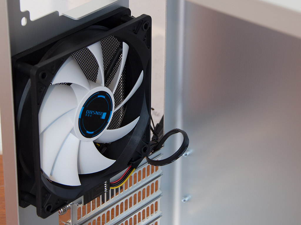
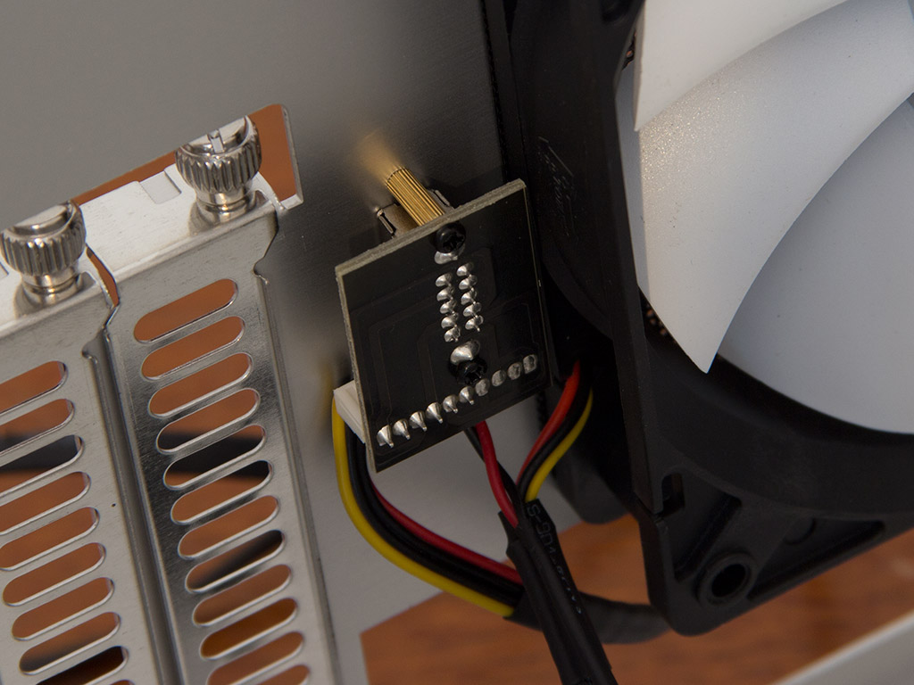

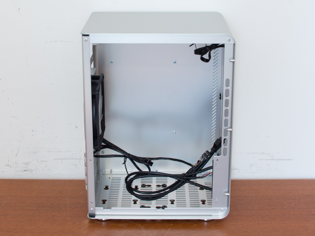
Turning our focus to the rear of the chassis, the motherboard-expansion slots are at the very bottom. Above that is the aforementioned fan and the little fan controller, which also utilizes a PCB. The PCB is a neat little addition because it allows you to swap the cooling unit out without losing the ability to control fan speed. The power supply bay in the very top comes with a little lip, which should aid in installing the unit within the Cooltek U3.
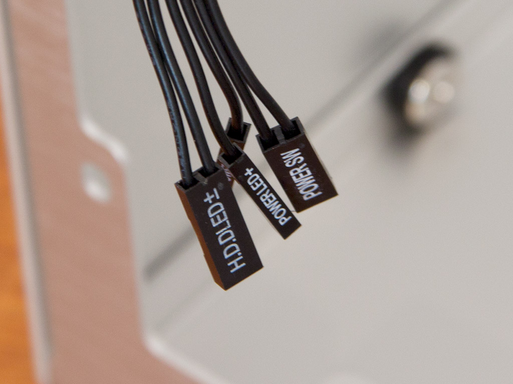
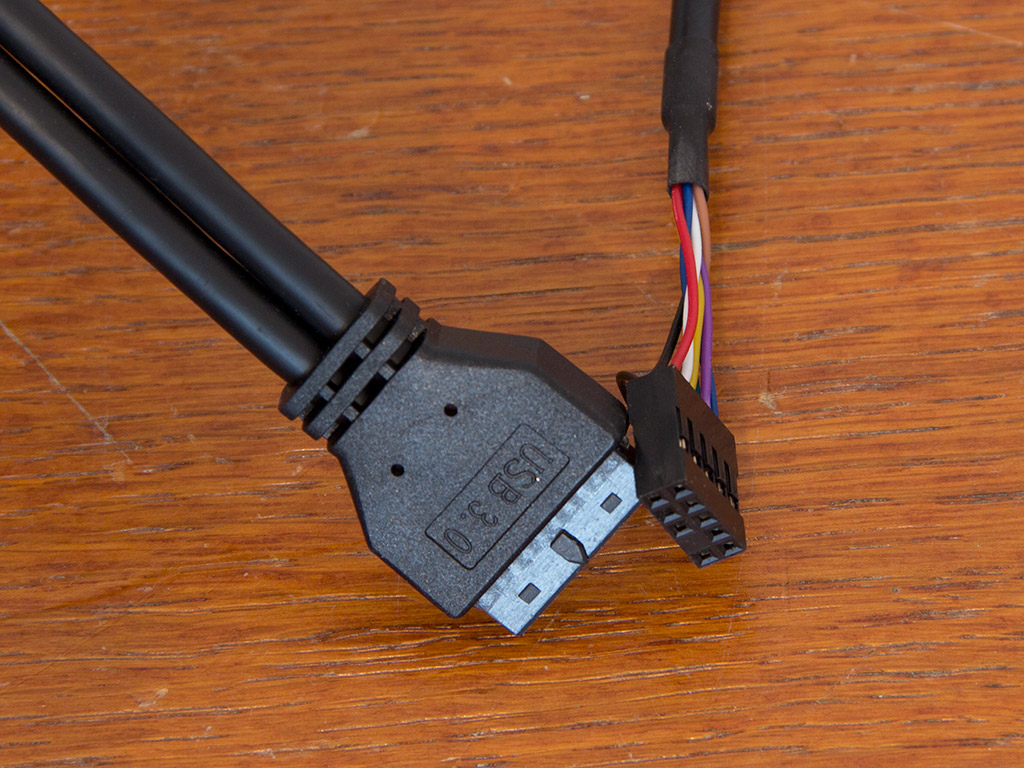
All the cables of the U3 are sleeved black and of the standard variety. As there is no reset button, you will not find those cables either. Both audio and USB connectors are of the standard variety, but a USB 2.0 plug would have been a nice addition as well.
Jan 31st, 2025 07:01 EST
change timezone
Latest GPU Drivers
New Forum Posts
- Paper launch 5080/5090 - is this a problem for Nvidia? (14)
- I dont like my new CPU Cooler (57)
- Asus PCE-AC55BT can I replace the WLAN card? (1)
- So who’s paying $100 for GTA 6 then? (109)
- NVIDIA RTX owners only - your opinion on DLSS Image quality (435)
- Will you buy a RTX 5090? (273)
- TPU's Nostalgic Hardware Club (19908)
- RTX 5080 - premature review - it sucks (134)
- What's your latest tech purchase? (23035)
- Please let me know if the UPS that I want to buy is good or not for my PC. (104)
Popular Reviews
- NVIDIA GeForce RTX 5080 Founders Edition Review
- NVIDIA DLSS 4 Transformer Review - Better Image Quality for Everyone
- Galax GeForce RTX 5080 1-Click OC Review
- ASUS GeForce RTX 5090 Astral OC Review - Astronomical Premium
- NVIDIA GeForce RTX 5090 Founders Edition Review - The New Flagship
- MSI GeForce RTX 5090 Suprim SOC Review
- MSI GeForce RTX 5080 Vanguard SOC Review
- ASUS GeForce RTX 5080 Astral OC Review
- MSI GeForce RTX 5090 Suprim Liquid SOC Review
- MSI GeForce RTX 5080 Suprim SOC Review
Controversial News Posts
- NVIDIA 2025 International CES Keynote: Liveblog (470)
- AMD Debuts Radeon RX 9070 XT and RX 9070 Powered by RDNA 4, and FSR 4 (349)
- AMD is Taking Time with Radeon RX 9000 to Optimize Software and FSR 4 (251)
- AMD Denies Radeon RX 9070 XT $899 USD Starting Price Point Rumors (234)
- AMD Radeon RX 9070 XT & RX 9070 Custom Models In Stock at European Stores (226)
- NVIDIA GeForce RTX 5090 Features 575 W TDP, RTX 5080 Carries 360 W TDP (217)
- New Leak Reveals NVIDIA RTX 5080 Is Slower Than RTX 4090 (214)
- AMD's Radeon RX 9070 Launch Faces Pricing Hurdles (175)