 20
20
Corsair K68 Mechanical Gaming Keyboard Review
Driver »Disassembly
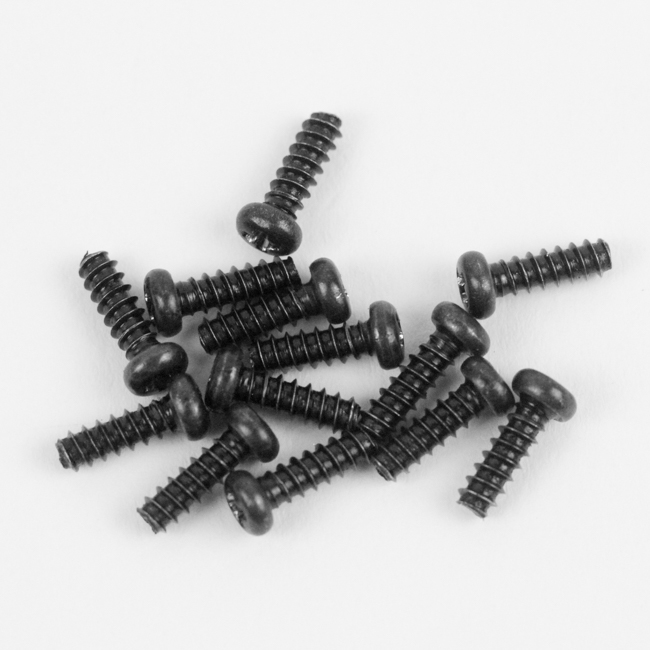

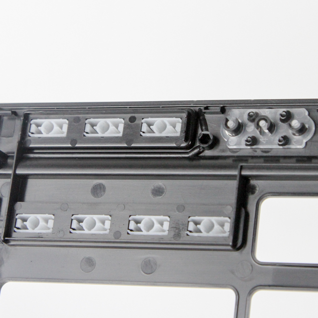
Disassembly of the Corsair K68 begins with the removal of thirteen Phillips head screws that hold the ABS plastic top panel and the rest of the keyboard together. Once done, as with nearly every plastic case keyboard, you have to use a thin, flat object to pry out the top panel locked in place via multiple plastic tabs around the edges. With that done, we get to see the membrane keycaps on the top panel piece that help actuate the various media keys.
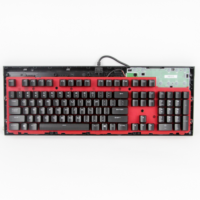
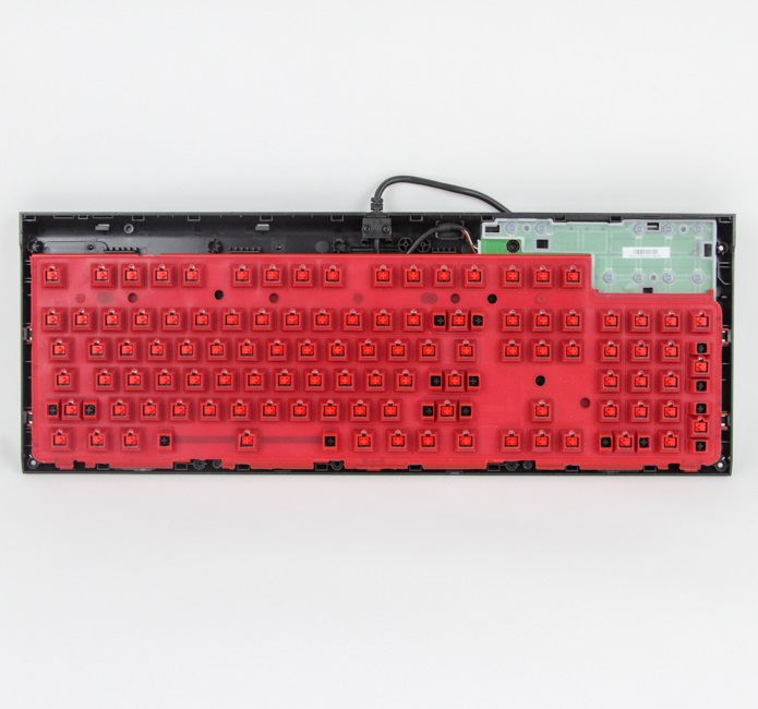

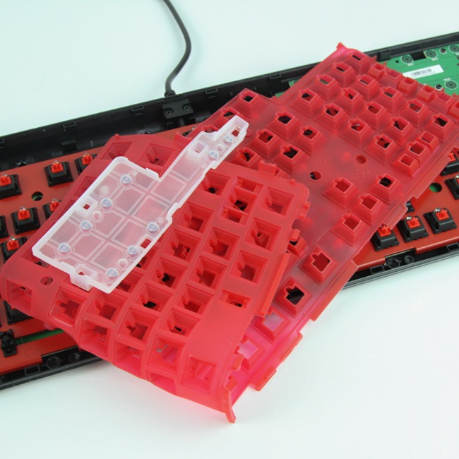
With the top panel removed, we have to now remove every single keycap in order to take a better look at the rubber molds and to access the second set of screws for the bottom panel piece. There are in fact two molds here, a large red-colored one for the main keyboard and a second smaller, translucent one for the media keys. Both have a raised edge on all sides to collect any spilled fluids or dust, and the keycaps help guide anything spilled away from the switch housing and LEDs. Please note that the IP32 rating does not mean this is waterproof, as there is no rubber O-ring seal keeping the PCB and switches completely isolated here, so treat it as you would any other keyboard and just consider there to be a better chance of survival in case of any spillage.

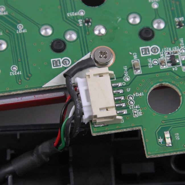
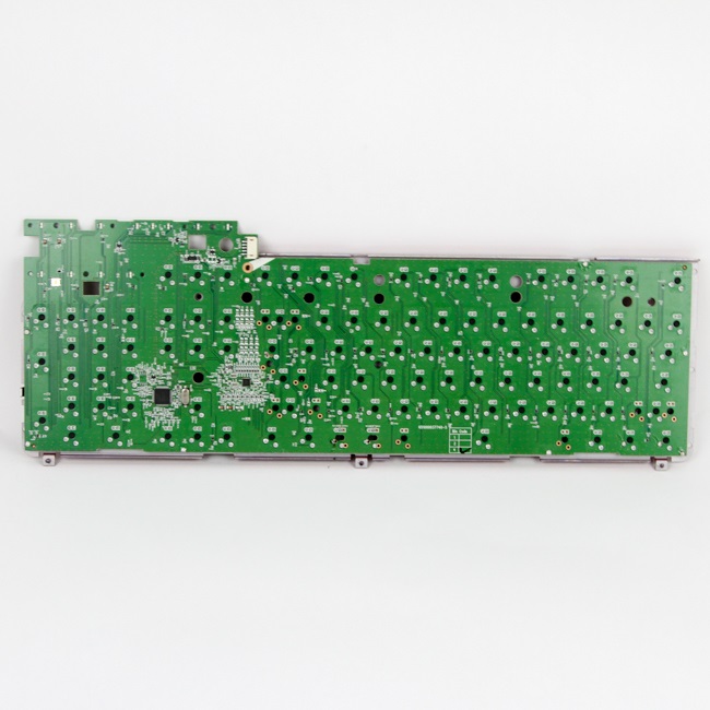
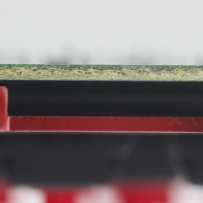
We now see more screws holding the PCB in place on the bottom panel piece, and removing these allows us to flip it over to where we see the internal USB connector and cable that need to be separated and the grounding screw that needs to be removed. Once done, we get a proper look at the PCB, green in color here, with a lot of components that are soldered in very well - likely an automated process to handle the volumes Corsair deals with too. A steel plate helps provide structural integrity to the unit.
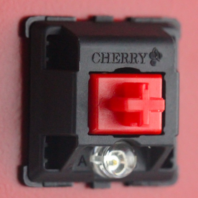
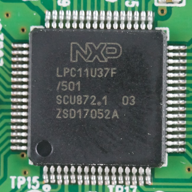
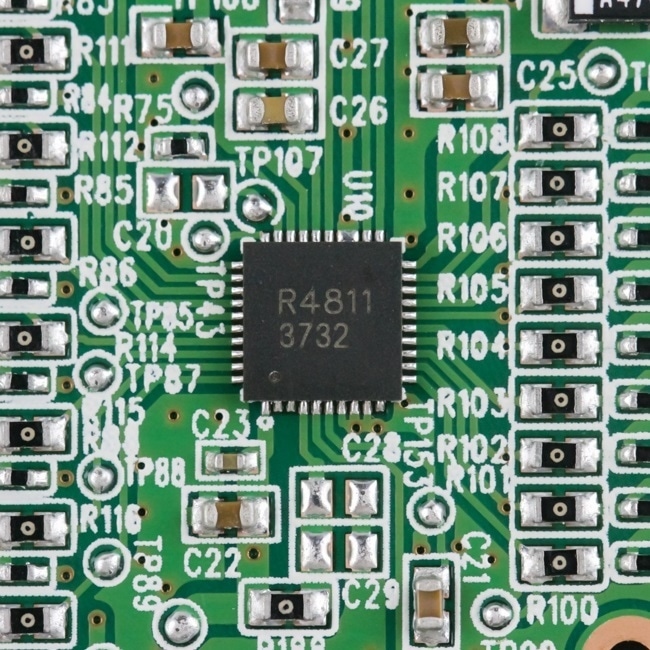
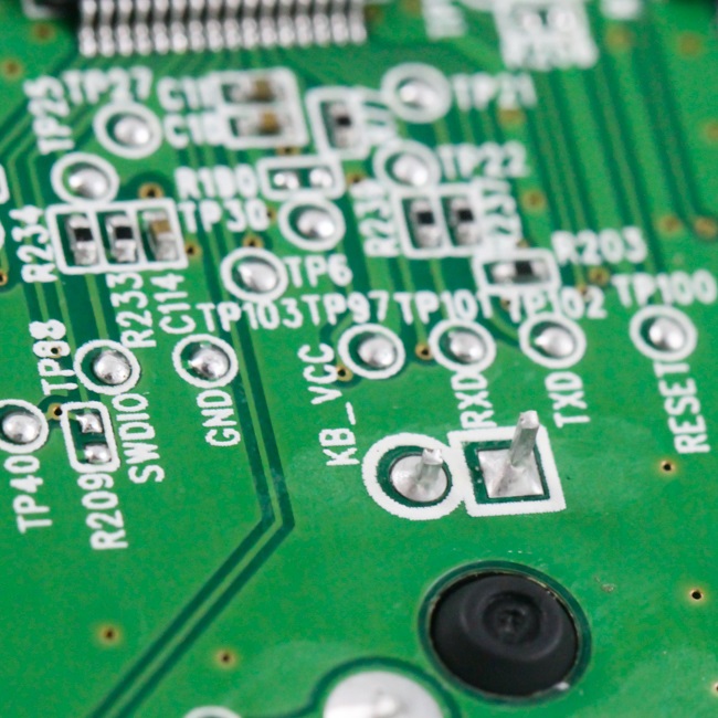
We see here the Cherry MX Red switches in more detail, now that the rubber mold is removed. Powering the Corsair K68 is an NXP LPC11U37x series 32-bit ARM Cortex-M0 USB microcontroller with up to 128 KB on-board flash memory, 12 KB SRAM, and 4 KB EEPROM. No need for dedicated RGB LED drivers here, so the rest of the keyboard is just switches, LEDs, and capacitors all soldered onto a multi-layer PCB.
Before we take a look at the driver, be advised that disassembly will void the warranty and that TechPowerUp is not liable for any damages incurred if you decide to go ahead and do so anyway.
Mar 10th, 2025 18:57 EDT
change timezone
Latest GPU Drivers
New Forum Posts
- Biostar RX 6700 XT OC BIOS (6)
- Nvidia's GPU market share hits 90% in Q4 2024 (gets closer to full monopoly) (774)
- What's your latest tech purchase? (23278)
- Wherein lies the difference (2)
- USB hard disk box capacity limits (14)
- AMD RX 7000 series GPU Owners' Club (1306)
- RX 9000 series GPU Owners Club (41)
- Gaming PC instabiliity (22)
- Msi 5090 DOA? (30)
- RX 9070 availability (170)
Popular Reviews
- Sapphire Radeon RX 9070 XT Nitro+ Review - Beating NVIDIA
- XFX Radeon RX 9070 XT Mercury OC Magnetic Air Review
- ASUS Radeon RX 9070 TUF OC Review
- MSI MAG B850 Tomahawk Max Wi-Fi Review
- NVIDIA GeForce RTX 5080 Founders Edition Review
- NVIDIA GeForce RTX 5070 Founders Edition Review
- Corsair Vengeance RGB CUDIMM DDR5-8800 48 GB CL42 Review
- AMD Ryzen 7 9800X3D Review - The Best Gaming Processor
- ASUS GeForce RTX 5070 Ti TUF OC Review
- MSI GeForce RTX 5070 Ti Gaming Trio OC+ Review
Controversial News Posts
- NVIDIA GeForce RTX 50 Cards Spotted with Missing ROPs, NVIDIA Confirms the Issue, Multiple Vendors Affected (513)
- AMD Plans Aggressive Price Competition with Radeon RX 9000 Series (277)
- AMD Radeon RX 9070 and 9070 XT Listed On Amazon - One Buyer Snags a Unit (261)
- AMD RDNA 4 and Radeon RX 9070 Series Unveiled: $549 & $599 (260)
- AMD Mentions Sub-$700 Pricing for Radeon RX 9070 GPU Series, Looks Like NV Minus $50 Again (248)
- NVIDIA Investigates GeForce RTX 50 Series "Blackwell" Black Screen and BSOD Issues (244)
- AMD Radeon RX 9070 and 9070 XT Official Performance Metrics Leaked, +42% 4K Performance Over Radeon RX 7900 GRE (195)
- AMD Radeon RX 9070-series Pricing Leaks Courtesy of MicroCenter (158)