 9
9
Gigabyte GA-A75-UD4H Socket FM1 Review
BIOS Walkthrough »The Board - A Closer Look

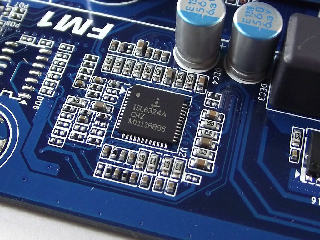

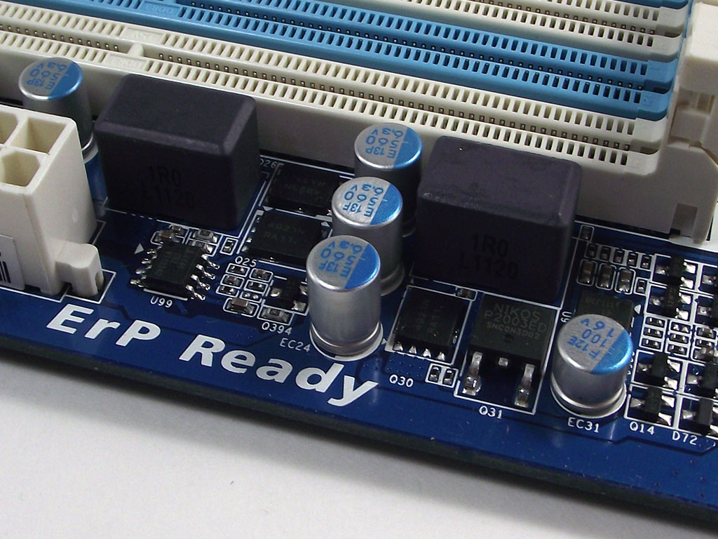
Starting with the BIOS, Gigabyte has equipped the A75-UD4H with a dual-BIOS solution, making for easy recovery when overclocking, and let us tell you, with this board, it really works. Employing an Intersil ISL6324a VRM controller, the A75-UD4H features an 8+2 VRM configuration with a two-part high/low MOSFET configuration, although the dual NB/GPU phases do feature dedicated input drivers as well. We find a single-phase DIMM VRM next to the memory slots, which doesn't seem like much, but did prove more than adequate during our testing phase.
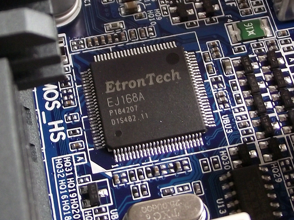
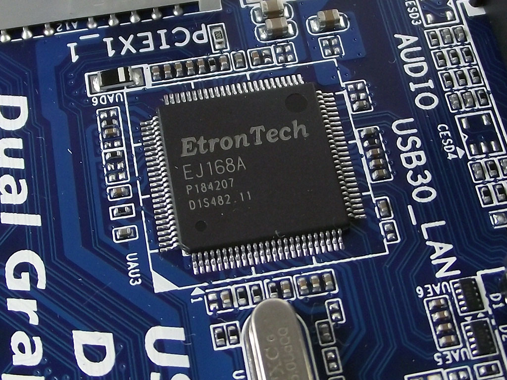
We find two separate Etron J168A USB 3.0 controllers onboard, each one dedicated to the near-by rear I/O tower with USB 3.0 slots. It's thanks to the use of these controllers that the Gigabyte A75-UD4H has a total of eight USB 3.0 ports, although this design decision can lead to installation issues in certain scenarios, as there are only two USB 2.0 ports on the rear I/O.
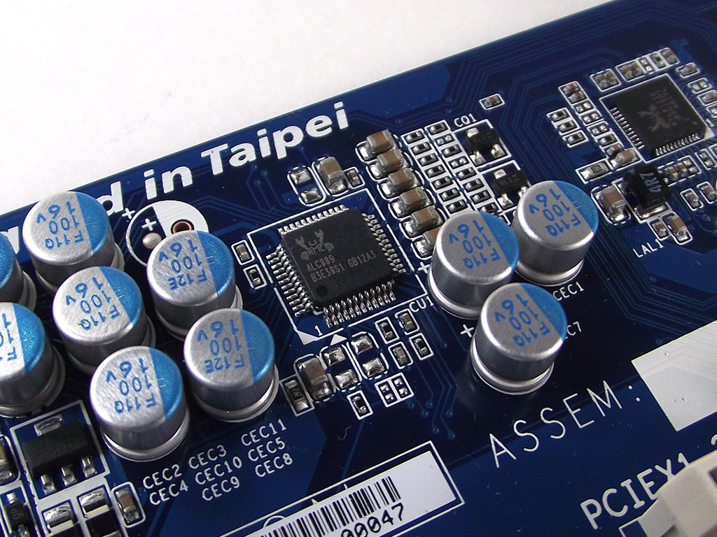
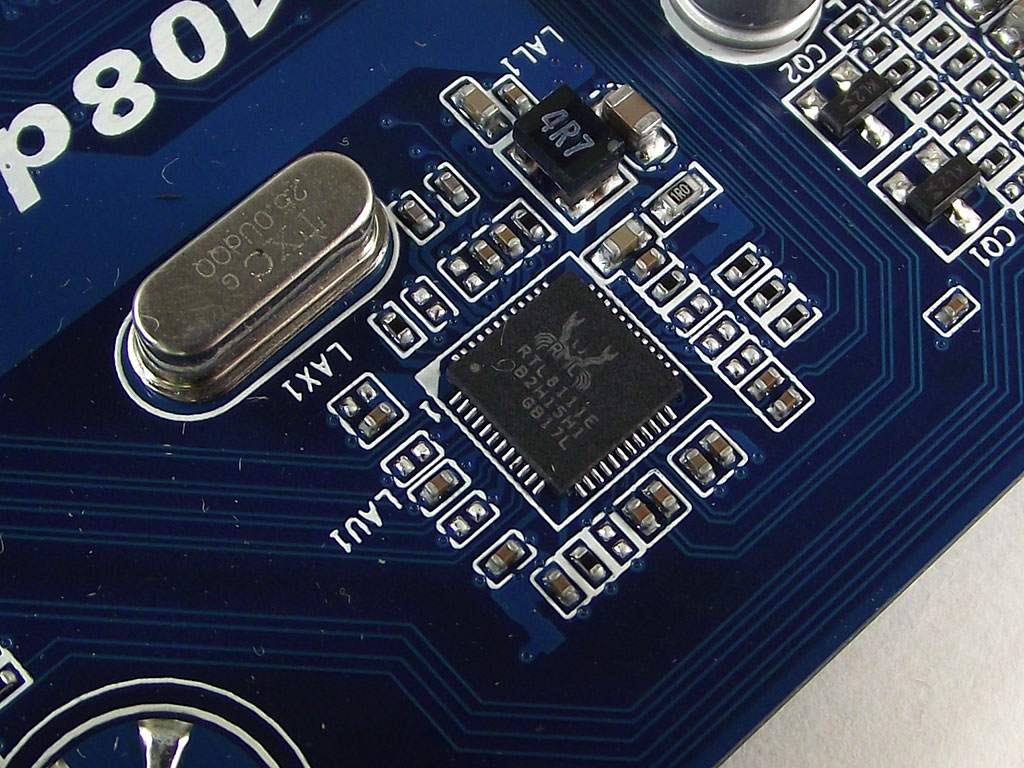
Realtek provides both audio and LAN controllers for the A75-UD4H, with the high-end, but common, ACL889 controller found for audio, while LAN support comes via the also common RTL8111E controller we have seen on many products throughout the industry.
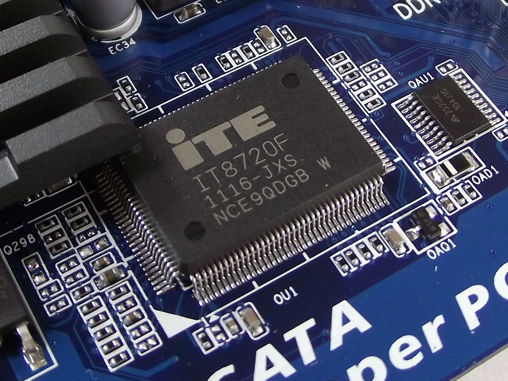
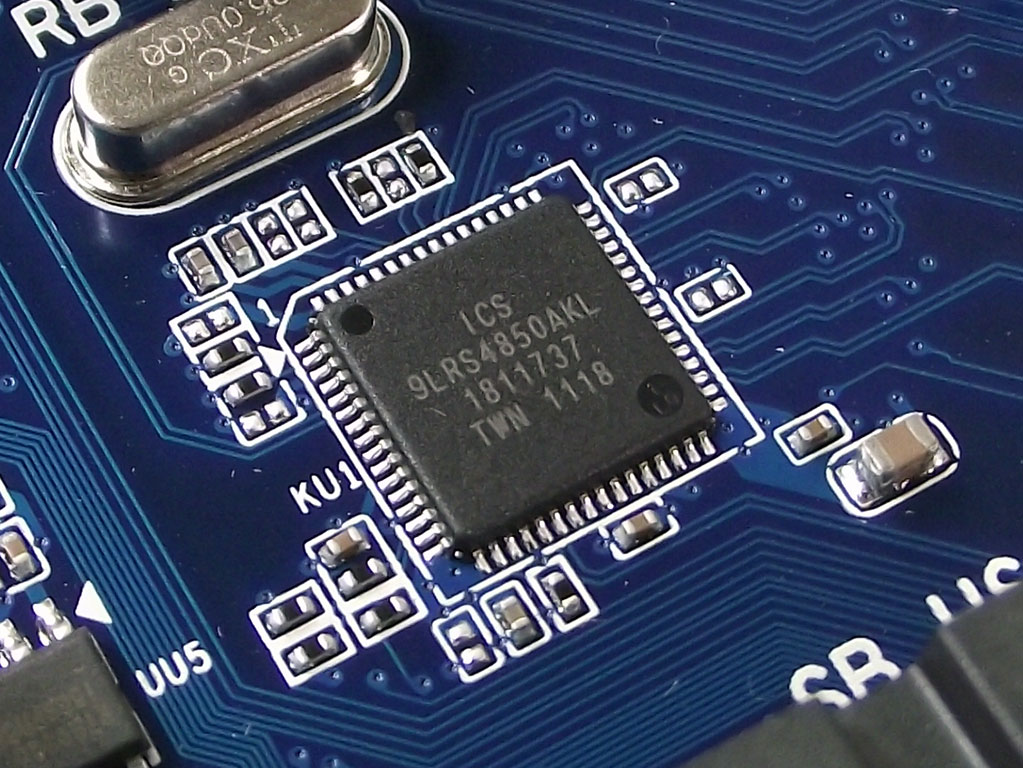
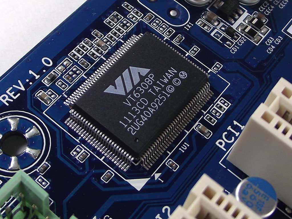
We find an ITE IT8720F for voltage monitoring and fan control, while the provided ICS 9LRS4850AKL PLL controller conforms to the FM1 AMD specifications, yet offering a bit more flexibility than some other options on the market today, can have a significant impact on overclocking with the A75-UD4H, too. FireWire support is provided by a VIA VT6803P controller, which not only powers the port on the rear I/O, but also offers an internal header too.
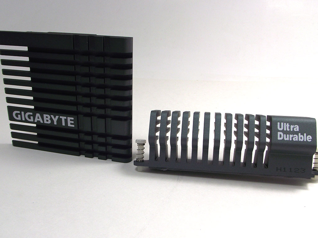
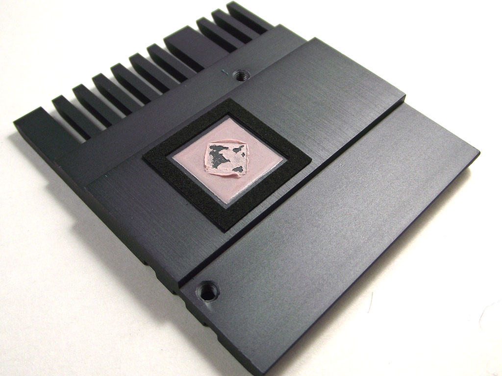
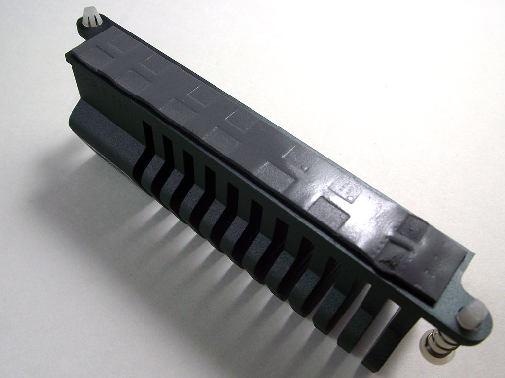
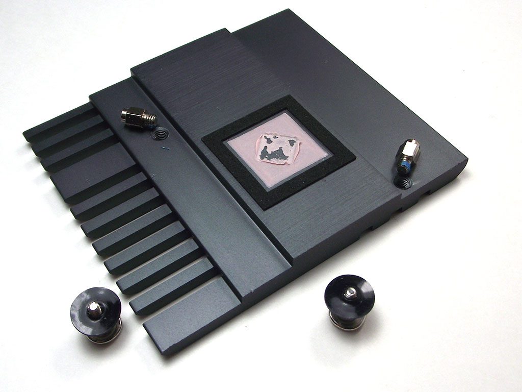
The matching cooling solutions provided with the A75-UD4H blend well with the color theme the board has, while providing more than ample cooling. The chipset cooler is very large, with many protruding fins, but maintains a low profile so as to not interfere with expansion cards. Gigabyte has chosen to use a standard thermal interface material, one that very closely resembles chewing gum, even with it's pink color, yet proves to provide excellent thermal transfer. The MOSFET cooler is equipped well too, with the thermal pad making full contact with the MOSFETs it sits over, as you can see by the impressions left in the pad.
We want to take a minute here and point out that although the chipset cooler employs screws that are easily removed, the cooler's design is such that its removal may not be so easy, as when we attempted to remove it for pictures, we found that the cooler's stand-offs backed out of the cooler rather than the screws coming out of the stand-offs, which could lead to board damage if care is not taken. Given that the cooler is so large, and thermal interfaces do provide more than sufficient contact, we suggest that users do not attempt to remove these coolers, and if there are any issues with them, to return the board to Gigabyte for repair, although we are confident that such will never need happen, thanks to an excellent design.
Apr 17th, 2025 07:51 EDT
change timezone
Latest GPU Drivers
New Forum Posts
- Can,t download Windows 11 or 10. (8)
- RX 9000 series GPU Owners Club (352)
- help needed (4)
- Is it worth buying a pi5 with a broken hdmi connector (8)
- SK hynix A-Die (Overclocking thread) only for RYZEN AM5 users (47)
- The TPU UK Clubhouse (26136)
- Windows 11 General Discussion (5993)
- Intel Iris XE Graphics Driver Issue. (7)
- my new mini pc (2)
- Memory Compression On or Off? (59)
Popular Reviews
- G.SKILL Trident Z5 NEO RGB DDR5-6000 32 GB CL26 Review - AMD EXPO
- ASUS GeForce RTX 5060 Ti TUF OC 16 GB Review
- NVIDIA GeForce RTX 5060 Ti PCI-Express x8 Scaling
- ASUS GeForce RTX 5080 TUF OC Review
- DAREU A950 Wing Review
- Palit GeForce RTX 5060 Ti Infinity 3 16 GB Review
- ASUS GeForce RTX 5060 Ti Prime OC 16 GB Review
- Zotac GeForce RTX 5060 Ti AMP 16 GB Review
- MSI GeForce RTX 5060 Ti Gaming OC 16 GB Review
- The Last Of Us Part 2 Performance Benchmark Review - 30 GPUs Compared
Controversial News Posts
- NVIDIA GeForce RTX 5060 Ti 16 GB SKU Likely Launching at $499, According to Supply Chain Leak (182)
- NVIDIA Sends MSRP Numbers to Partners: GeForce RTX 5060 Ti 8 GB at $379, RTX 5060 Ti 16 GB at $429 (127)
- Nintendo Confirms That Switch 2 Joy-Cons Will Not Utilize Hall Effect Stick Technology (105)
- Over 200,000 Sold Radeon RX 9070 and RX 9070 XT GPUs? AMD Says No Number was Given (100)
- Nintendo Switch 2 Launches June 5 at $449.99 with New Hardware and Games (99)
- NVIDIA Launches GeForce RTX 5060 Series, Beginning with RTX 5060 Ti This Week (92)
- Sony Increases the PS5 Pricing in EMEA and ANZ by Around 25 Percent (85)
- NVIDIA PhysX and Flow Made Fully Open-Source (77)