 4
4
High Power Astro GD 750 W Review
Ripple Measurements »Advanced Transient Response Tests
In these tests, we monitor the response of the PSU in two different scenarios. First, a transient load (10 A at +12V, 5 A at 5V, 5 A at 3.3V, and 0.5 A at 5VSB) is applied to the PSU for 200 ms while the latter is working at a 20% load state. In the second scenario, the PSU, while working at 50% load, is hit by the same transient load. In both tests, we measure the voltage drops that the transient load causes using our oscilloscope. The voltages should remain within the regulation limits defined by the ATX specification. We must stress here that the above tests are crucial since they simulate transient loads that a PSU is very likely to handle (e.g., booting a RAID array, an instant 100% load of CPU/VGAs, etc.). We call these tests "Advanced Transient Response Tests", and they are designed to be very tough to master, especially for PSUs with capacities lower than 500 W.| Advanced Transient Response 20% | ||||
|---|---|---|---|---|
| Voltage | Before | After | Change | Pass/Fail |
| 12 V | 12.030V | 11.846V | 1.53% | Pass |
| 5 V | 5.006V | 4.911V | 1.90% | Pass |
| 3.3 V | 3.297V | 3.175V | 3.70% | Pass |
| 5VSB | 5.115V | 5.072V | 0.84% | Pass |
| Advanced Transient Response 50% | ||||
|---|---|---|---|---|
| Voltage | Before | After | Change | Pass/Fail |
| 12 V | 12.010V | 11.879V | 1.09% | Pass |
| 5 V | 4.996V | 4.886V | 2.20% | Pass |
| 3.3 V | 3.293V | 3.151V | 4.31% | Pass |
| 5VSB | 5.086V | 5.044V | 0.83% | Pass |
Performance is satisfactory on all rails except the 3.3V one. We would still like to see lower deviations, especially on the +12V rail. Out of a unit of this category, we expect deviations of within 1% on the aforementioned rail and deviations below 3% on all other rails. In this case, the 3.3V rail registered a deviation of over 4% during the second test, so its voltage dropped dangerously close to the lower limit the ATX spec sets.
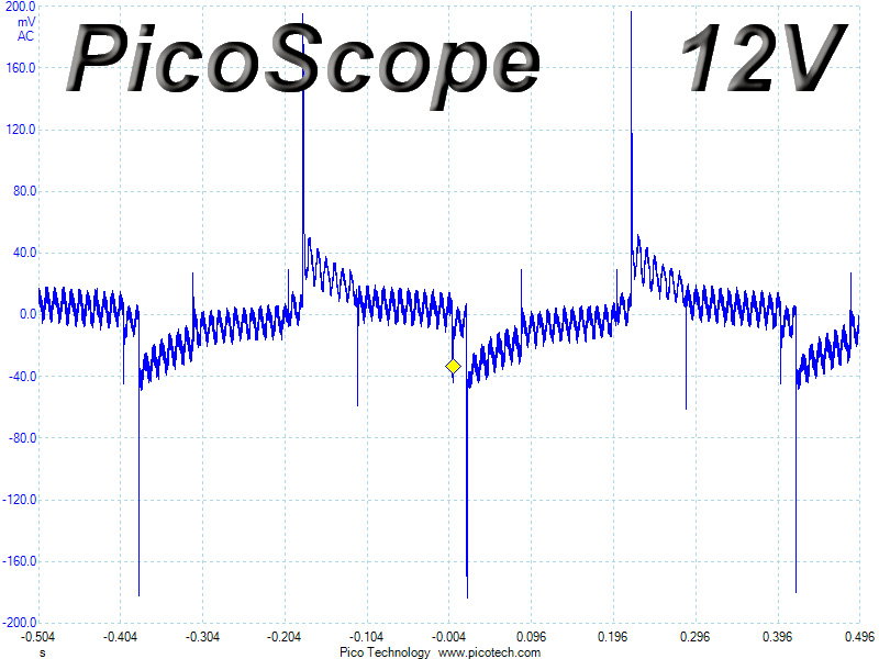
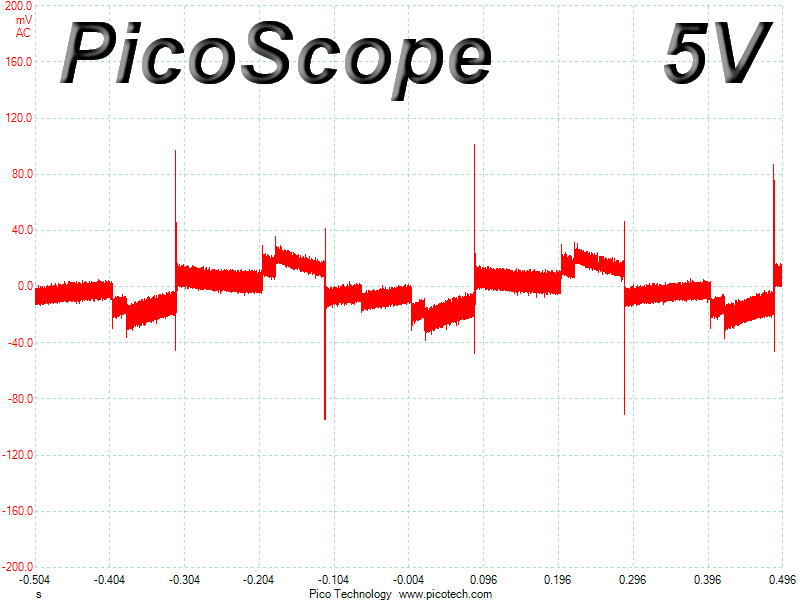
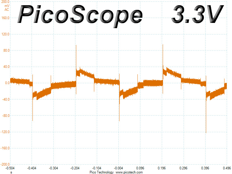
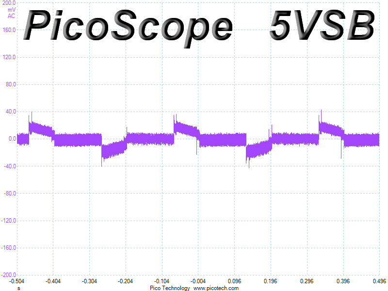
Below, you will find the oscilloscope screenshots we took during Advanced Transient Response Testing.
Transient Response at 20% Load
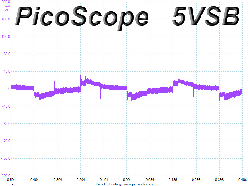
Transient Response at 50% Load
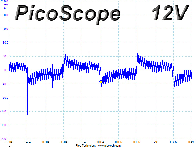
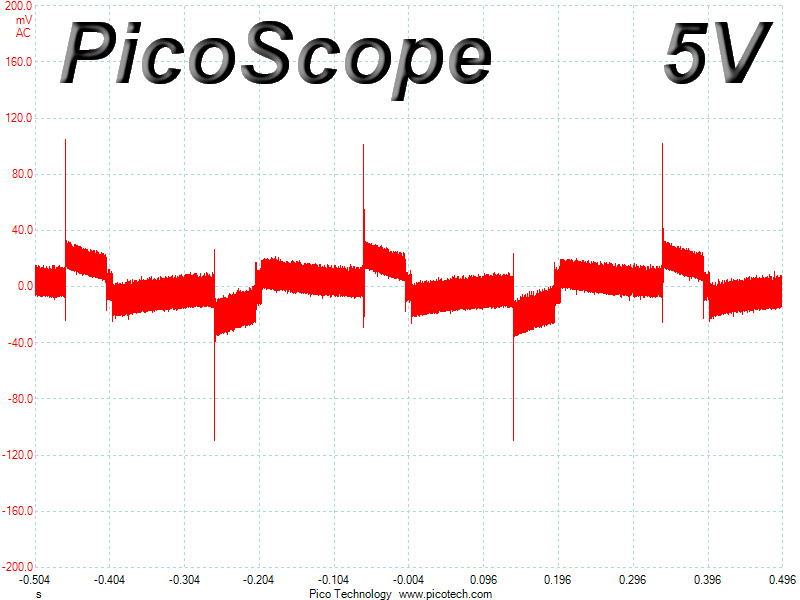
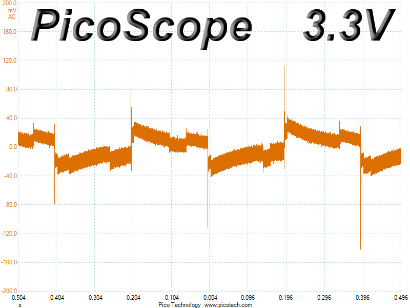
Turn-On Transient Tests
We measure the response of the PSU in simpler scenarios of transient loads—during the power-on phase of the PSU—in the next set of tests. In the first test, we turn the PSU off, dial the maximum current that the 5VSB can output, and then switch on the PSU. In the second test, we dial the maximum load that +12V can handle and start the PSU while the PSU is in standby mode. In the last test, while the PSU is completely switched off (we cut off power or switch off the PSU's on/off switch), we dial the maximum load that the +12V rail can handle before switching the PSU on from the loader and restoring power. The ATX specification states that recorded spikes on all rails should not exceed 10% of their nominal values (e.g., +10% for 12V is 13.2V and 5.5V for 5V).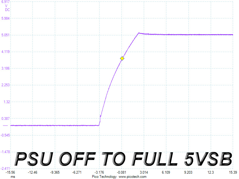
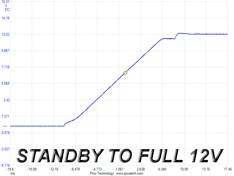
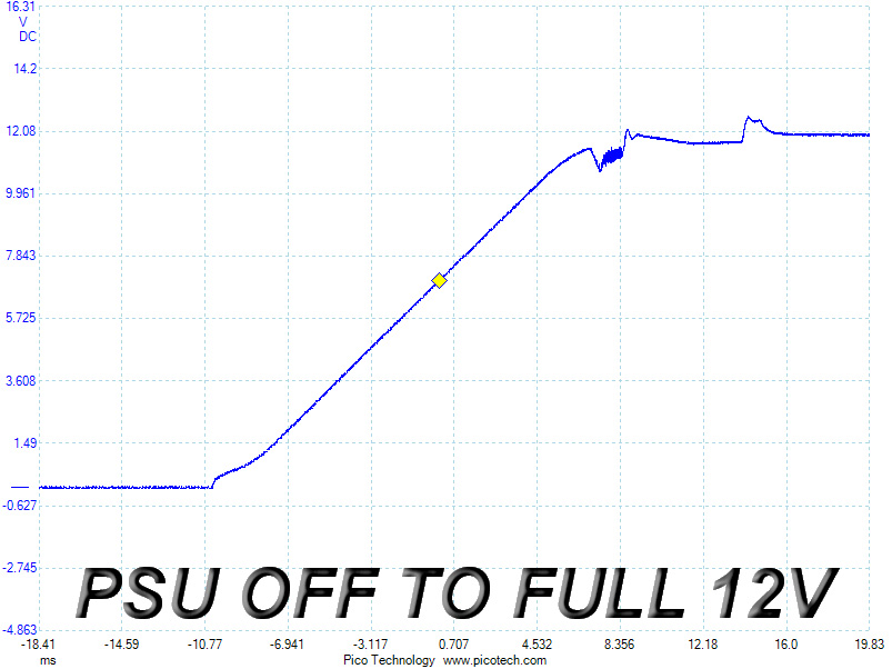
We noticed a small spike on the 5VSB rail. Two further voltage overshoots also took place during the other two tests, yet all slopes ramped up smoothly to their regular voltage levels, and all spikes were much lower than the maximum allowed values.
Mar 1st, 2025 10:18 EST
change timezone
Latest GPU Drivers
New Forum Posts
- How many continuous hours will it last my mini pc if connected to the LiitoKala battery pack that I've found for a cheap price ? (30)
- DTS DCH Driver for Realtek HDA [DTS:X APO4 + DTS Interactive] (2105)
- Recommended PhysX card for 5xxx series? [Is vRAM relevant?] (24)
- GPU-Z update with ROPs warning, e.g. red letters/box (0)
- Basic web browsing PC (35)
- It's happening again, melting 12v high pwr connectors (975)
- AAF Optimus Modded Driver For Windows 10 & Windows 11 - Only for Realtek HDAUDIO Chips (349)
- Update: AMD releases 9070XT comparison to 5070Ti (6)
- Ram downclocking after restart. (1)
- 14900ks vs 7950x3d paired with 7900xtx. (8)
Popular Reviews
- AMD Radeon RX 9070 Series Technical Deep Dive
- Montech HyperFlow Silent 360 Review
- Gigabyte X870 Aorus Elite WiFi 7 Review
- ASUS GeForce RTX 5070 Ti TUF OC Review
- ASUS ROG Harpe Ace Mini Review
- be quiet! Pure Base 501 DX Review
- Corsair Xeneon 34WQHD240-C Review - Pretty In White
- AMD Ryzen 7 9800X3D Review - The Best Gaming Processor
- MSI GeForce RTX 5070 Ti Vanguard SOC Review
- MSI GeForce RTX 5070 Ti Ventus 3X OC Review
Controversial News Posts
- NVIDIA GeForce RTX 50 Cards Spotted with Missing ROPs, NVIDIA Confirms the Issue, Multiple Vendors Affected (498)
- AMD Plans Aggressive Price Competition with Radeon RX 9000 Series (274)
- AMD Radeon RX 9070 and 9070 XT Listed On Amazon - One Buyer Snags a Unit (255)
- AMD Mentions Sub-$700 Pricing for Radeon RX 9070 GPU Series, Looks Like NV Minus $50 Again (248)
- NVIDIA Investigates GeForce RTX 50 Series "Blackwell" Black Screen and BSOD Issues (244)
- Edward Snowden Lashes Out at NVIDIA Over GeForce RTX 50 Pricing And Value (243)
- AMD RDNA 4 and Radeon RX 9070 Series Unveiled: $549 & $599 (204)
- AMD Radeon RX 9070 and 9070 XT Official Performance Metrics Leaked, +42% 4K Performance Over Radeon RX 7900 GRE (191)