 0
0
iKBC F87 RGB Keyboard Review
Driver & Performance »Disassembly
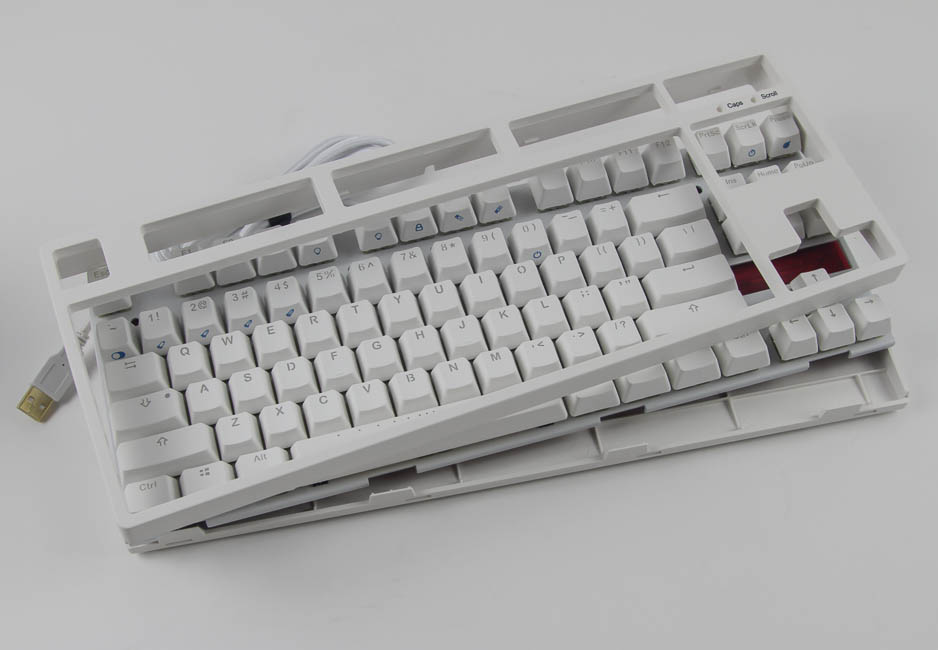
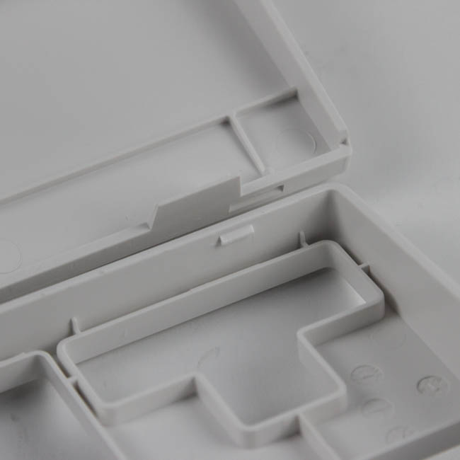

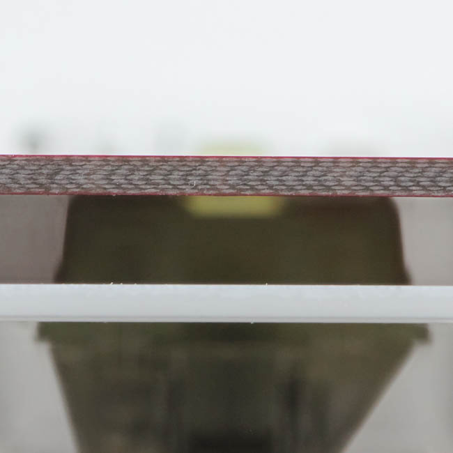
Disassembling the iKBC F87 is really simple since there are no screws keeping the top and bottom panel pieces together. There are instead multiple plastic tabs that hook into each other, and you need to take a thin, flat object to pry them apart. As per usual, be careful lest you scratch the plastic. Once done, remove the internal USB connector from the PCB to separate the middle piece from the bottom plastic panel piece.
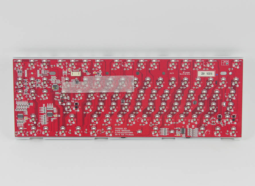
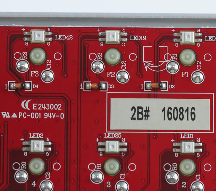
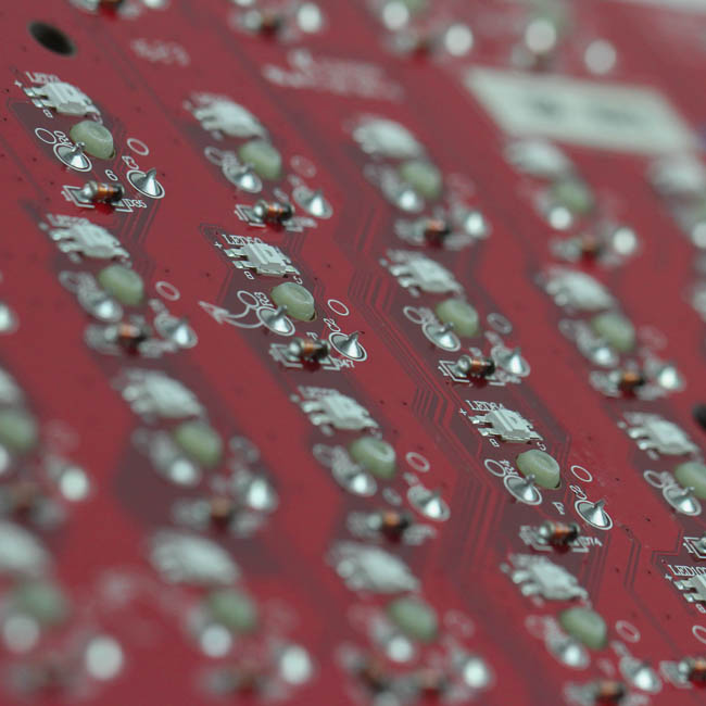
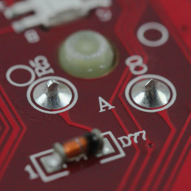
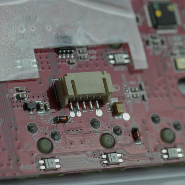
The middle piece has the switches soldered through the metal plate and into the red PCB, which was finalized on August 16, 2016 as per the label here. There is a piece of insulating rubber on the PCB by the USB connector, although I am not sure why given the absence of any metal screws here. Solder quality here is nothing to brag about and could be improved. There are unshapely peaks everywhere, including some that are close to each other.
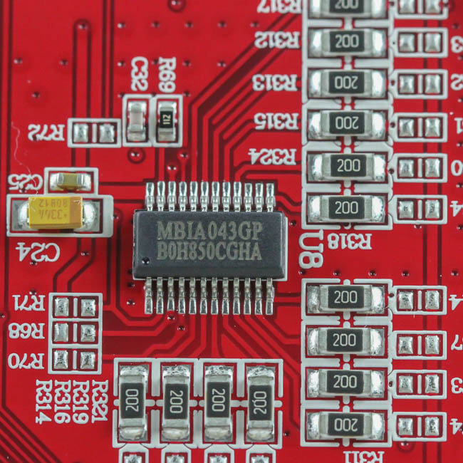
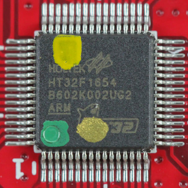
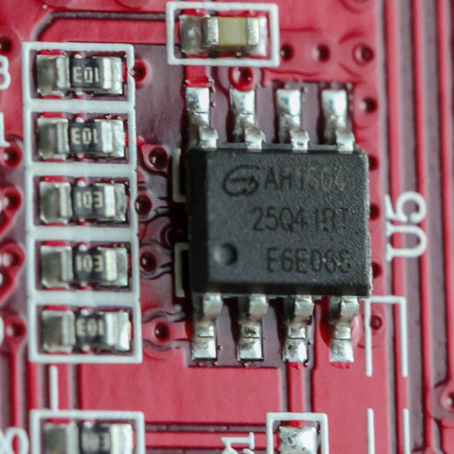
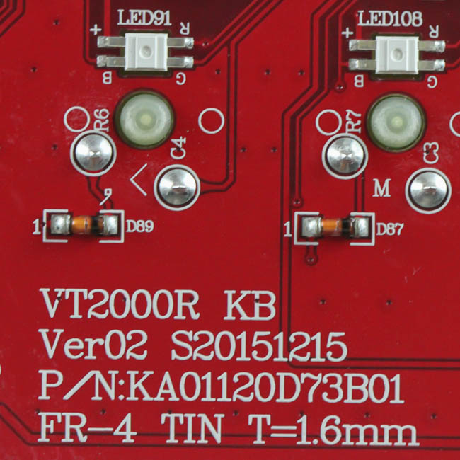
The component choices are well done, with the usual tantalum caps strewn in between as well. Powering the iKBC F87 RGB is a Macroblock MBIA043GP LED driver, the 32-bit ARM Cortex Holtek HT32F1654 MCU, and 4 Mb of flash memory from the 25Q41BT flash module. The LED driver has been used before with other RGB keyboards, including the Vortex CORE RGB engineering sample I received, without any issues, but everything is limited to hardware lighting control only. As per usual, the iKBC F87 RGB uses a multi-layered PCB.
Before we take a look at the driver, be advised that disassembly will void the warranty and that TechPowerUp is not liable for any damages incurred if you decided to go ahead and do so anyway.
Mar 10th, 2025 00:33 EDT
change timezone
Latest GPU Drivers
New Forum Posts
- Gaming PC instabiliity (5)
- As we live the age of game remakes, which game you would like to see to have a remake? (353)
- Unigine Superposition GPU Benchmark (1080P Extreme) (405)
- What are you playing? (23116)
- What's your latest tech purchase? (23264)
- *Severe micro stutters* cyberpunk 2077 Please help (54)
- RX 9070 availability (96)
- Nvidia's GPU market share hits 90% in Q4 2024 (gets closer to full monopoly) (736)
- Zen6 is almost here ? (42)
- Iccmax can't be altered on Throttlestop (2)
Popular Reviews
- Sapphire Radeon RX 9070 XT Nitro+ Review - Beating NVIDIA
- XFX Radeon RX 9070 XT Mercury OC Magnetic Air Review
- ASUS Radeon RX 9070 TUF OC Review
- MSI MAG B850 Tomahawk Max Wi-Fi Review
- NVIDIA GeForce RTX 5080 Founders Edition Review
- NVIDIA GeForce RTX 5070 Founders Edition Review
- Corsair Vengeance RGB CUDIMM DDR5-8800 48 GB CL42 Review
- AMD Ryzen 7 9800X3D Review - The Best Gaming Processor
- ASUS GeForce RTX 5070 Ti TUF OC Review
- MSI GeForce RTX 5070 Ti Gaming Trio OC+ Review
Controversial News Posts
- NVIDIA GeForce RTX 50 Cards Spotted with Missing ROPs, NVIDIA Confirms the Issue, Multiple Vendors Affected (513)
- AMD Plans Aggressive Price Competition with Radeon RX 9000 Series (277)
- AMD Radeon RX 9070 and 9070 XT Listed On Amazon - One Buyer Snags a Unit (261)
- AMD RDNA 4 and Radeon RX 9070 Series Unveiled: $549 & $599 (259)
- AMD Mentions Sub-$700 Pricing for Radeon RX 9070 GPU Series, Looks Like NV Minus $50 Again (248)
- NVIDIA Investigates GeForce RTX 50 Series "Blackwell" Black Screen and BSOD Issues (244)
- AMD Radeon RX 9070 and 9070 XT Official Performance Metrics Leaked, +42% 4K Performance Over Radeon RX 7900 GRE (195)
- AMD Radeon RX 9070-series Pricing Leaks Courtesy of MicroCenter (158)