 3
3
LEPA MaxPlatinum Series 1700 W Review
Load Regulation, Hold-up Time & Inrush Current »A Look Inside & Component Analysis
Before reading this page, we strongly suggest a look at this article, which will help you understand the internal components of a PSU much better. Our main tool for the disassembly of the PSU is a Thermaltronics TMT-9000S soldering and rework station. It is of extreme quality and is equipped with a matching de-soldering gun. With such equipment in hand, breaking apart every PSU is like a walk in the park!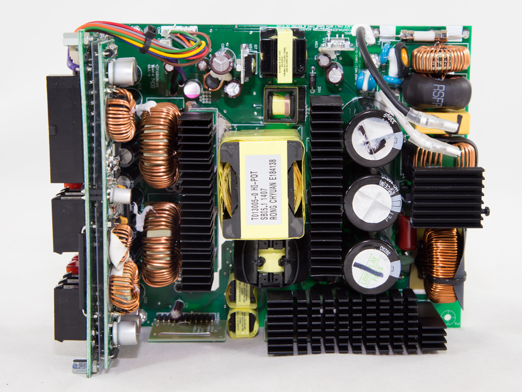
| LEPA P1700-MA-EU Parts Description | |
|---|---|
| Primary Side | |
| Transient Filter | Integrated Filter YO15T1 (2x Y caps, 1x X caps, 2x chokes), 4x Y caps, 1x X caps, 3x CM chokes, 1x MOV |
| Bridge Rectifier(s) | 1x GBU2006 (600V, 20A @ 87°C) |
| Inrush Current Protection | NTC Thermistor & Relay |
| APFC Mosfets | 2x Infineon SPW35N60C3 (650V, 21.9A @ 100°C, 0.1Ω ) |
| APFC Boost Diode | 1x |
| Hold-up Cap(s) | 3x Panasonic/Matsushita (400V, 330uF each or 990uF combined, 105°C, HC series, 2000h lifetime) |
| Main Switchers | 2x Toshiba TK18A60V (600V, 18A @ 100°C, 0.19Ω, TO-220-3) |
| APFC Controller | Infineon ICE3PCS01G |
| Switching Controller | Texas Instruments UCC28950 - UCC27324 |
| Topology | Primary side: Full Bridge Secondary side: Synchronous Rectification & DC-DC converters |
| Secondary Side | |
| +12V | 8x Infineon IPP015N04N G (40V, 120A @ 100°C, 1.5mΩ) |
| 5V & 3.3V | DC-DC Converters: 8x Sinopower APM2556N fets (30V, 48A @ 100°C, 6.9mΩ @ 125°C) PWM Controllers: 2x APW7073 |
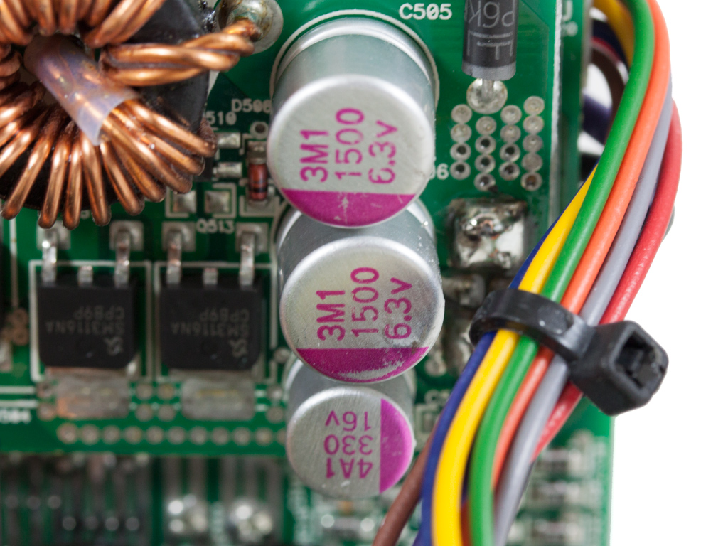
| Filtering Capacitors | Electrolytics: 10x Rubycon (16V, 1500μF, 105°C, ZLK series, 5000h lifetime) Chemi-Con (105°C, KY series) Polymers: Enesol (Korean) |
| Supervisor IC | PS238 |
| Fan Model | ADDA ADN512UB-A90 (135mm, 12 V, 0.44 A, double ball-bearings) |
| 5VSB Circuit | |
| Standby PWM Controller | TOPSwitch-JX TOP265 |
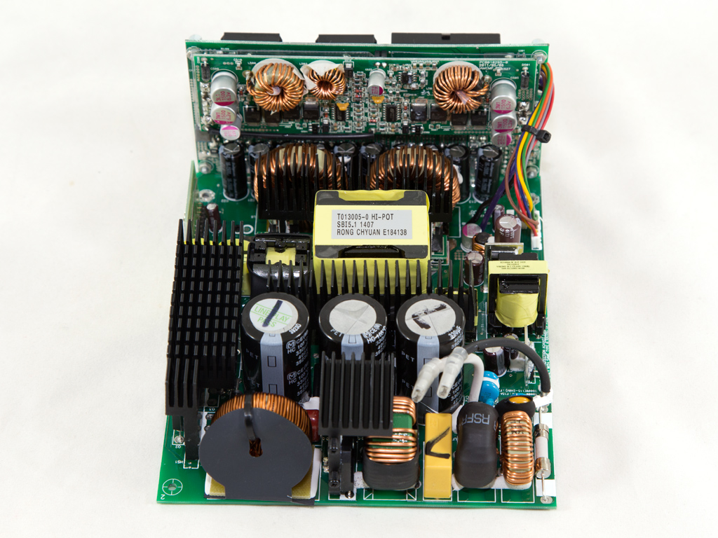
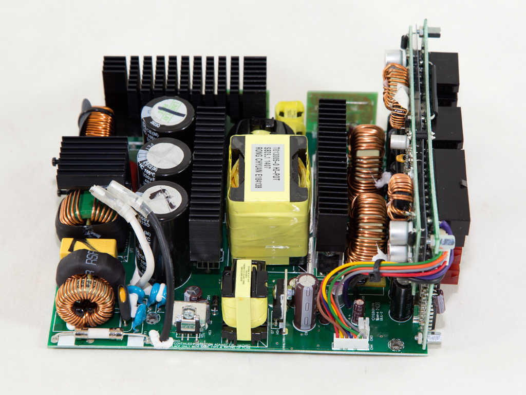
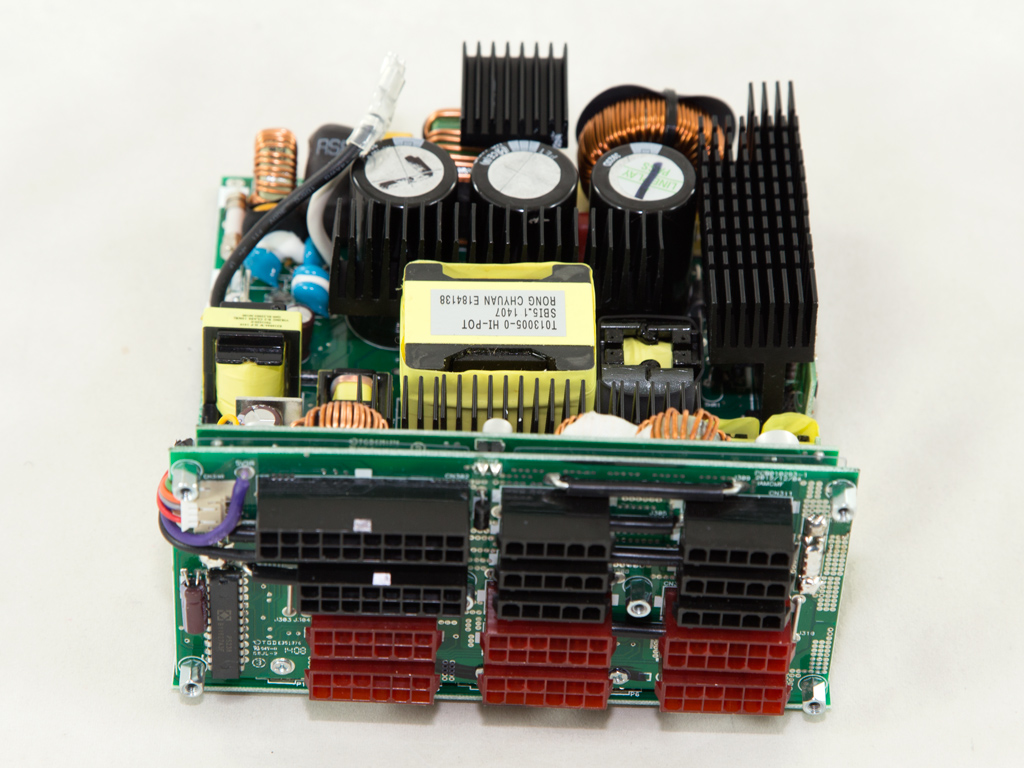
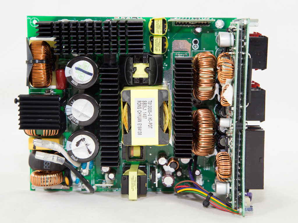
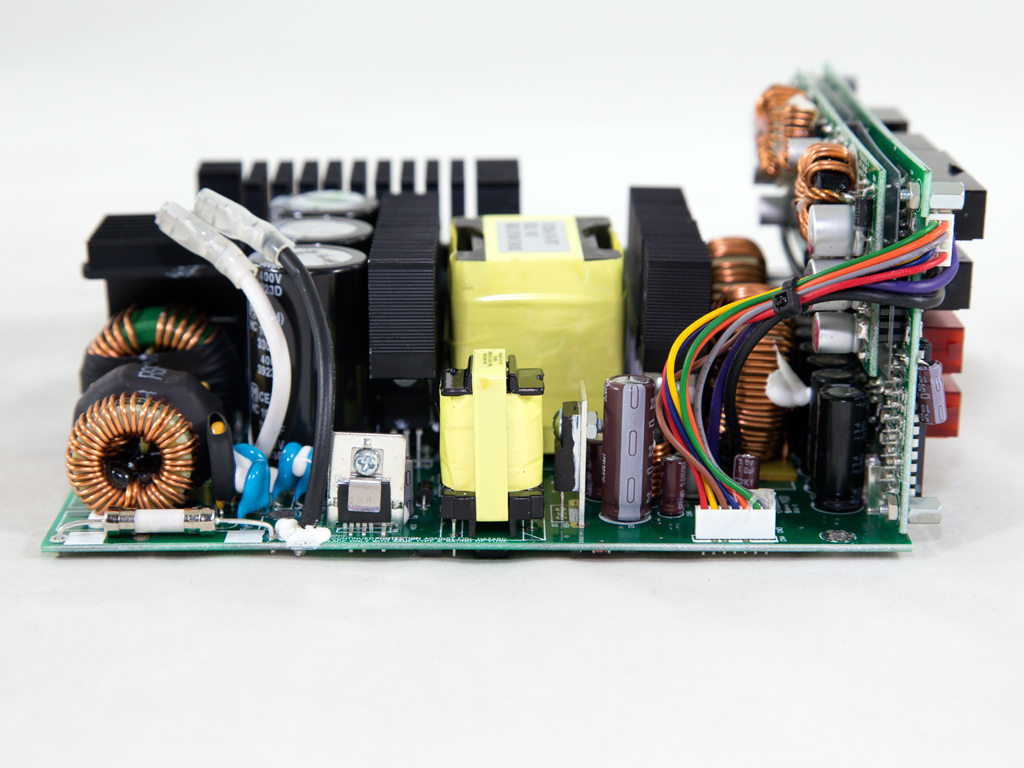
The platform is the same as in the LEPA G1600-MA PSU, the MaxRevo, and high capacity Platimax units. The design is very clean, and still preforms well by today's standards, although already in production for some years. The primary side consists of a ZVS phase-shifted full-bridge topology, while the secondary side uses synchronous rectification to generate the +12V rail, with a pair of VRMs (Voltage Regulation Modules) to handle the minor voltages.
The AC receptacle incorporates a complete line filter (YO15T1, provided by Yunpen). The EMI/transient filter continues on the main PCB with three CM chokes, one X and four Y caps, and an MOV.
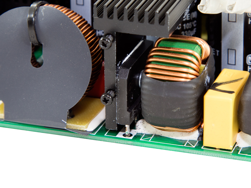
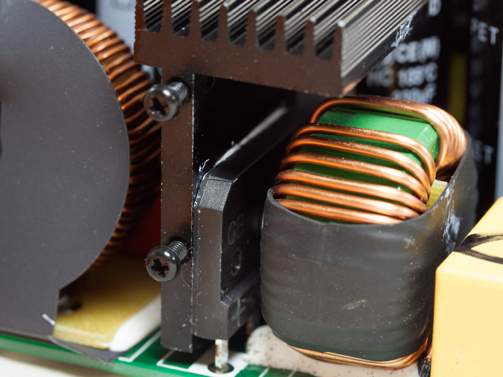
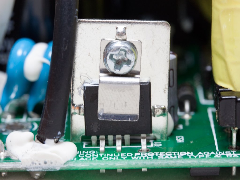
The single bridge rectifier is bolted to a dedicated heatsink, and its model number is GBU2006. It can handle up to 20 A of current, which is enough to cover this unit's requirements. The large PFC choke, or boost inductor, and the PFC input capacitor have been put behind the bridge.
The NTC thermistor that protects the unit from large inrush currents is well hidden by the APFC's heatsink. It is supported by an electromagnetic relay.
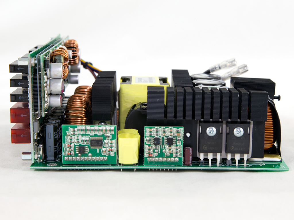
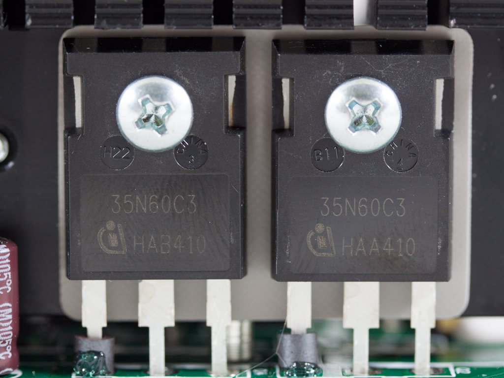
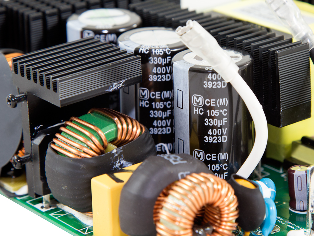
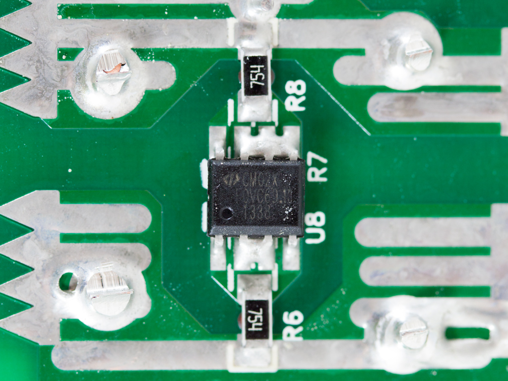
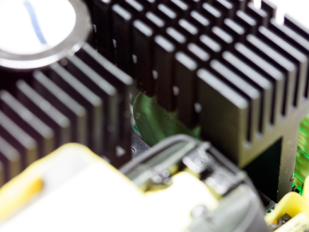
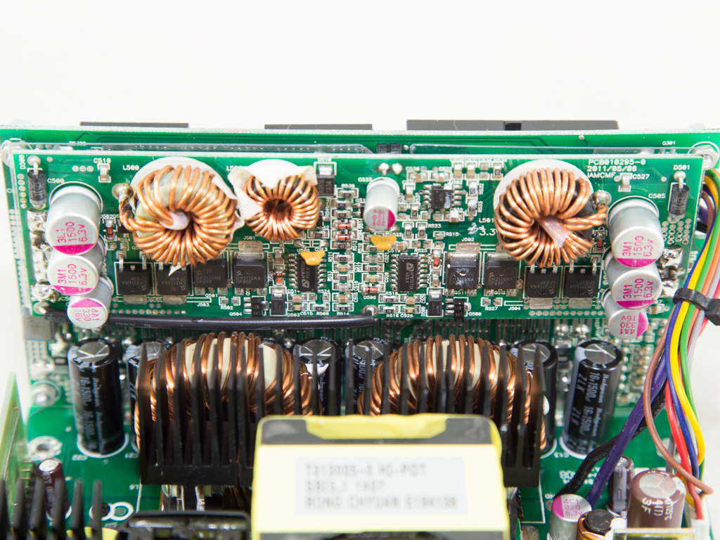
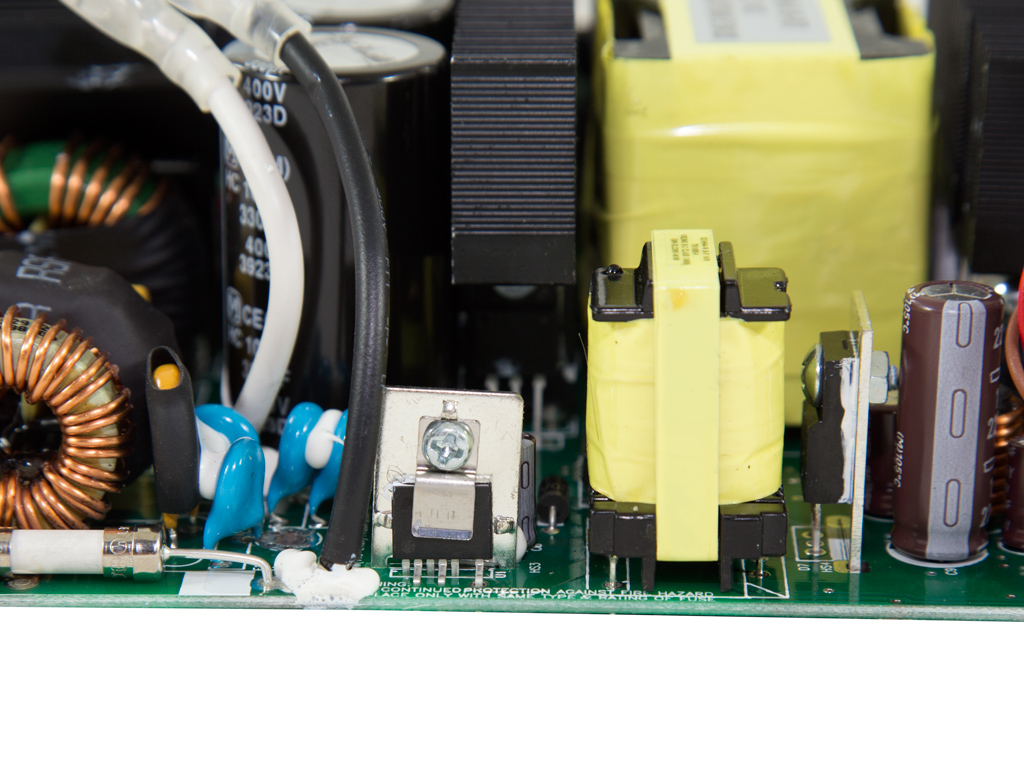
In the APFC, two SPW35N60C3 fets chop the incoming fully rectified signal; the three three bulk caps (400V, 330uF each or 990uF combined, 105°C, HC series, 2000h lifetime) with a rather small combined capacity for a 1.7 kW PSU are by Panasonic/Matsushita, so we expect a pretty low hold-up time. The APFC controller, an ICE2PCS01 IC, is on a vertical PCB. We also found an LM393 voltage comparator on the same PCB. On the main PCB is a CM02X IC that blocks the current through the cap discharge resistor when AC voltage is connected.
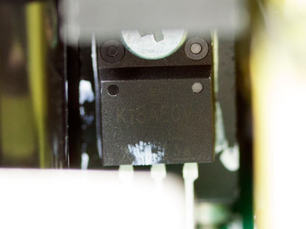
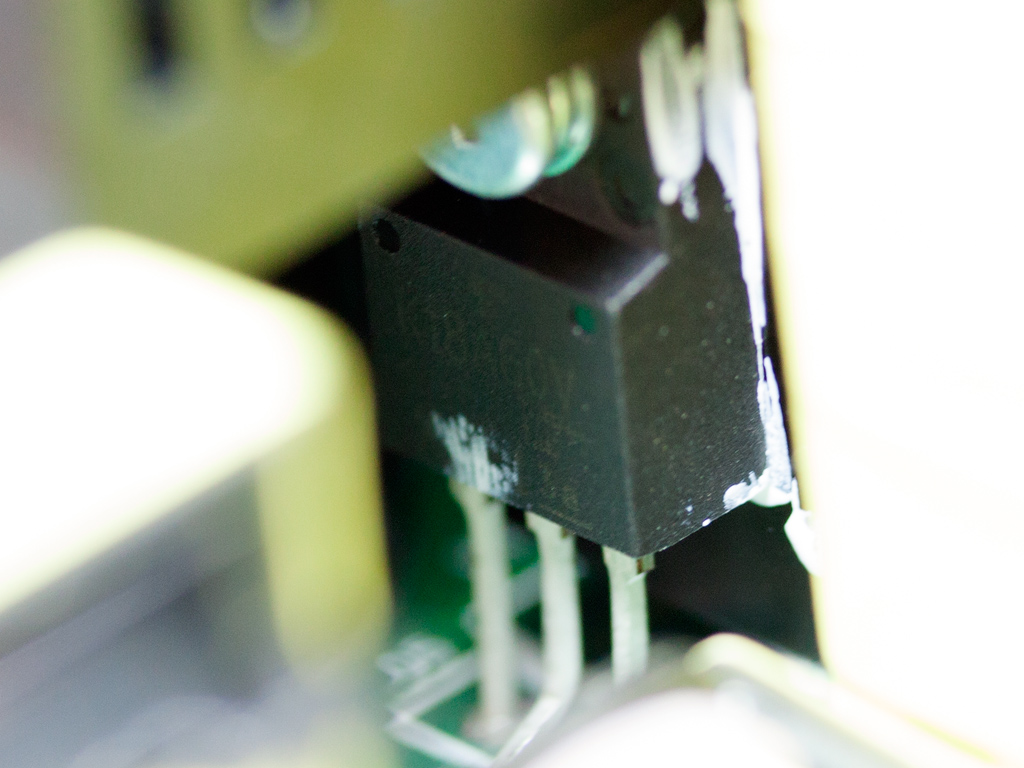
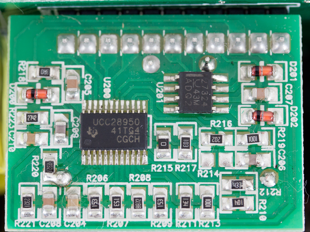
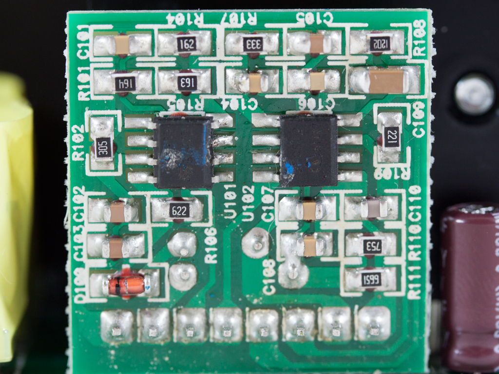
The main choppers are installed in a full bridge topology, and their model number is TK18A60V (Toshiba). On a small daughter-board resides a UCC28950 IC, the main switchers' controller, and the other IC on this board is a UCC27324, a high-speed, low-side power mosfet driver.
The main transformer looks small for the unit's capacity, but its high density should allow it to cope with the task.
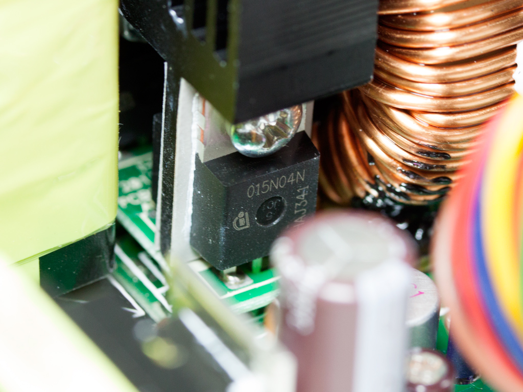
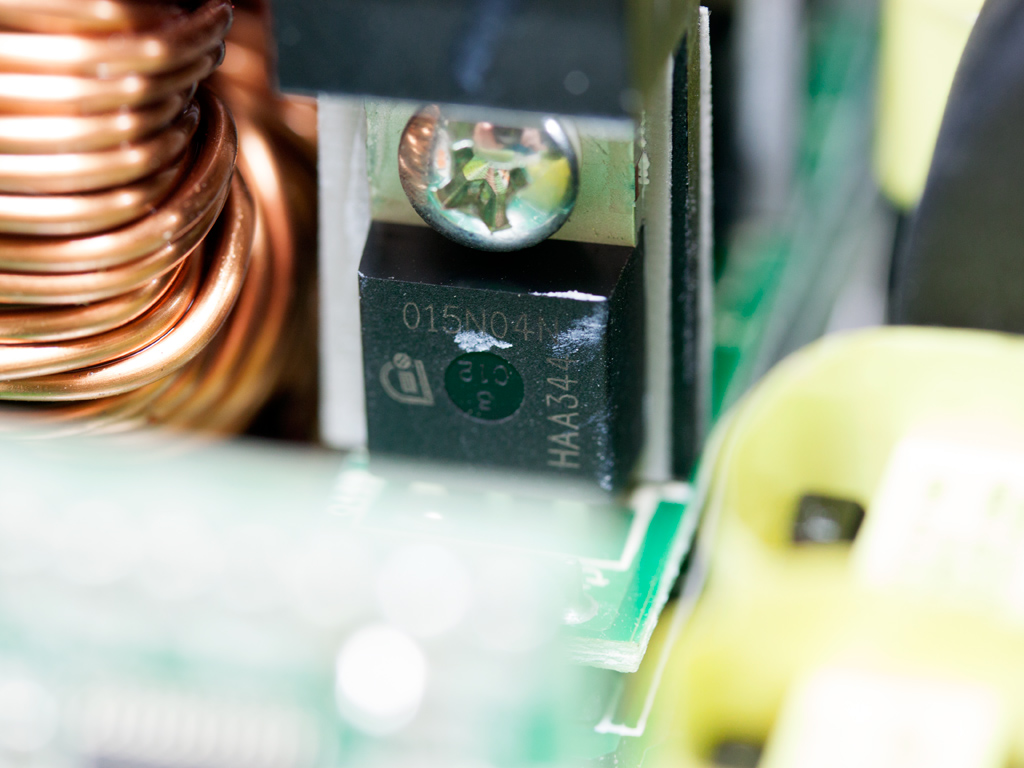
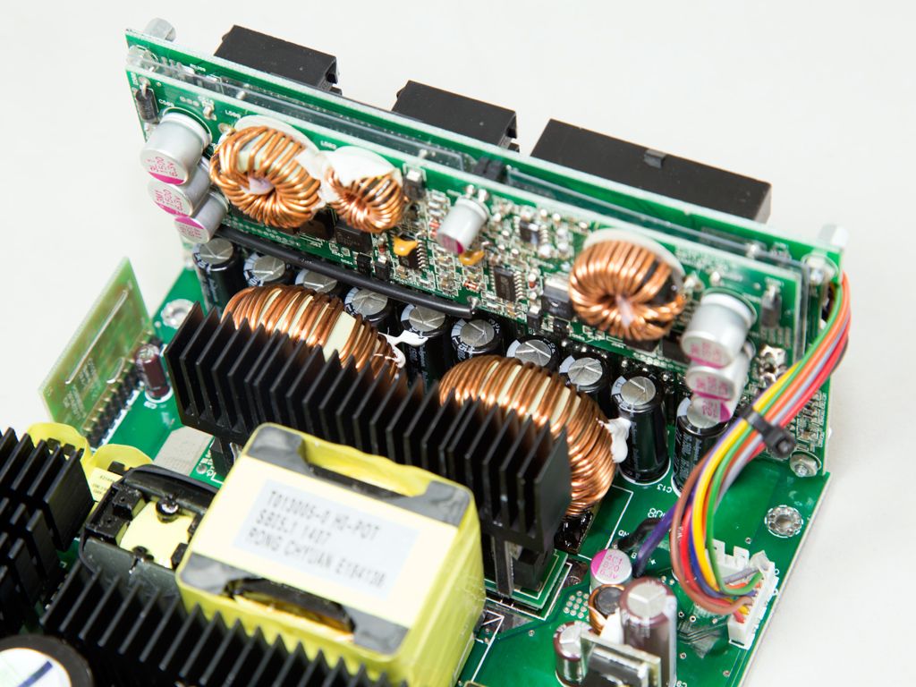
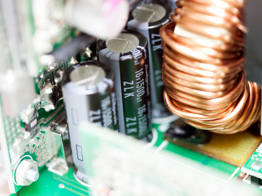
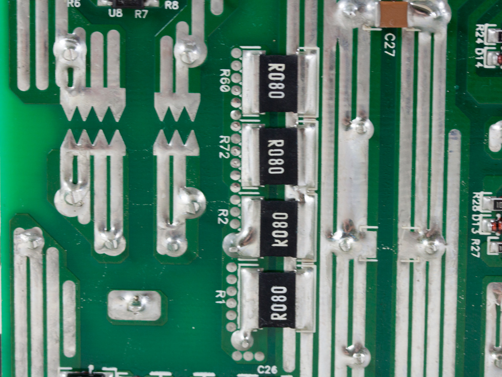
The secondary heatsink holds eight IPP015N04N fets that regulate +12V. Two large toroidal chokes and ten Rubycon caps (16V, 1500μF, 105°C, ZLK series) behind these filter this rail.
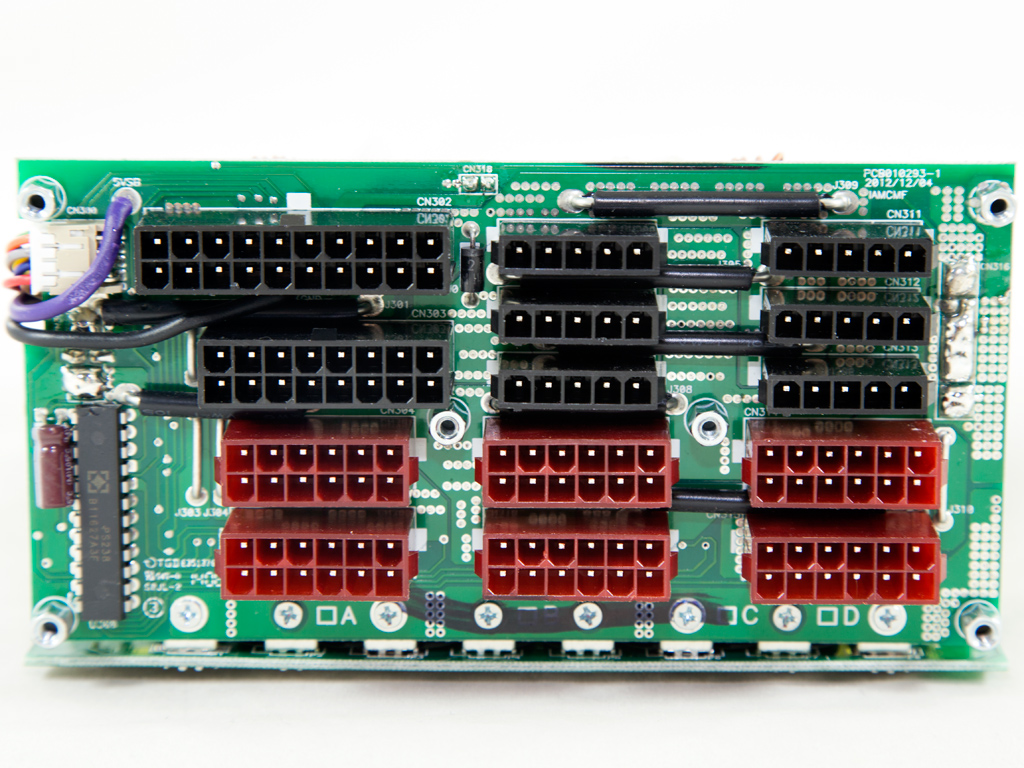
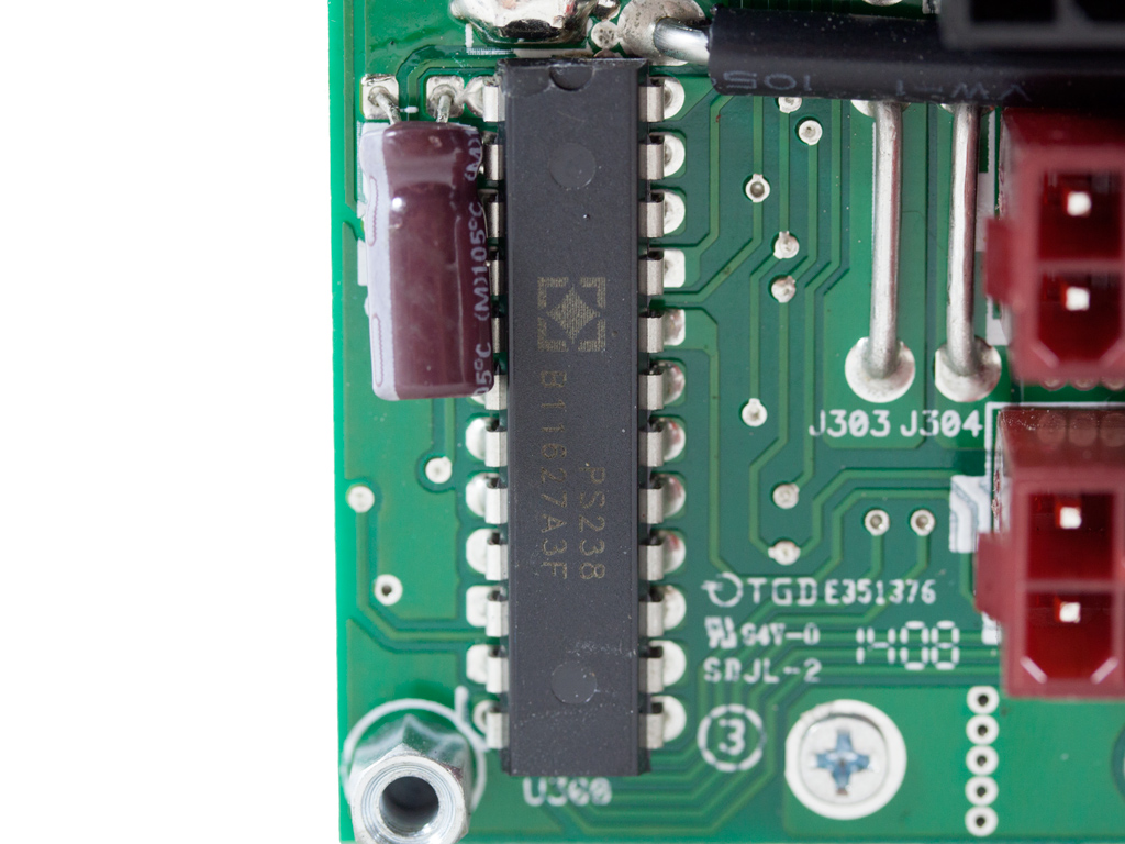
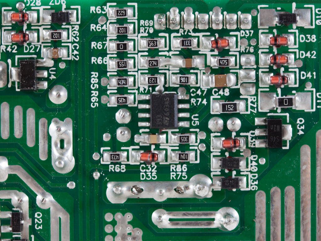
The +12V rail is transferred to the modular PCB and the smaller PCB right behind it, with VRMs, through several bus bars. This particular approach manages to avoid the use of wires, which minimizes voltage drops, especially at high loads. The shunt resistors used by the OCP are soldered to the modular PCB's solder side. On front, to the left, is the protections IC, a PS238 that provides OCP for up to six +12V channels, and the unit comes with just as many virtual rails.
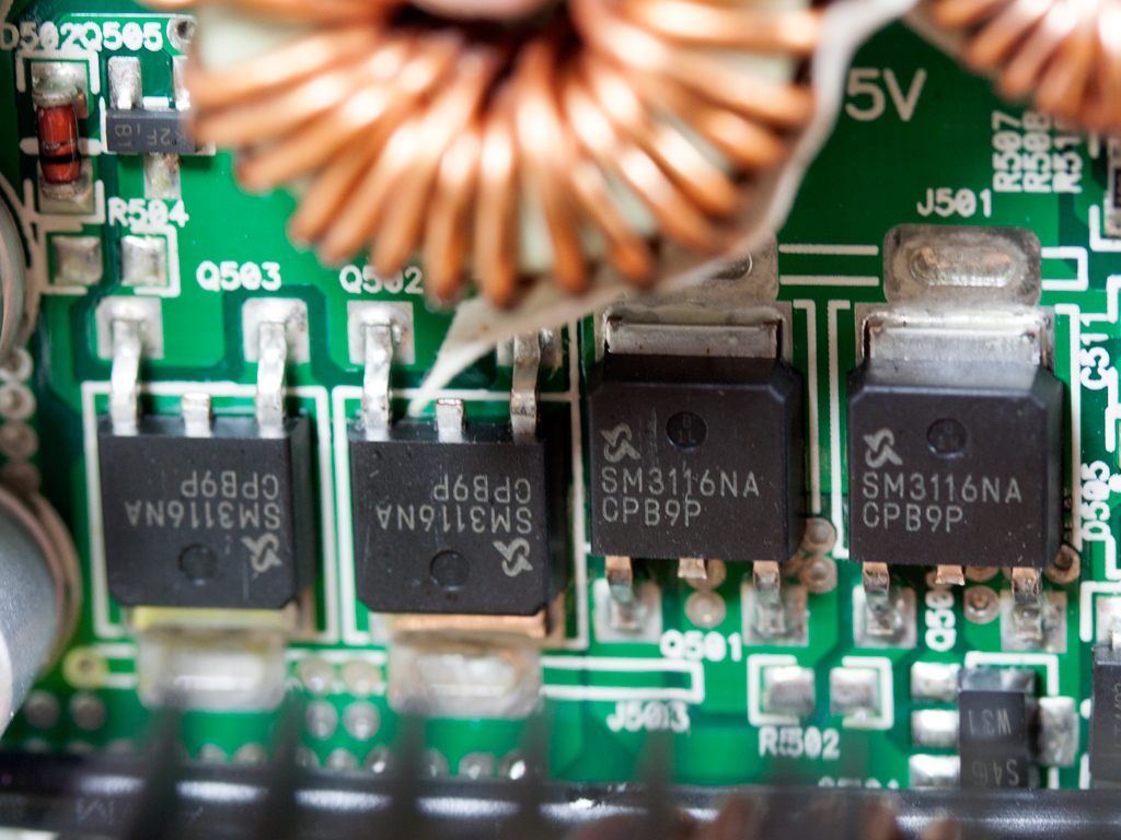
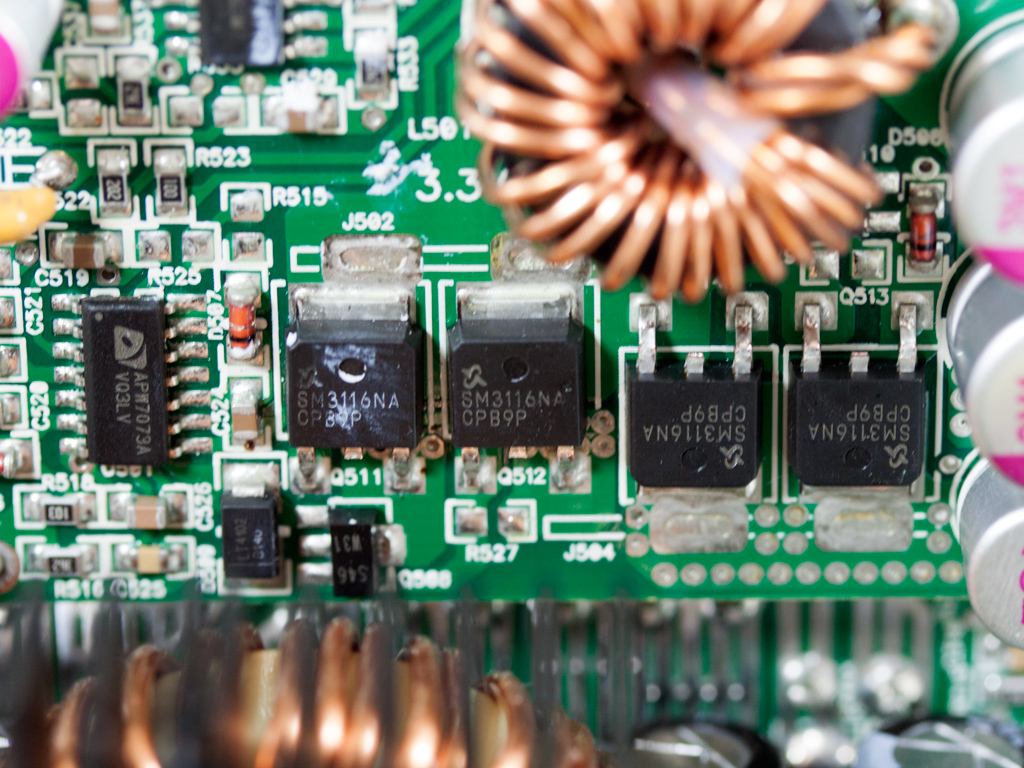
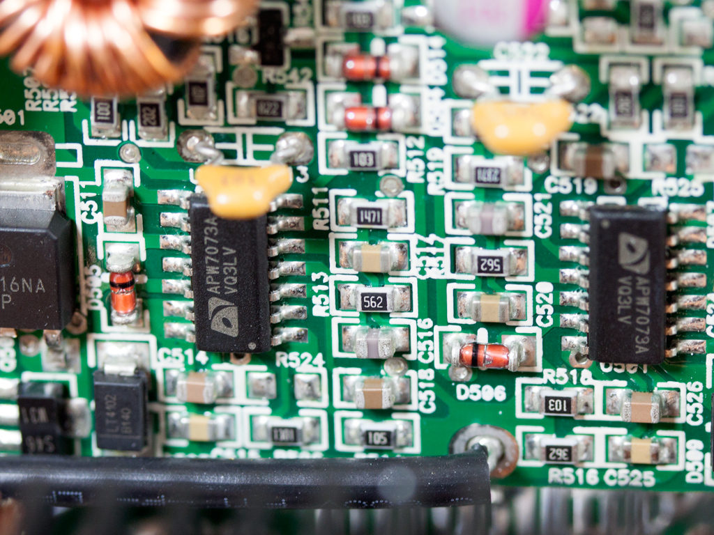
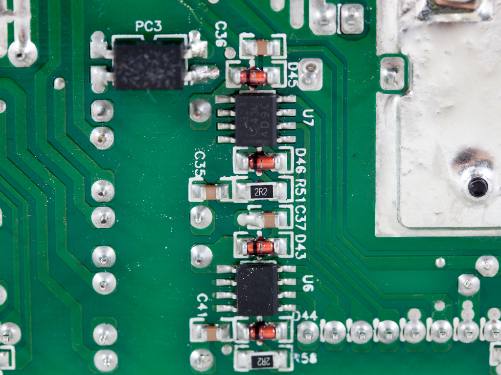
To restrict energy losses, both VRMs responsible for the minor rails are installed very close to the modular PCB, on a smaller PCB right behind it. Each VRM comes with an APW7073 PWM controller, and four APM2556N fets are used, while the filtering polymer caps are by Enesol.
A TOPSwitch-JX TOP265 integrated of-line switcher controls the 5VSB circuit, providing for high efficiency and minimal energy consumption in standby.
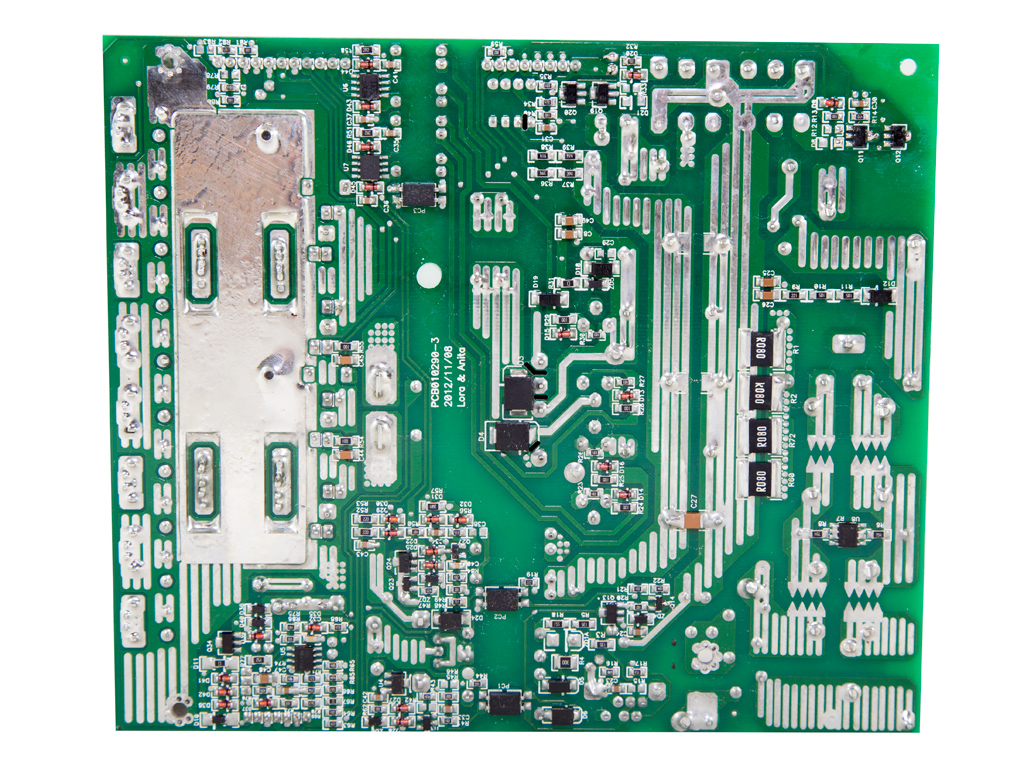
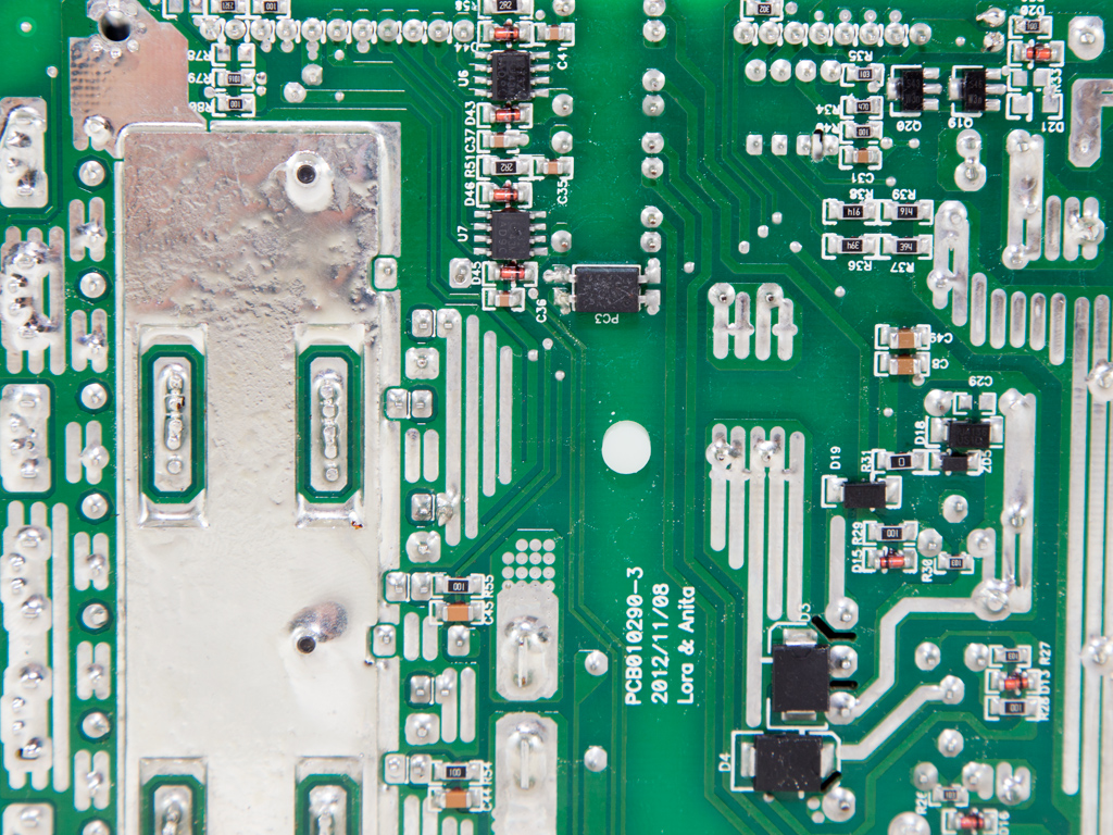
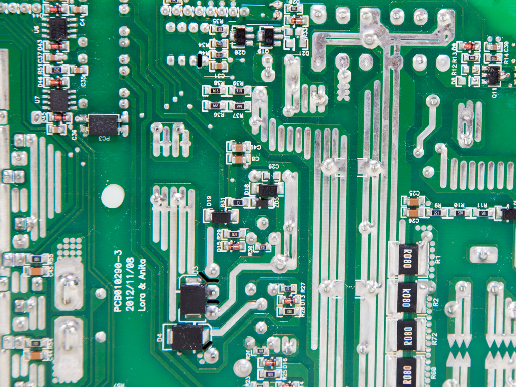
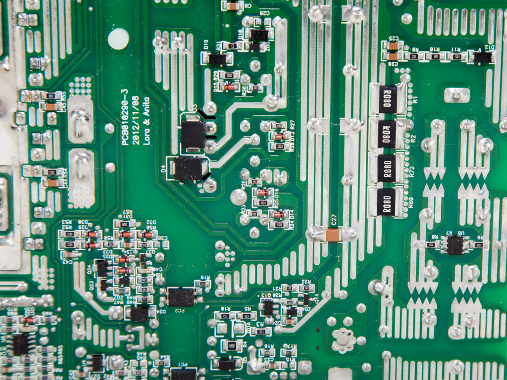
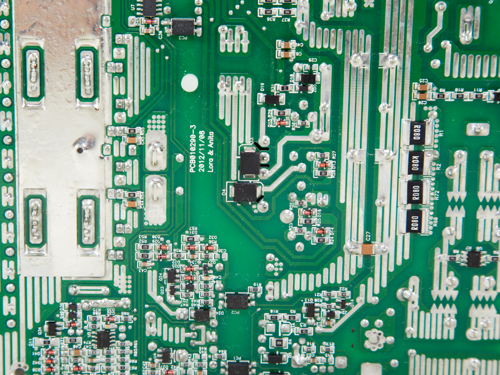
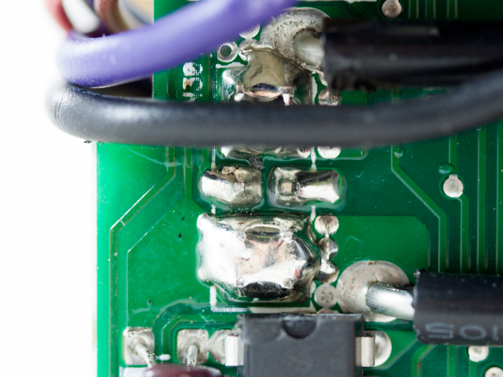
Soldering quality on the solder side of the double-sided PCB is very good. Right below where the +12V rails are rectified is a large copper plate to enhance the PCB's conductivity, which decreases voltage drops, especially with high currents.
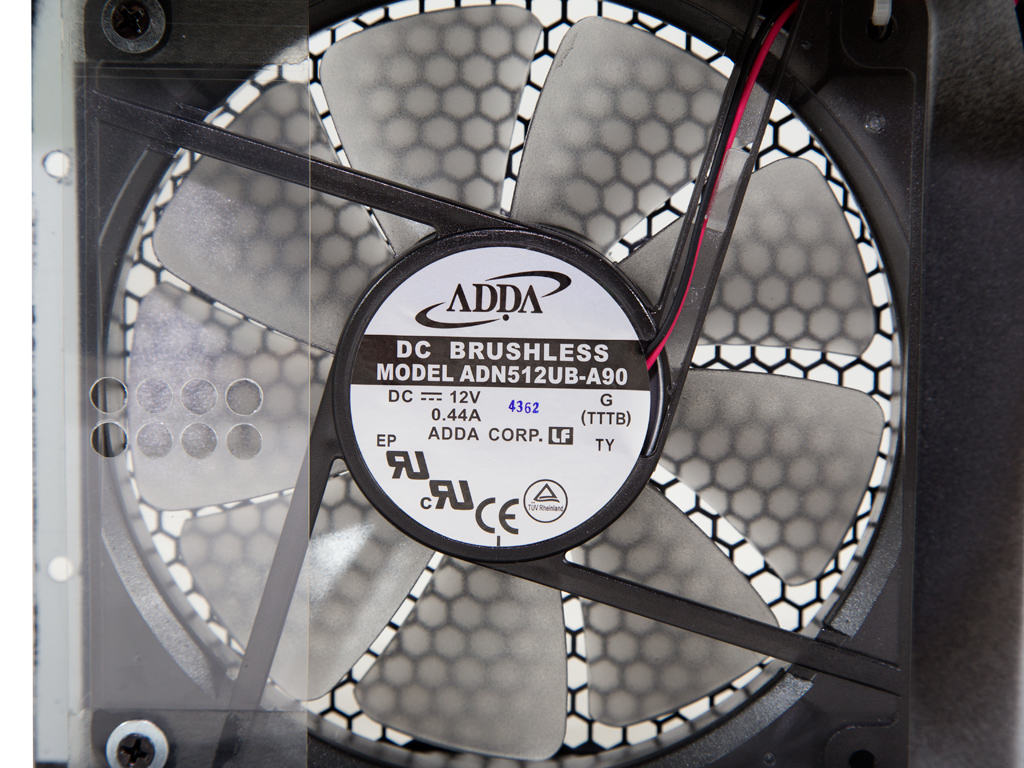
The fan is by Adda, and its model number, ADN512UB-A90, tells us that it is a ball-bearing fan. It is rated for 0.44 A while operating at 12 VDC and is rather noisy at even low RPM, which makes it very loud once it speeds up.
Feb 21st, 2025 08:00 EST
change timezone
Latest GPU Drivers
New Forum Posts
- As we live the age of game remakes, which game you would like to see to have a remake? (293)
- Zotac 5090 Solid disabled ROPs (17)
- It's happening again, melting 12v high pwr connectors (842)
- Get ready to open your wallets people (47)
- Help choosing a GPU (2)
- FlashMyBoard - Automated BIOS Update Tracking & Notification System (10)
- 3D Printer Club (426)
- Nvidia's GPU market share hits 90% in Q4 2024 (gets closer to full monopoly) (405)
- First ever PC build (15)
- What's your latest tech purchase? (23194)
Popular Reviews
- MSI GeForce RTX 5070 Ti Ventus 3X OC Review
- Gigabyte GeForce RTX 5090 Gaming OC Review
- Galax GeForce RTX 5070 Ti 1-Click OC White Review
- ASUS GeForce RTX 5070 Ti TUF OC Review
- Ducky One X Inductive Keyboard Review
- MSI GeForce RTX 5070 Ti Vanguard SOC Review
- MSI GeForce RTX 5070 Ti Gaming Trio OC+ Review
- AMD Ryzen 7 9800X3D Review - The Best Gaming Processor
- MSI MAG Z890 Tomahawk Wi-Fi Review
- NVIDIA GeForce RTX 5080 Founders Edition Review
Controversial News Posts
- AMD Radeon 9070 XT Rumored to Outpace RTX 5070 Ti by Almost 15% (302)
- AMD Plans Aggressive Price Competition with Radeon RX 9000 Series (261)
- AMD is Taking Time with Radeon RX 9000 to Optimize Software and FSR 4 (256)
- AMD Radeon RX 9070 and 9070 XT Listed On Amazon - One Buyer Snags a Unit (244)
- Edward Snowden Lashes Out at NVIDIA Over GeForce RTX 50 Pricing And Value (241)
- AMD Denies Radeon RX 9070 XT $899 USD Starting Price Point Rumors (239)
- New Leak Reveals NVIDIA RTX 5080 Is Slower Than RTX 4090 (215)
- AMD Radeon RX 9070 XT Launch Allegedly Set for March 6 (152)