 7
7
Seasonic X-460FL 460 W Review
Voltage Regulation & Efficiency »A Look Inside
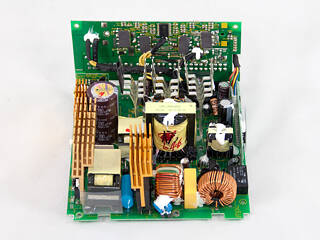
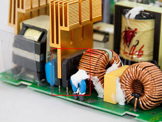
Before reading this page we strongly suggest to take a look at this article, which will help you understand the internal components of a PSU much better.Seasonic used gold colored and pretty small heatsinks in X-460FL, although it is a fanless PSU. Gold efficiency PSUs have very low energy dissipation thus they manage to keep their operating temperatures low.
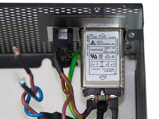
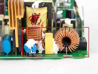
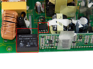
The AC receptacle incorporates a Delta line filter which houses one X and two Y capacitors and two coils. In the main PCB there are more components of the transient/EMI filtering stage, two coils, one X and two Y capacitors and an MOV. There is also a thermistor for inrush current protection and an electromagnetic relay that bypasses it once its job is finished. In the upper right corner of the relay resides the awkwardly soldered standby Quasi-Resonant PWM Controller, an ICE2QR4765.
After the transient filter we find two powerful GBJ1506 bridge rectifiers. Way overspec for the merely 460W of the PSU. In the APFC three mosfets (SPP24N60C3) and a STPSC806D boost diode are used. The smoothing/reservoir capacitor is provided by Nippon Chemi-Con and is rated at 105°C, 420V, 390μF. The APFC is controlled by an NC1564 IC and the LLC resonant controller is a CM6901. This controller operates the primary switches in PWM mode at light loads and in FM mode at higher loads. Finally two 26NM60N are the primary switches.
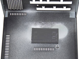
In the secondary side synchronous design is utilized and the four mosfets (IPD031N06L) that regulate +12V are located on the solder side of the main PCB. Although we comment on soldering quality later, in a separate paragraph, we should note here that there are some ugly soldering jobs around these mosfets. Continuing the secondary description, the afore-mentioned mosfets are cooled passively by the casing through a thermal pad and also three heatsinks on the other side of the main PCB are helping. The minor rails are generated through two VRMs (Voltage Regulation Modules or DC-DC converters) that are located on the modular panel, for minimized energy losses. The main PWM controller of the two VRMs is an APW7159 and for each output there are four IPD060N03L mosfets. In the secondary side a few electrolytic and many polymer capacitors are used to filter the DC outputs. Almost all are provided from Nippon Chemi Con since we found several Rubycons (e.g. 5VSB filtering is handled by a Rubycon cap).
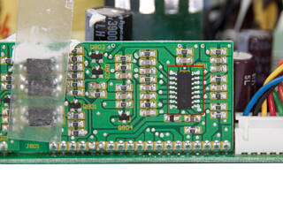
The protection ICs are located on a separate daughter-board at an edge of the main PCB, a PS223 and an LM393 voltage comparator.
Soldering quality on the main PCB was above average but didn't reach the quality levels we expected from a Seasonic product. We found two sloppy hand made solder joints around +12V mosfets and the PCB was dirty possible from soldering flux at some places.
Feb 20th, 2025 03:48 EST
change timezone
Latest GPU Drivers
New Forum Posts
- It's happening again, melting 12v high pwr connectors (800)
- "Is the RX 6800 hotspot value normal ? (13)
- What Router Are You Using For Your Computer (59)
- 5800X3D Undervolting ? (16)
- Lowering idle power on Zen 4? (95)
- Your PC ATM (35244)
- Should I make a thermal maintenance on my GPU? (59)
- TPU's Nostalgic Hardware Club (19967)
- Help with integrated gpu. (46)
- Ryzen Owners Zen Garden (7695)
Popular Reviews
- MSI GeForce RTX 5070 Ti Ventus 3X OC Review - But That MSRP
- Gigabyte GeForce RTX 5090 Gaming OC Review
- Galax GeForce RTX 5070 Ti 1-Click OC White Review
- Ducky One X Inductive Keyboard Review
- AVerMedia X'Tra Go GC515 Review
- AMD Ryzen 7 9800X3D Review - The Best Gaming Processor
- WD Black SN7100 2 TB Review - The New Best SSD
- MSI MAG Z890 Tomahawk Wi-Fi Review
- NVIDIA GeForce RTX 5080 Founders Edition Review
- Kingdom Come Deliverance II Performance Benchmark Review - 35 GPUs Tested
Controversial News Posts
- AMD Radeon 9070 XT Rumored to Outpace RTX 5070 Ti by Almost 15% (302)
- AMD is Taking Time with Radeon RX 9000 to Optimize Software and FSR 4 (256)
- AMD Plans Aggressive Price Competition with Radeon RX 9000 Series (246)
- AMD Radeon RX 9070 and 9070 XT Listed On Amazon - One Buyer Snags a Unit (242)
- Edward Snowden Lashes Out at NVIDIA Over GeForce RTX 50 Pricing And Value (241)
- AMD Denies Radeon RX 9070 XT $899 USD Starting Price Point Rumors (239)
- New Leak Reveals NVIDIA RTX 5080 Is Slower Than RTX 4090 (215)
- AMD's Radeon RX 9070 Launch Faces Pricing Hurdles (175)
