 0
0
Thecus N2310 Review
Software, Quick Installation Guide & Initial Setup »A Look Inside
It's time now to strip this NAS down to discover what components are hidden inside. Taking apart the N2310 is fairly easy, but there is a catch: You not only have to remove the screws at the back as there are also two well-hidden screws underneath its rubber feet at the front. Remove all of these and you can take the plastic bezel out by tugging at it gently. Now apply some pressure toward its solid top and both sides to remove the cover. We, strangely enough, didn't see any warranty stickers.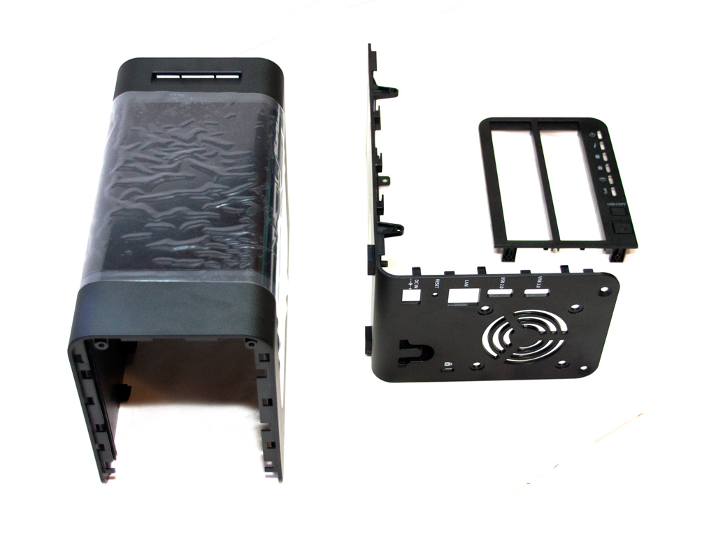
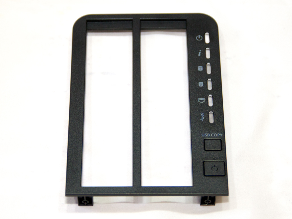
The parts of the plastic enclosure in all their glory.
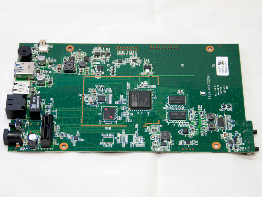
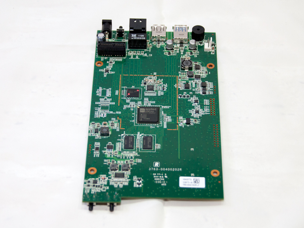
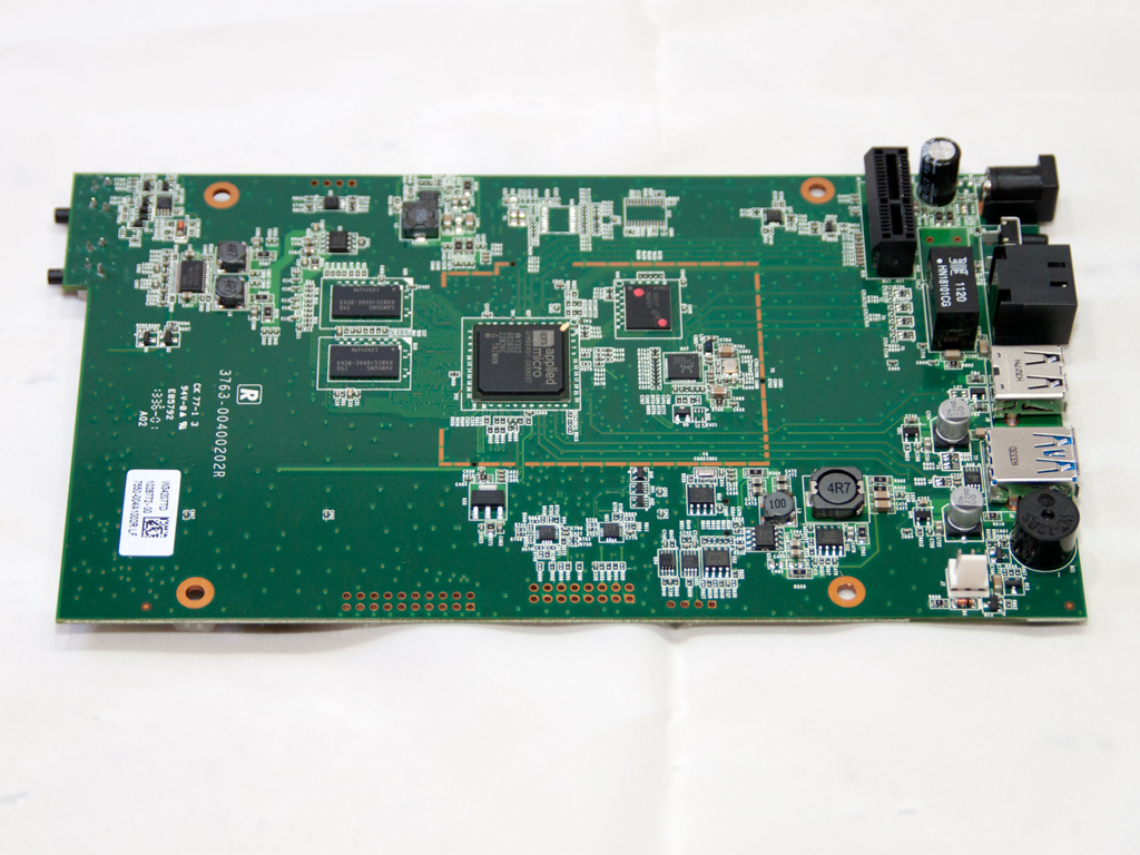
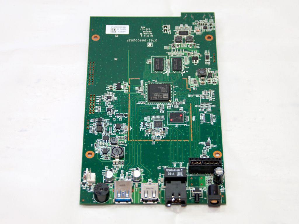
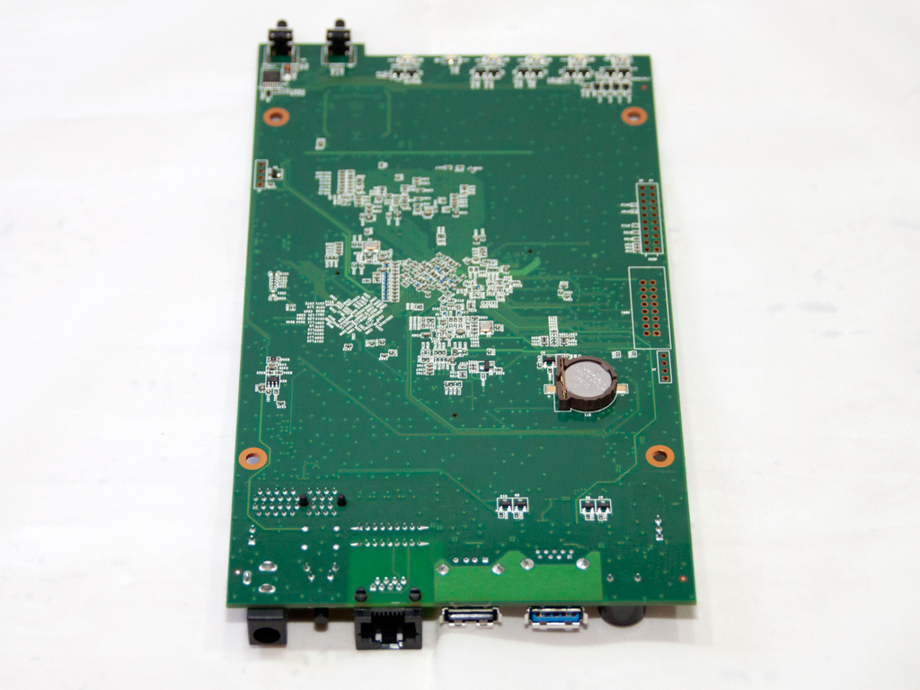
The mainboard is really small but very densely populated, though most of the components it uses are integrated into the SoC.

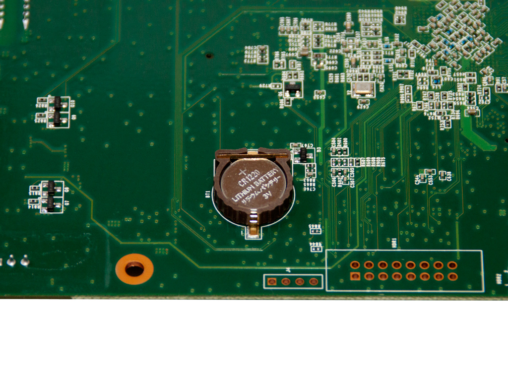
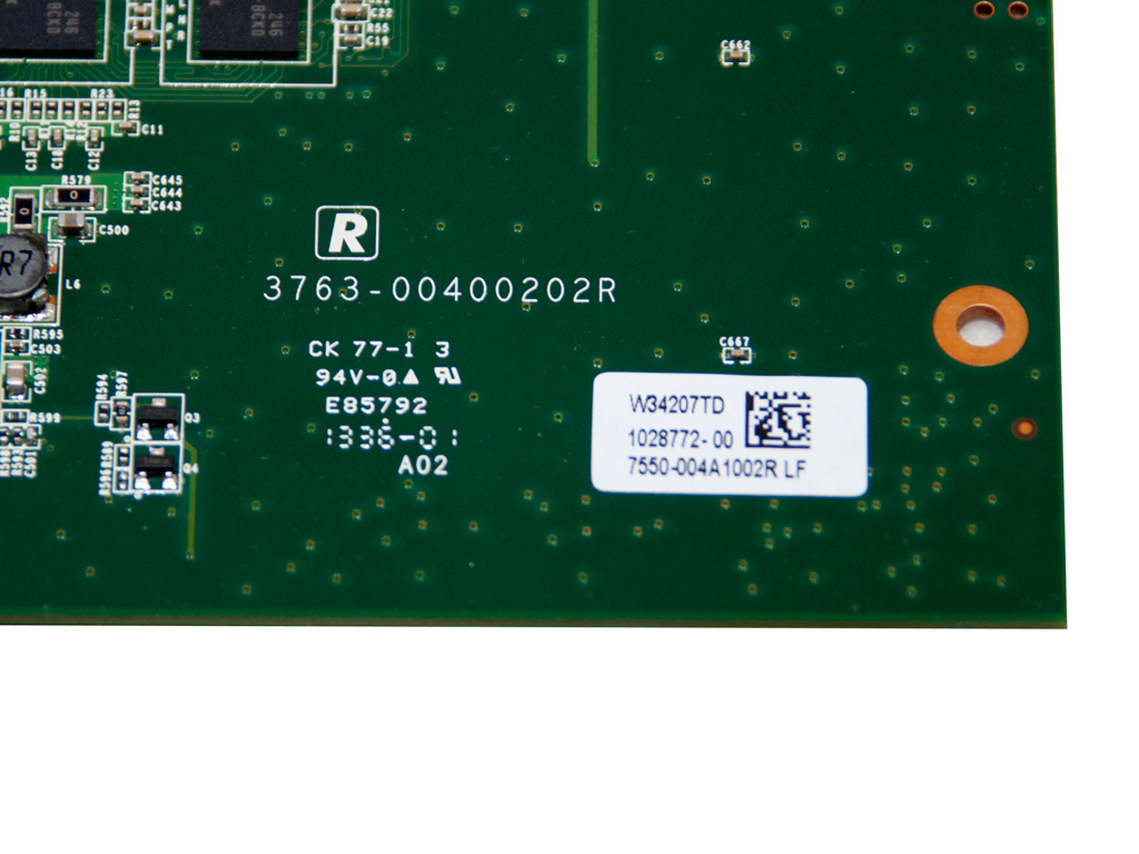
The battery for the BIOS is installed on the solder side of the mainboard.

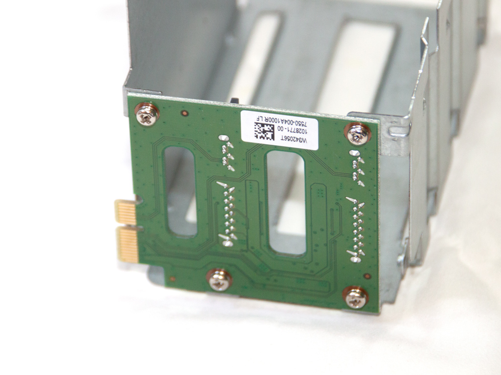
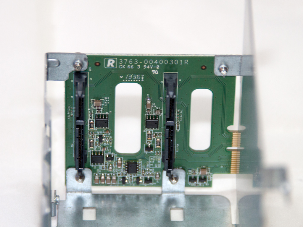
The metal cage holding the HDD rails and the PCIe expansion card with its SATA connectors.
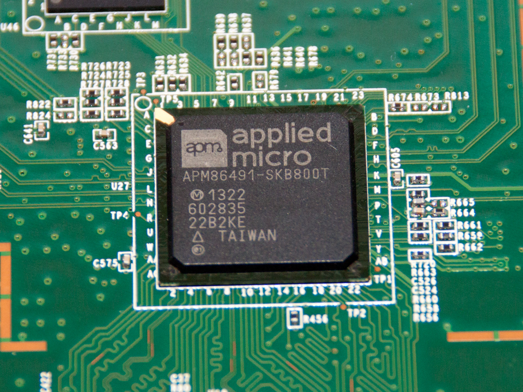
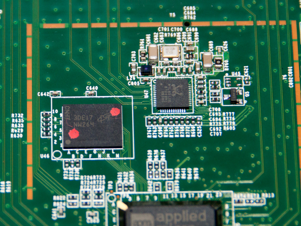
An Applied Micro APM86491 SoC is the brains of this NAS. It can support up to two USB 3.0 ports (there is, however, only one in the N2310), two PCI Express Gen 2 ports, up to two SATAII ports, and two 10/100/1000 Ethernet ports. The Catalina APM86491 PowerPC 465 core features a floating point unit, 32KB L1 I-cache, 32KB D-cache, and 256 KB L2 cache, and its TDP is so low that it doesn't even need a passive heatsink to keep cool.
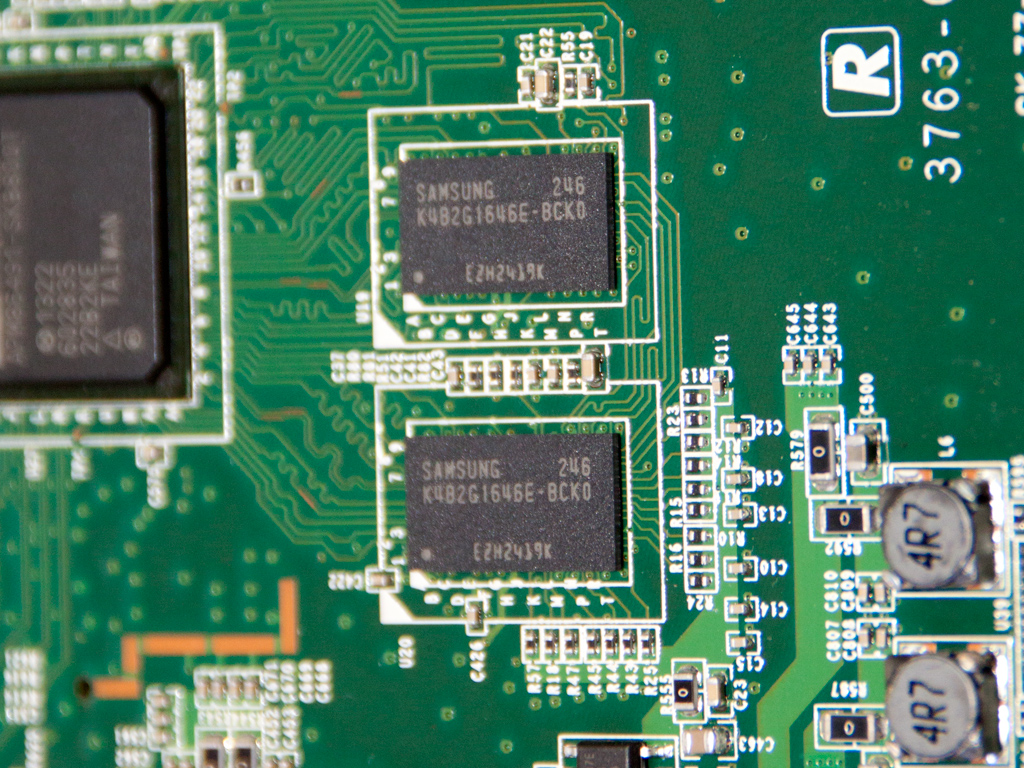
A couple Samsung FGBA K4B2G1646E-BCK0 DDR3 RAM ICs are soldered to the board. Their combined capacity is 512 MB. The same ICs are also used in the Synology DS214Play we have reviewed recently.
The single PCIe slot of the mainboard on which the SATA expansion card is installed.
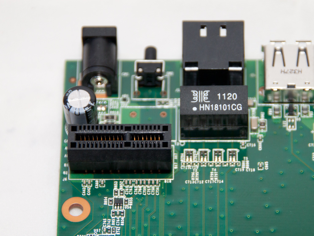
A Realtek RTL8211E gigabit Ethernet controller and the Micron 2Gb x8 ECC NAND Flash Memory the APM86491 SoC uses.
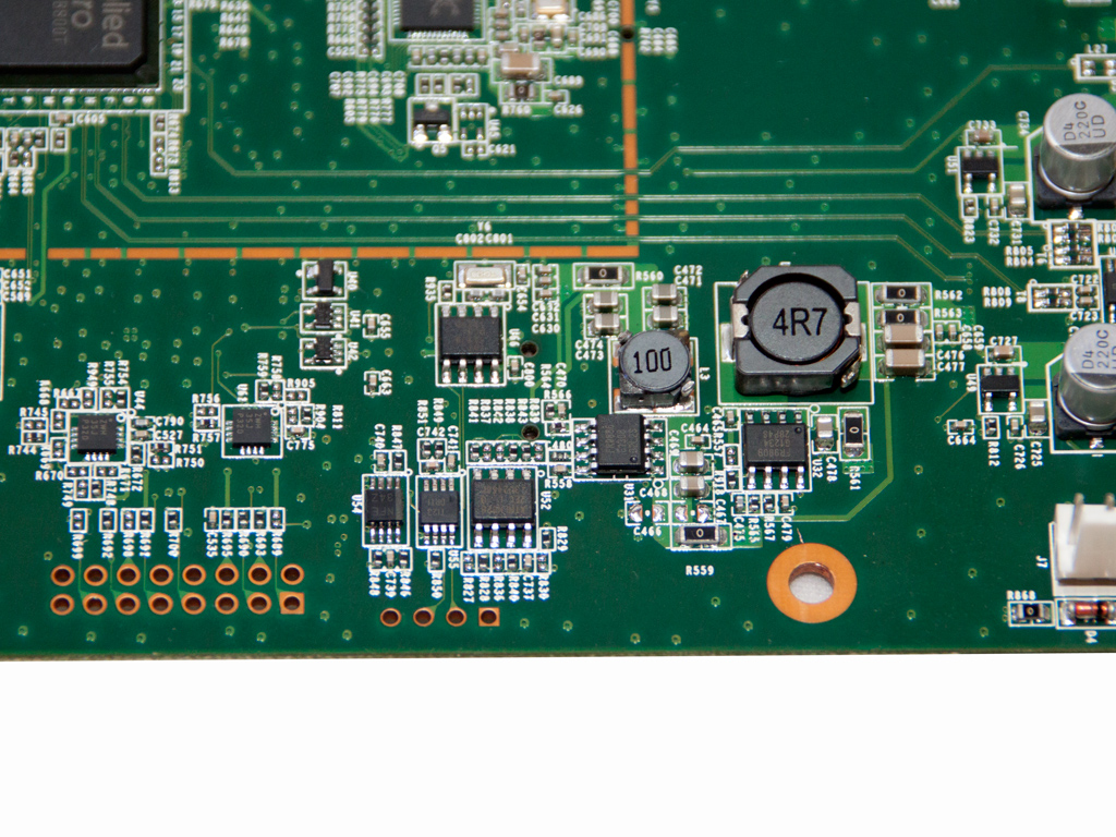
Two of the VRMs (Voltage Regulation Modules) that feed the mainboard's components. The first uses a Fitipower FR9806 step-down DC/DC converter with up to 3 A continuous current output, and the second uses an FR9809 that can deliver up to 5 A current.
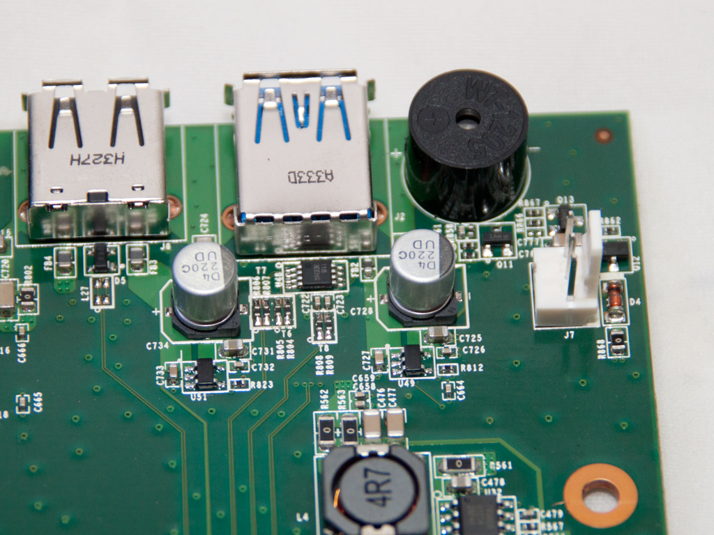
The buzzer is next to the fan header, and there are two polymer caps by Nichicon in the same area.
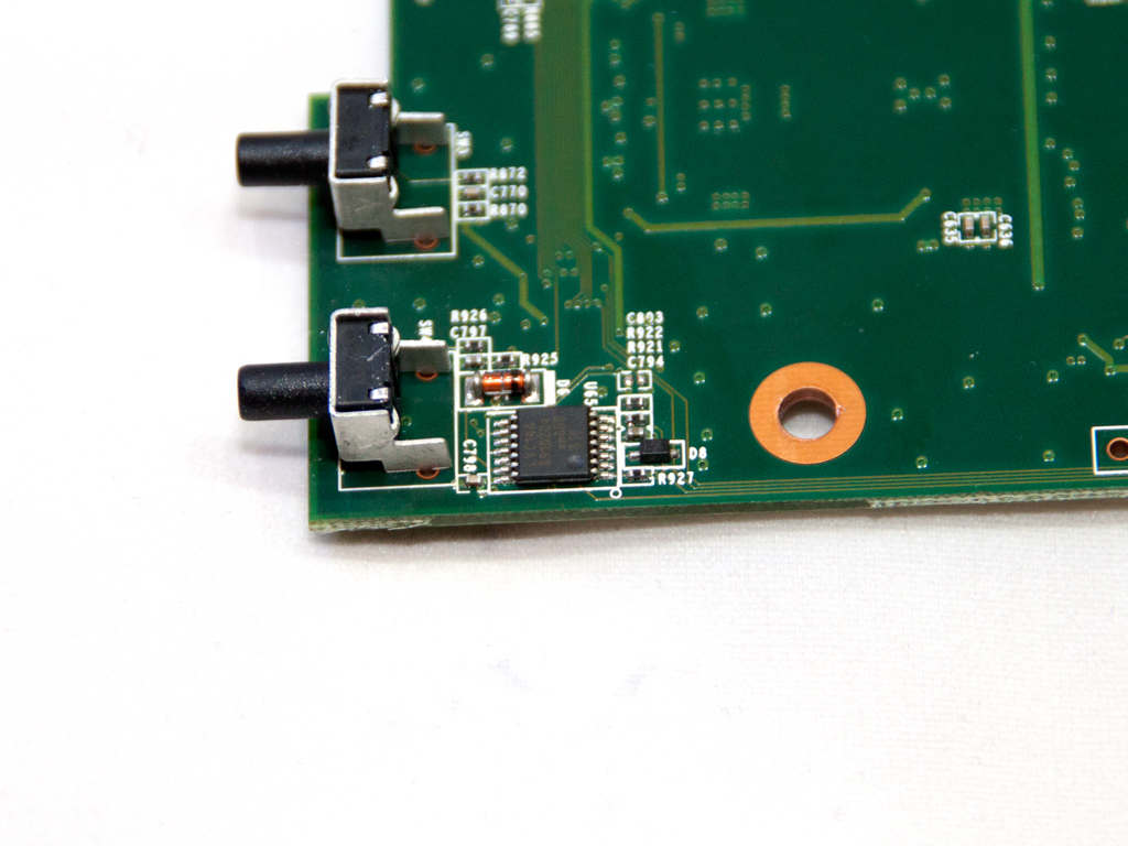
We spotted this IC on the solder side of the main PCB. It is a TI LVC14A HEX Schmitt-Trigger. An active circuit that converts an analog input signal into a digital output signal, it is called a "trigger" because its output retains its value until the input changes sufficiently to trigger a change. You can read more about it here.
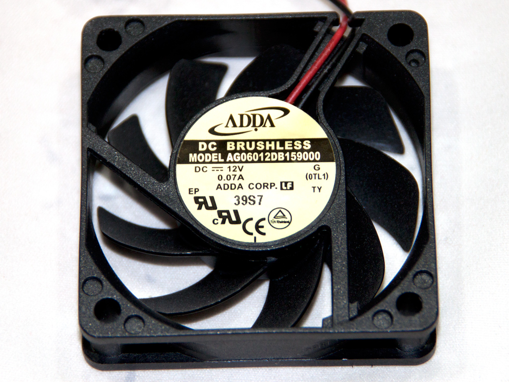
The cooling fan is by ADDA, and its model number is AG06012DB159000 (12 V, 60 mm diameter, 0.07 A). It uses double ball-bearings and is a low-speed fan. It isn't noisy while operating normally but picks up in noise at close to full speed.
Feb 24th, 2025 07:00 EST
change timezone
Latest GPU Drivers
New Forum Posts
- Help choose M.2 Key E Wifi card (0)
- It's happening again, melting 12v high pwr connectors (908)
- Throw Noctua alternatives at me pls (3)
- RDNA4 Prediction Time Part Deux!!! (42)
- [Testers-Needed] Converting Any Realtek Ethernet to Intel Killer Ethernet chip (87)
- [Intel AX1xx/AX2xx/AX4xx/AX16xx/BE2xx/BE17xx] Intel Modded Wi-Fi Driver with Intel® Killer™ Features (277)
- Monitor Battle! Help me choose between two contenders (42)
- Warning about DOCP (18)
- help me find the right bios for my his RX580 Iceq2 X 8Gb (6)
- mV boost option greyed out/ CPU Cache isn't separated by P and E/Cinebench Crashing even with no undervolt (1)
Popular Reviews
- ASUS GeForce RTX 5070 Ti TUF OC Review
- MSI GeForce RTX 5070 Ti Ventus 3X OC Review
- darkFlash DY470 Review
- MSI GeForce RTX 5070 Ti Vanguard SOC Review
- MSI GeForce RTX 5070 Ti Gaming Trio OC+ Review
- Galax GeForce RTX 5070 Ti 1-Click OC White Review
- Palit GeForce RTX 5070 Ti GameRock OC Review
- Fantech Aria II Pro Review
- Gigabyte GeForce RTX 5090 Gaming OC Review
- AMD Ryzen 7 9800X3D Review - The Best Gaming Processor
Controversial News Posts
- NVIDIA GeForce RTX 5090 Spotted with Missing ROPs, NVIDIA Confirms the Issue, Multiple Vendors Affected, RTX 5070 Ti, Too (458)
- AMD Radeon 9070 XT Rumored to Outpace RTX 5070 Ti by Almost 15% (304)
- AMD Plans Aggressive Price Competition with Radeon RX 9000 Series (271)
- AMD Radeon RX 9070 and 9070 XT Listed On Amazon - One Buyer Snags a Unit (247)
- Edward Snowden Lashes Out at NVIDIA Over GeForce RTX 50 Pricing And Value (241)
- AMD Denies Radeon RX 9070 XT $899 USD Starting Price Point Rumors (239)
- NVIDIA Investigates GeForce RTX 50 Series "Blackwell" Black Screen and BSOD Issues (236)
- New Leak Reveals NVIDIA RTX 5080 Is Slower Than RTX 4090 (215)