 5
5
ZSA Moonlander Ergonomic Split Keyboard Review
Software »Disassembly
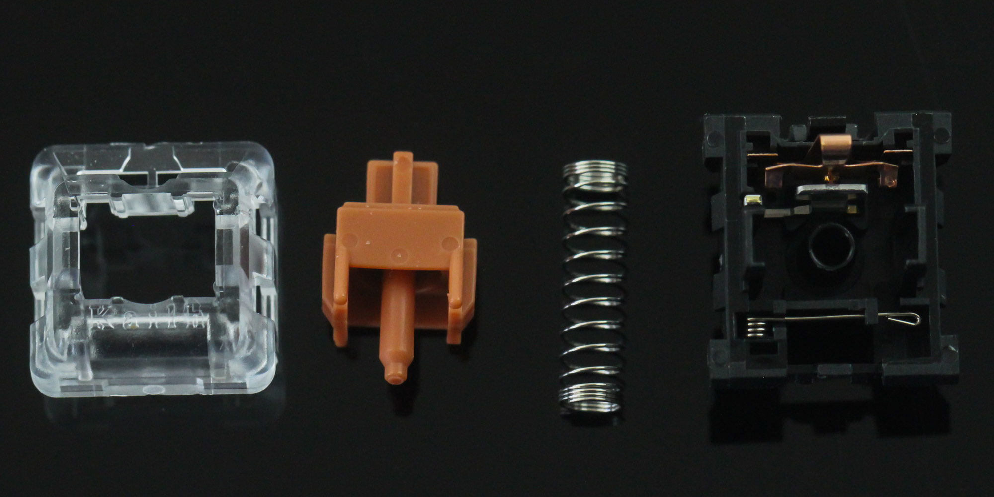
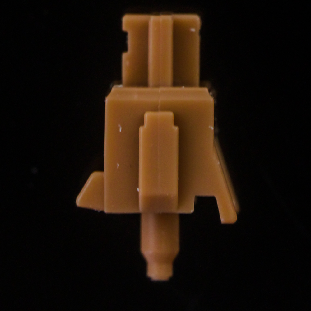
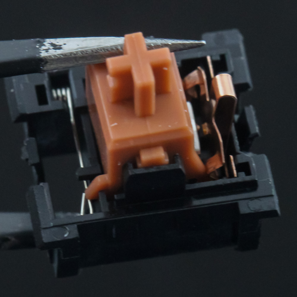
Given we have hot-swappable switches, I thought it best to begin the disassembly section by taking one of the switches apart to see how it ticks inside. The Kailh Bronze consists of a similar set of components as any other Cherry MX-style mechanical switch, at least to a degree. You have the translucent top we saw before, the stem/slider itself, a relatively short regular, coiled spring, and the switch housing that has the metal leaves for contact and actuation as the stem travels down. But we then see something different going on for the tactile and clicky feedback, and Kailh has adopted the click bar mechanism we recently saw with its BOX switches. This allows for decoupled feedback from actuation, as well as a very satisfying feedback mechanism.
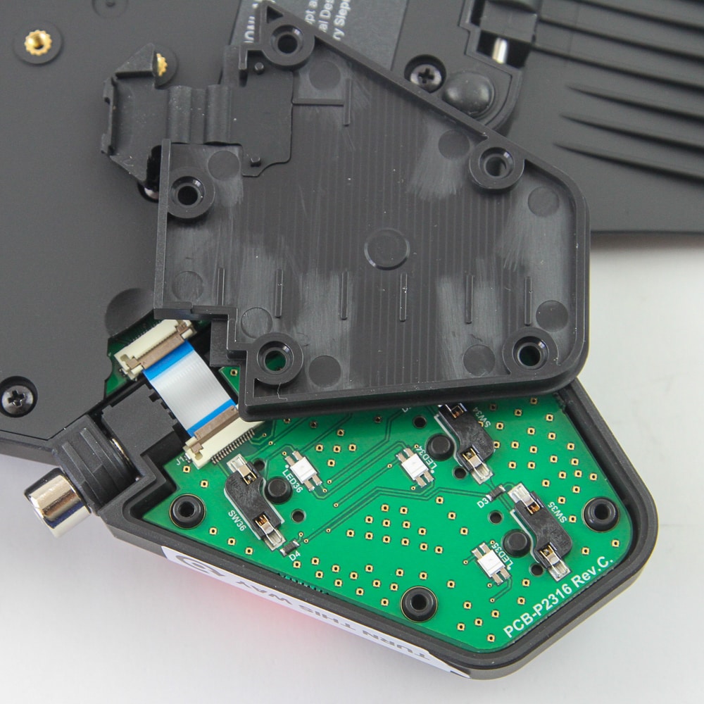
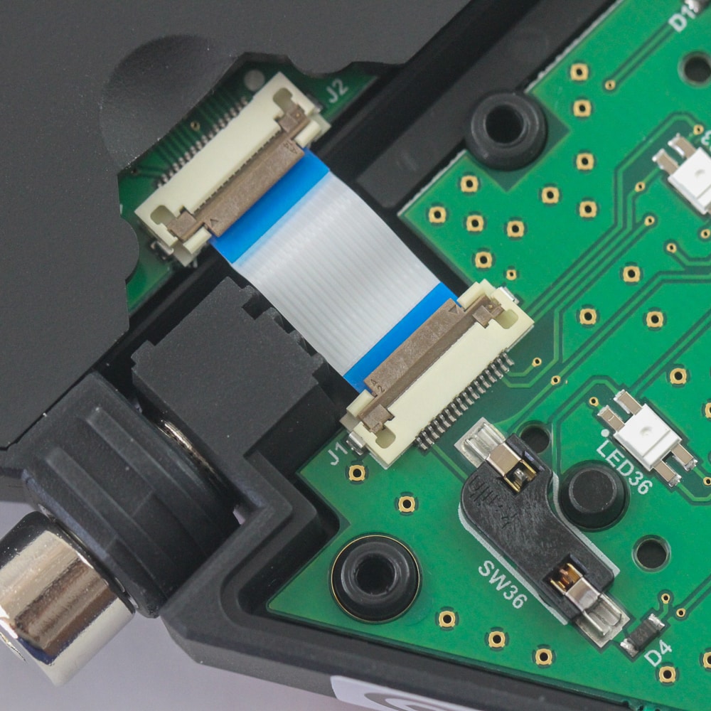
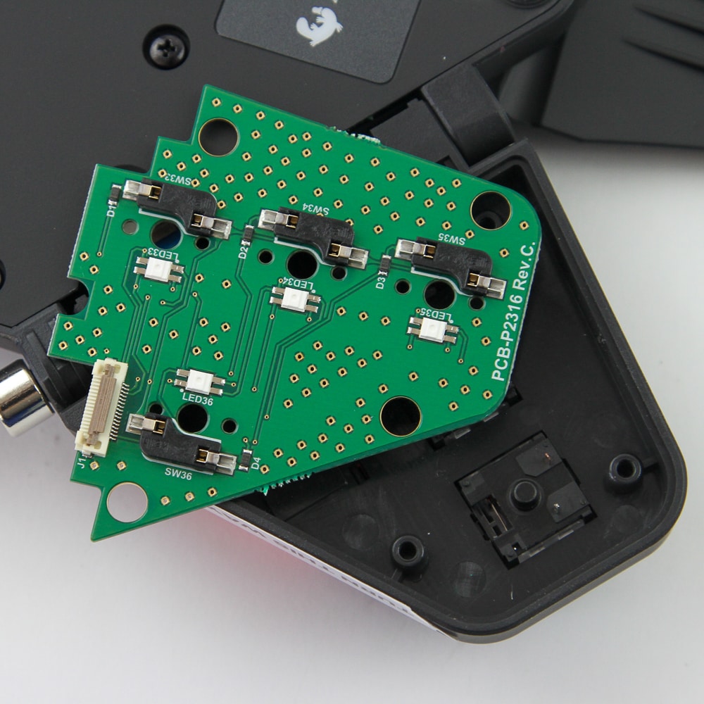
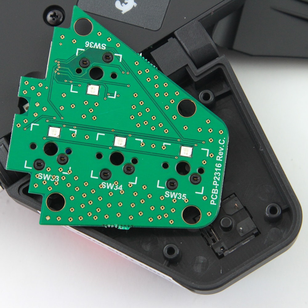
Each half contains two PCBs, of which the smaller one is for the thumb cluster module itself. There are five Phillips-head screws on the back, removing which you can lift up the plastic cover to expose the PCB. There really is not much to see here, but to be sure, disconnect the ribbon cable connecting this daughter PCB to the primary one. This is the left half being dissected, but this section is similar to the right half. Once done, lift up the PCB with its shaped design to fit the module case to see the four hot-swap switch sockets in more detail.
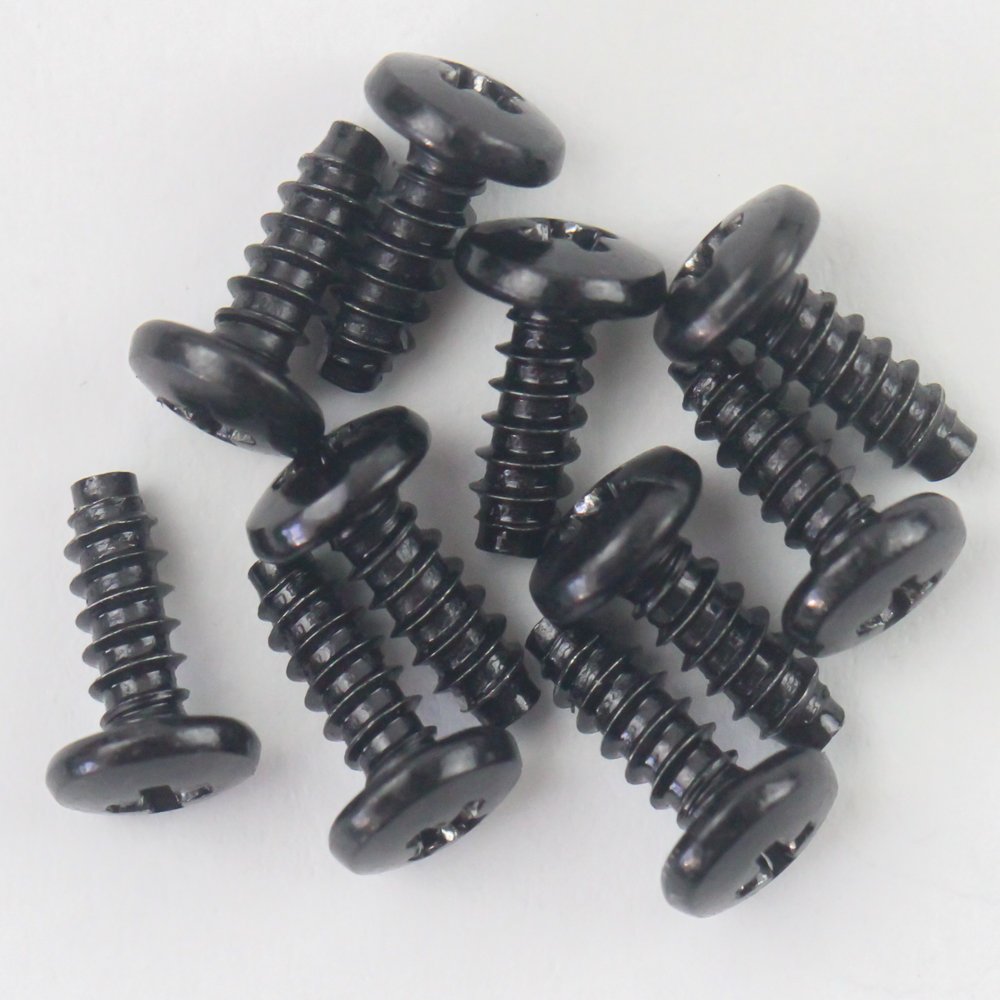
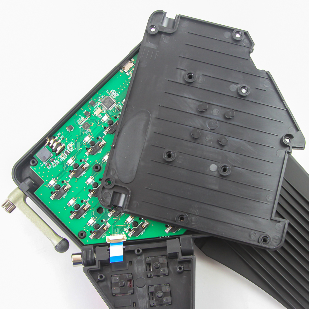
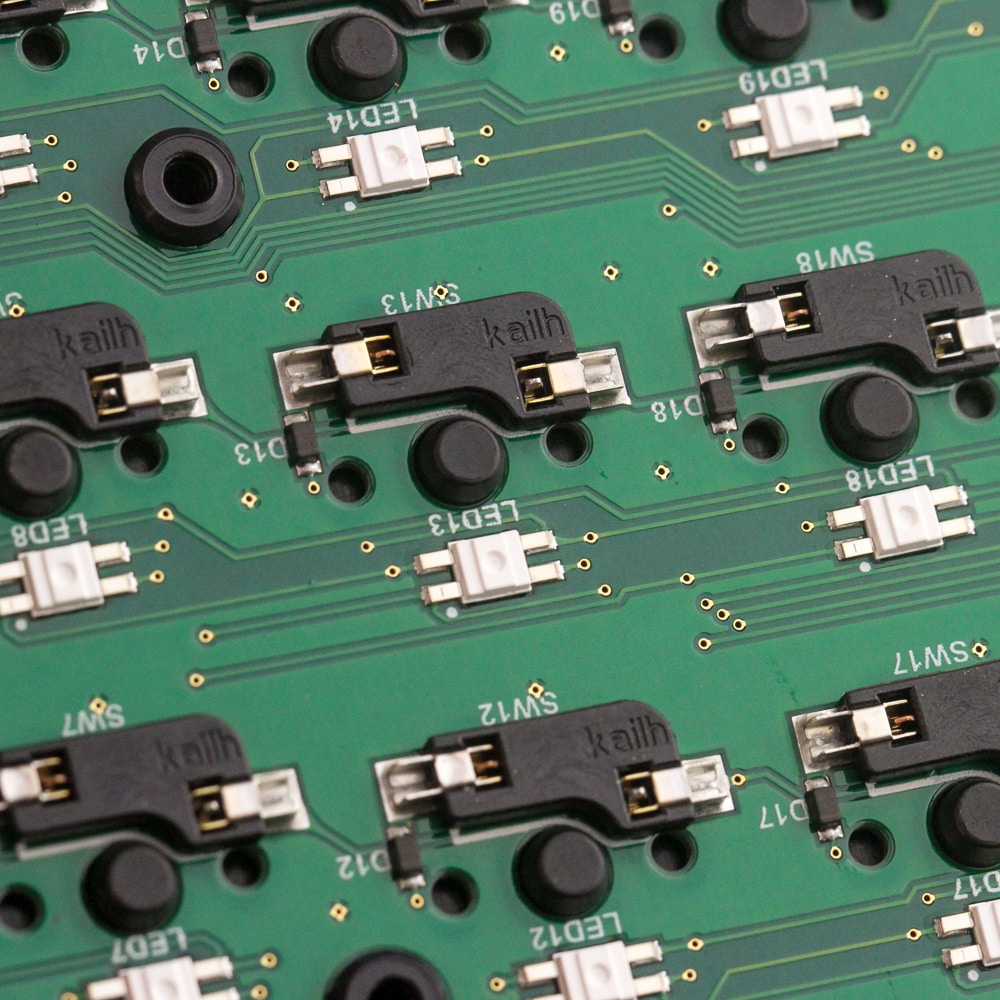
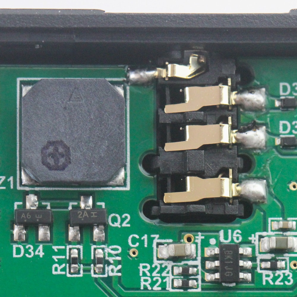
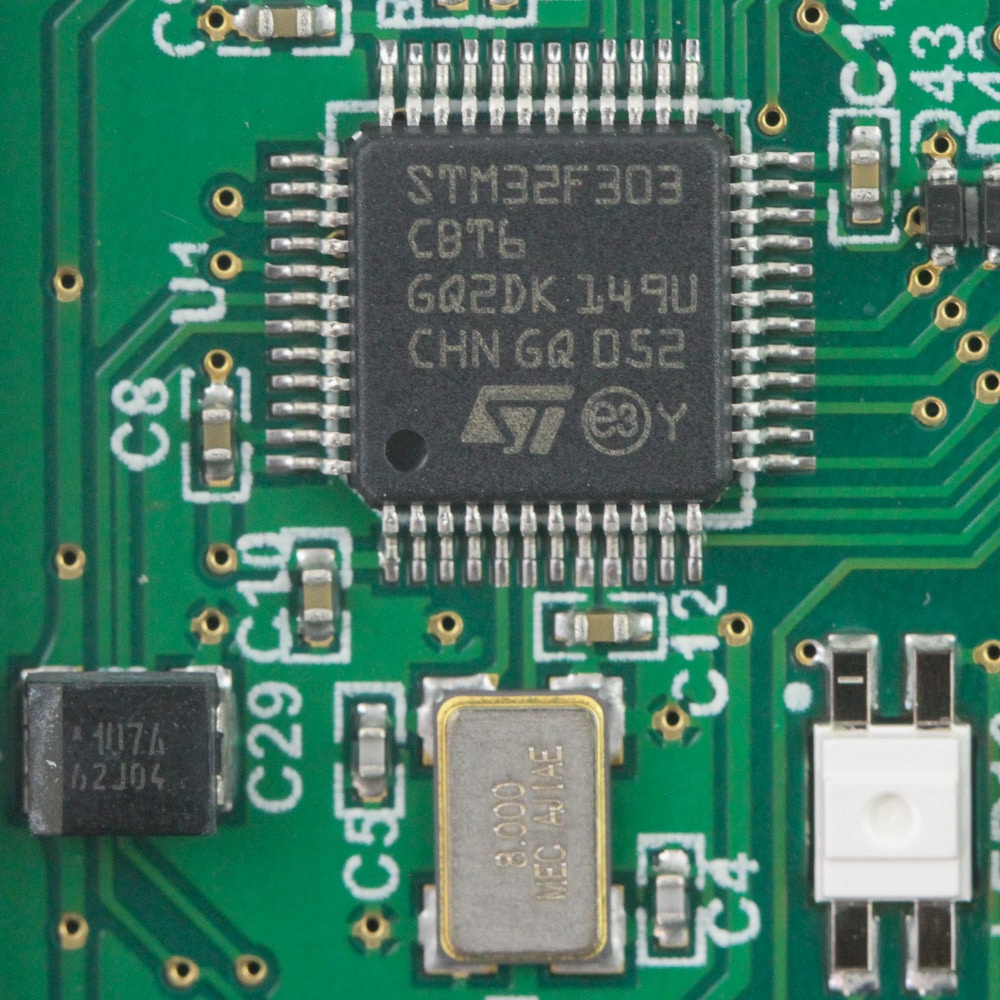

The primary PCB on the left half needs ten of the same screws to be removed for better access, and be careful when lifting the bottom case panel up since it is fairly snug. This panel has several raised stripes which are specifically there to support the switch sockets themselves. You can also lift the PCB out completely, but it has even less give here, so I did not bother, especially with access to the primary components. We do see the use of Kailh hot-swap switch sockets, which is fitting with these Kailh switches on my sample, and there is a small beeping speaker on the PCB for some audio/visual feedback, too. Powering the keyboard is an STMicroelectronics STM32F303C8 Arm Cortex-M4 microcontroller with 64 KB of onboard flash memory and 16 KB of RAM for all the pre-programmed functions. We saw a similar MCU put to good use on the ROG Claymore II, and it is a higher-performance MCU than typically seen on keyboards. As is the norm, all the components are soldered onto a multi-layer PCB. The right half has the speaker but no MCU, which is why the left half can function on its on.
Before we move on, be advised that disassembly may void the warranty and that TechPowerUp is not liable for any damages incurred if you decide to go ahead and do so anyway.
Mar 5th, 2025 13:45 EST
change timezone
Latest GPU Drivers
New Forum Posts
- Will I benefit from changing the thermal pad? (12)
- WD Black or Gold for Gaming (10TB) (25)
- sapphire nitro+ 5700 xt BIOS (1)
- Dell Workstation Owners Club (3293)
- My Rx 6800xt Furmarkt result is good ? (1)
- B550 phantom Gaming ITX/AX bios problem. (16)
- AMD E9260 MXM TYPEA - Trying to flash / confirm original GPU (1)
- Cryptocoin Value and Market Trend Discussion (1642)
- Any plans on adding E Core undervolt support for 13th+ gen? (2)
- Windows 11 General Discussion (5815)
Popular Reviews
- Sapphire Radeon RX 9070 XT Nitro+ Review - Beating NVIDIA
- NVIDIA GeForce RTX 5070 Founders Edition Review
- AMD Radeon RX 9070 Series Technical Deep Dive
- ASUS Radeon RX 9070 TUF OC Review
- EIZO FlexScan EV4340X Review - A Multitasking Powerhouse
- RAWM ES21M Review
- ASUS GeForce RTX 5070 Ti TUF OC Review
- AMD Ryzen 7 9800X3D Review - The Best Gaming Processor
- MSI GeForce RTX 5070 Ti Vanguard SOC Review
- MSI GeForce RTX 5070 Ti Ventus 3X OC Review
Controversial News Posts
- NVIDIA GeForce RTX 50 Cards Spotted with Missing ROPs, NVIDIA Confirms the Issue, Multiple Vendors Affected (513)
- AMD Plans Aggressive Price Competition with Radeon RX 9000 Series (277)
- AMD Radeon RX 9070 and 9070 XT Listed On Amazon - One Buyer Snags a Unit (261)
- AMD Mentions Sub-$700 Pricing for Radeon RX 9070 GPU Series, Looks Like NV Minus $50 Again (248)
- NVIDIA Investigates GeForce RTX 50 Series "Blackwell" Black Screen and BSOD Issues (244)
- AMD RDNA 4 and Radeon RX 9070 Series Unveiled: $549 & $599 (241)
- AMD Radeon RX 9070 and 9070 XT Official Performance Metrics Leaked, +42% 4K Performance Over Radeon RX 7900 GRE (195)
- AMD Radeon RX 9070-series Pricing Leaks Courtesy of MicroCenter (158)