DFI LanParty NF3 VDimm Mod |
|
|
Author: Celemine
Date: 2005-08-20 13:56:01
|
|
Additional hardware Vdimm-Mod
Datasheet of the chip: http://www.semiconductors.philips.com/acrobat/datasheets/LMX58_A_2904_XX532_4.pdf
I already mentioned that there are unofficial, unsupported BIOS versions that feature up to 4V VDimm. Now you'll perhaps ask, "why should I do the hardware VDimm-Mod then?". The answer is simple. As I explained above the board has cold boot problems when running high Vdimm.
The only way to fix this, is doing this easy hardware mod, that makes the board start with the VDimm that you adjusted via potentiometer, even on the first boot. It let's you adjust the VDimm to your liking and most important with much more precision (BIOS only let's you choose VDimm in steps of 0.1V, while you can adjust it in steps of at least 0.01V with the help of the hardware mod). For this mod you can either use a single 100K potentiometer (precision ~6.67K per full turn), or if you wish to have a little more precision, 2x 50K potentiometers (precision ~3.33K per full turn), connected in series, which again gives you a final resistance of 100K. Both ways will work, but it's up to you, to decide which one you like more. :)

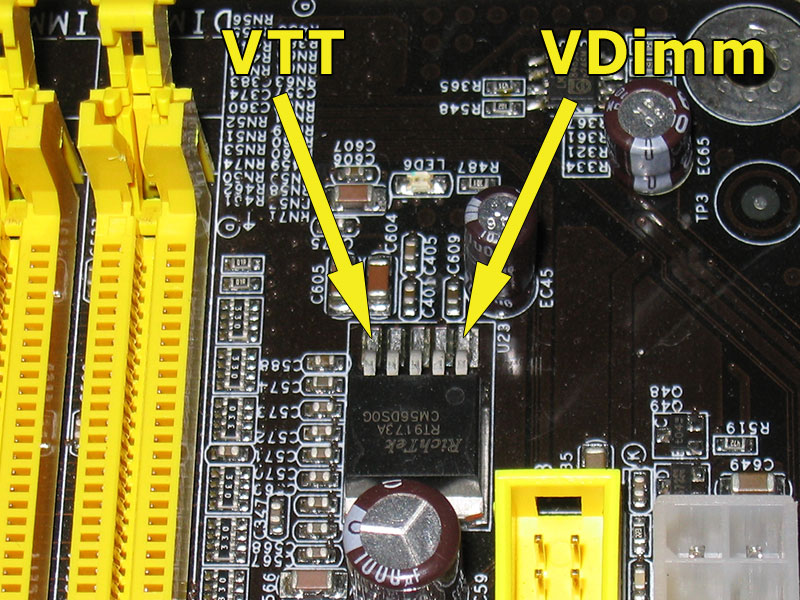
The 100K potentiometer(s) need(s) to be soldered in between pin#3 and pin#8 of the LM358 chip („U28“). Locate the pins according to the datasheet, or just have a look at my pictures and then connect the outer pin of the potentiometer(s) to pin#3 and the middle potentiometer-pin to pin#8 on the LM358 chip. Remember to have the potentiometer(s) set to maximum resistance before powering up your board.
Update:
Had to work on the board again today, as it had started to freak out after another additional mod. While fixing this issue I tried something that I had wanted to try from the beginning. I found out that using Pin#2 and Pin#4(Ground) for the Vdimm-Mod also works great. So you can choose between both methods. Either you use the poti between Pin#3 and #8, or you can also use Pin#2 and #4. The combination #2 and #4 is a little better IMHO, because its accessability is simply better. But in the end, the outcome is the same.

In case you might be irritated because you see three potentiometers connected in series on my pics, don't worry, it'll work perfectly with one or two. I only used three first and then just kept it that way, although two would have been enough.
I did the following additional/optional modifications to my board:
- new chipset heatsink, custom made from an Alpha PAL153U 1U CPU cooler

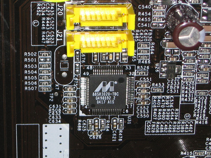
- additional heatsinks for several other chips (VCore-MOSFETs, Marvell PHY chip 88SR3020-TBC, ICS93742AF clock buffer etc.; especially the latter two do indeed get quite hot)


- redid solder-joints for all the capacitors that belong to the VCore- and VDimm-circuits, because they were not perfectly soldered in


Warning:
All modifications are done at your own risk! I am not responsible for any damage caused by the modifications described above! Any hardware modification will definitely void your warranty! Keep that in mind.
Jul 3rd, 2025 03:20 CDT
change timezone
Latest GPU Drivers
New Forum Posts
- Gigabyte graphic cards - TIM gel SLIPPAGE problem (106)
- New build airflow question (3)
- NVIDIA App (42)
- The TPU UK Clubhouse (26547)
- Super-slow WiFi (8)
- HP Zbook 15 G2 GPU Upgrade (7)
- Game Soundtracks You Love (1082)
- How often do you (re)install your OS? (198)
- AMD RX 7000 series GPU Owners' Club (1328)
- Windows 11 General Discussion (6128)
Popular Reviews
- ASUS ROG Crosshair X870E Extreme Review
- Crucial T710 2 TB Review - Record-Breaking Gen 5
- PowerColor ALPHYN AM10 Review
- Sapphire Radeon RX 9060 XT Pulse OC 16 GB Review - An Excellent Choice
- Upcoming Hardware Launches 2025 (Updated May 2025)
- AMD Ryzen 7 9800X3D Review - The Best Gaming Processor
- AVerMedia CamStream 4K Review
- Sapphire Radeon RX 9070 XT Nitro+ Review - Beating NVIDIA
- NVIDIA GeForce RTX 5060 8 GB Review
- AMD Ryzen 9 9950X3D Review - Great for Gaming and Productivity
TPU on YouTube
Controversial News Posts
- Intel's Core Ultra 7 265K and 265KF CPUs Dip Below $250 (288)
- NVIDIA Grabs Market Share, AMD Loses Ground, and Intel Disappears in Latest dGPU Update (212)
- Some Intel Nova Lake CPUs Rumored to Challenge AMD's 3D V-Cache in Desktop Gaming (140)
- NVIDIA GeForce RTX 5080 SUPER Could Feature 24 GB Memory, Increased Power Limits (115)
- NVIDIA Launches GeForce RTX 5050 for Desktops and Laptops, Starts at $249 (105)
- Microsoft Partners with AMD for Next-gen Xbox Hardware (105)
- Intel "Nova Lake‑S" Series: Seven SKUs, Up to 52 Cores and 150 W TDP (100)
- NVIDIA DLSS Transformer Cuts VRAM Usage by 20% (96)