 0
0
Akasa Venom Power 550 W Review
Voltage Regulation & Efficiency »A Look Inside
Before reading this page we strongly suggest to take a look at this article, which will help you understand the internal components of a PSU much better.


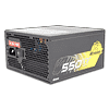
A small black, single sided PCB is used to accommodate all components of the small Venom Power PSU and most likely Andyson is the OEM of this unit. The design used is rather outdated since in the primary section we meet a plain double forward topology and in the secondary passive rectification along with a group regulated design are utilized. Of course in a budget PSU we didn't expect to see a ZVS (Zero Voltage Switching) topology in the primary but at least an indy regulated scheme in the secondary would be highly preferable. This time we fully exploited the Hakko desoldering gun and removed all three heatsinks, so you will enjoy a crystal clear view on the main PCB and its components.
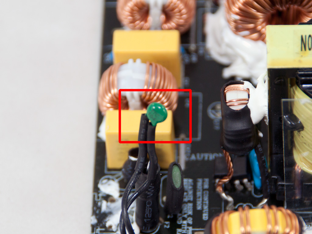
On the AC receptacle no transient filtering components are installed and the main PCB houses all of them. In total two X caps and a pair of Y ones, two small CM chokes and an MOV reside on the main PCB. Also the thermistor responsible for protection against large inrush currents is located right next to the main AC fuse and unfortunately it isn't cut off once it fulfills its duty. This is evident because there is no diode is close-by, which would indicate such a feature. As result a small amount of energy is wasted in the thermistor and more important, it doesn't cool down while the PSU is working.
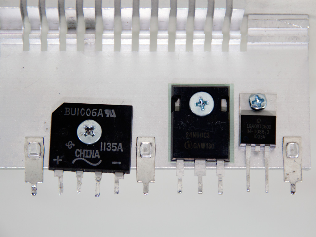

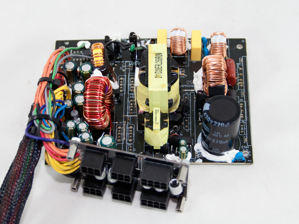
The bridge rectifier is bolted on the APFC heatsink and its model number is BUI1006A. Since the unit is compatible only with 220-240VAC input this bridge will easily handle the load but with 100-115VAC input it would be very close to its limits. The APFC uses a single SPW24N60C3 mosfet, to chop the fully rectified signal coming out from the bridge rectifier, along with the necessary boost diode, an LQA08TC600. The bulk capacitor is provided by Teapo and it is rated at 85°C. The maximum voltage it can handle is 420V and its capacitance is 270μF.
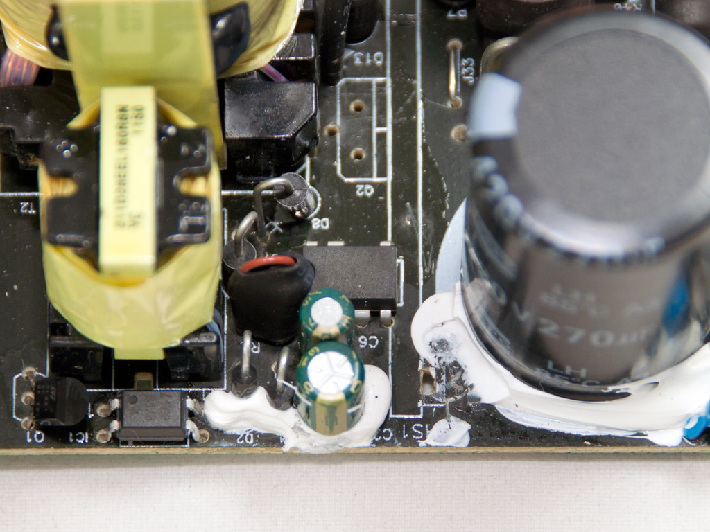

The standby PWM controller, an STR-A6069H IC and the 5VSB converter are located close to the hold up capacitor of the APFC. Two caps, a Teapo and a JunFu (not Kung Fu) filter the 5VSB rail. We don't have a problem with Teapo caps since they are probably the best, not Japan made, caps available today but JunFu caps are not widely known for their high quality, to put it gently.

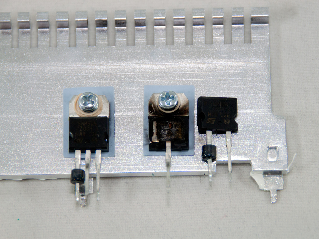
The primary heatsink is really small and houses two STP25NM50N fets. In the photos above you can see the effects of high operating temperatures in conjunction with full load output. During testing we experienced two warning shut downs, which we ignored, and on the third attempt to run the full load test at close to 50°C ambient, there was a really loud blast which cut one of the primary choppers in half. After we got a replacement unit from Akasa we were extra cautious to keep the operating temperature well below 50°C.
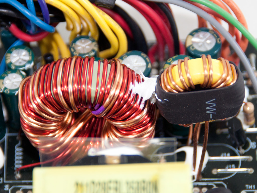
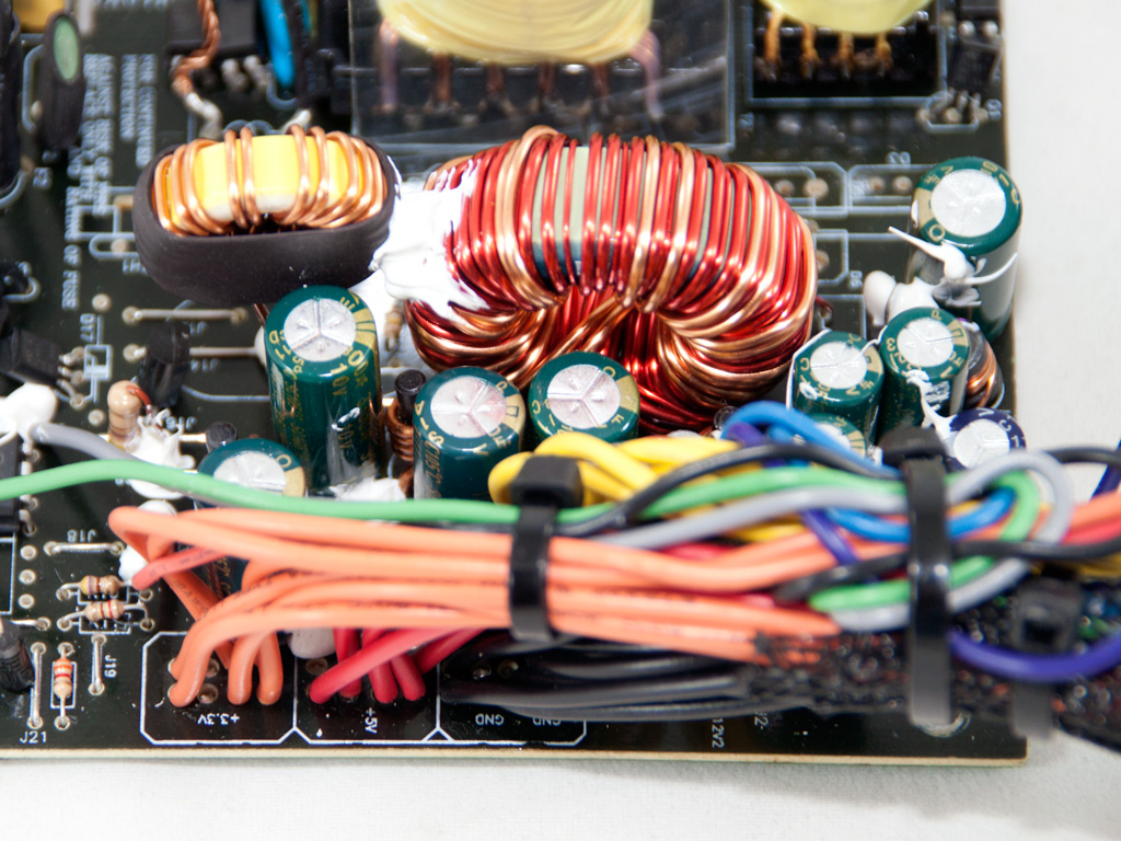
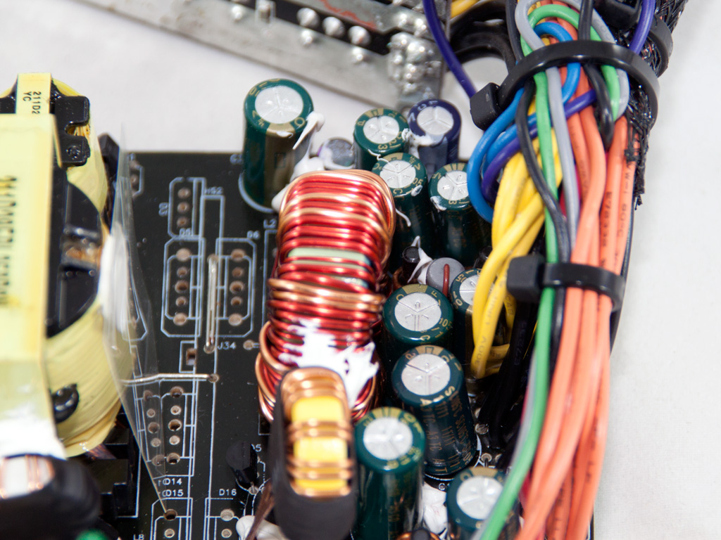
In the secondary side the presence of only two toroidal chokes means that a group regulated design is used, so the +12V and 5V rails utilize the large choke while the 3.3V rail uses the smaller one. All filtering caps in the secondary are provided by Teapo and are rated at 105°C.
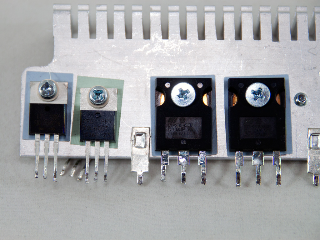
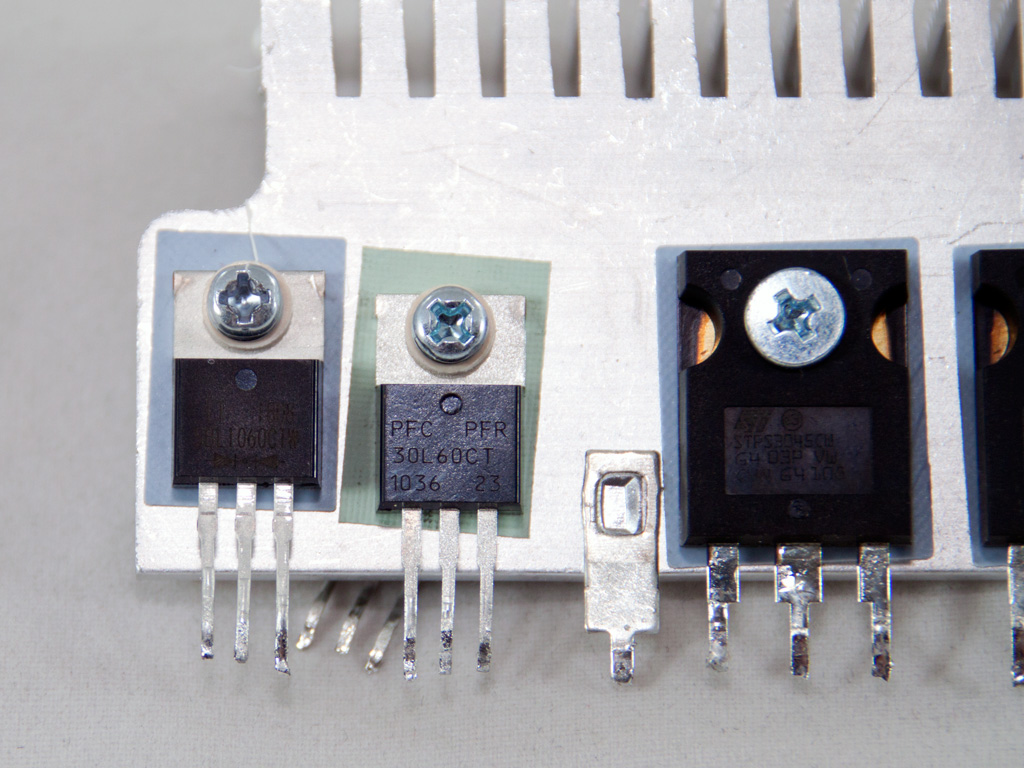
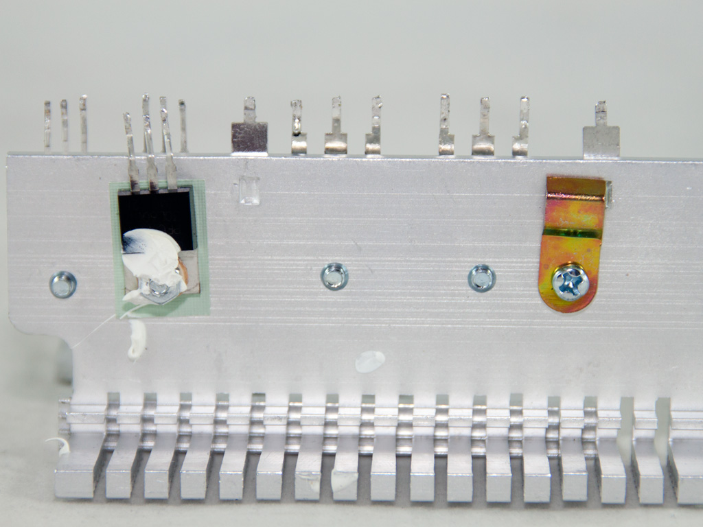
As usual the secondary heatsink houses lots of components, in this case all passive ones. On the far left we have the SBR (Schottky Barrier Diode) that handles 5VSB, an SBL1060CT. Right next to it is installed one of the two SBRs that generate +12V, a PFR30L60CT SBR. The other one is installed on the other side of the heatsink. The minor rails are generated by a pair of STPS3045CW SBRs. Each one of the aforementioned SBRs can handle up to 30A current on paper so practically they cannot handle the advertised 24A per minor rail. Finally on the same heatsink a thermistor is attached, to provide temperature information to the fan speed controller.
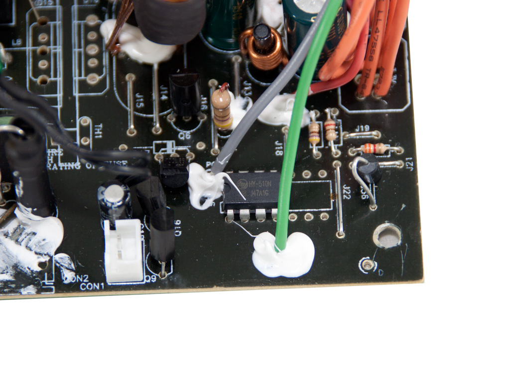
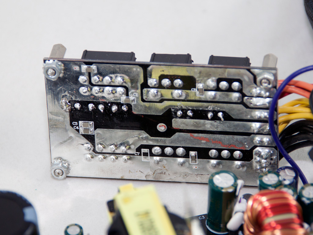
The supervisor IC is soldered on the component side of the main PCB. It is an outdated HY510N IC which doesn't support OCP contrary to Akasa's claims that this unit is equipped with this protection. Nevertheless in a single +12V rail PSU of medium-high capacity OCP is practically useless.
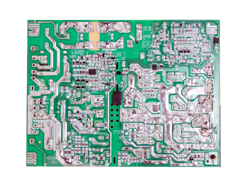

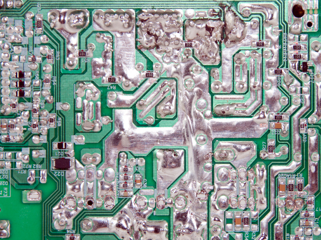
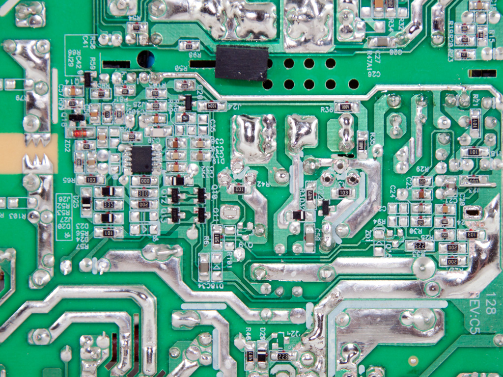
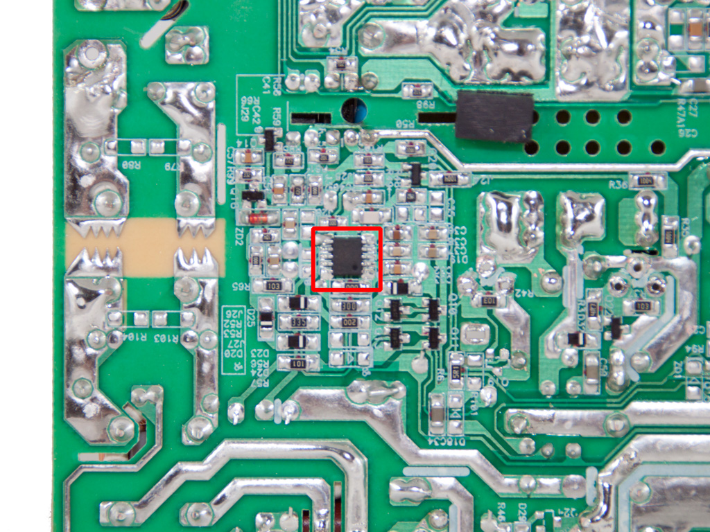
Soldering quality on the main PCB is of average quality with lots of hand made solder joints which look pretty ugly. Thankfully all component leads are short enough so they won't cause any trouble. Also on this side we found the combo PWM/PFC controller, a CM6805AG IC.
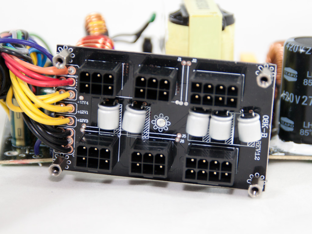

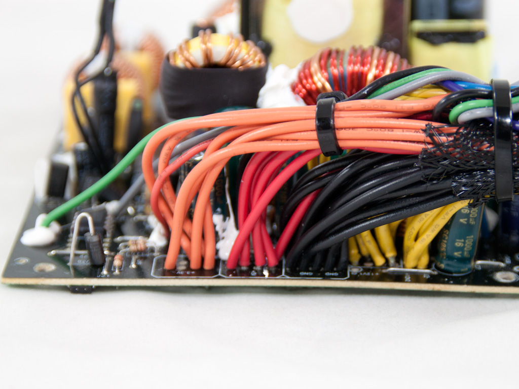
On the front of the modular PCB we find several polymer caps for extra ripple filtering. Also the same PCB is supposed to be powered by three different +12V rails but in this case all are connected together, on the main PCB.

The cooling fan wears Akasa's logo and its model number is DFS132512H (12V, 0.25A, 1700RPM, 91.16CFM, 36.28dBA). Its really made by Young Lin Tech, a Chinese company popular among PSU OEMs. Despite of its high RPMs the unit's controller keeps its speed low most of the time, so the noise output is low.
Mar 10th, 2025 18:11 EDT
change timezone
Latest GPU Drivers
New Forum Posts
- USB hard disk box capacity limits (12)
- Please I need help with the poor performance that my PC is giving me (32)
- I'm looking for a good tool to make the 3D scanning of my mini-pc using the photogrammetry and my Kinect 2. (53)
- Maxsun RX580 graphics card crashes (29)
- What is a good real price for the RTX 5090? (23)
- Microcenter GPU Stock status (31)
- Biostar RX 6700 XT OC BIOS (0)
- Msi 5090 DOA? (28)
- DLSS as antialiasing? (23)
- Cryptocoin Value and Market Trend Discussion (1646)
Popular Reviews
- Sapphire Radeon RX 9070 XT Nitro+ Review - Beating NVIDIA
- XFX Radeon RX 9070 XT Mercury OC Magnetic Air Review
- ASUS Radeon RX 9070 TUF OC Review
- MSI MAG B850 Tomahawk Max Wi-Fi Review
- NVIDIA GeForce RTX 5080 Founders Edition Review
- NVIDIA GeForce RTX 5070 Founders Edition Review
- Corsair Vengeance RGB CUDIMM DDR5-8800 48 GB CL42 Review
- AMD Ryzen 7 9800X3D Review - The Best Gaming Processor
- ASUS GeForce RTX 5070 Ti TUF OC Review
- MSI GeForce RTX 5070 Ti Gaming Trio OC+ Review
Controversial News Posts
- NVIDIA GeForce RTX 50 Cards Spotted with Missing ROPs, NVIDIA Confirms the Issue, Multiple Vendors Affected (513)
- AMD Plans Aggressive Price Competition with Radeon RX 9000 Series (277)
- AMD Radeon RX 9070 and 9070 XT Listed On Amazon - One Buyer Snags a Unit (261)
- AMD RDNA 4 and Radeon RX 9070 Series Unveiled: $549 & $599 (260)
- AMD Mentions Sub-$700 Pricing for Radeon RX 9070 GPU Series, Looks Like NV Minus $50 Again (248)
- NVIDIA Investigates GeForce RTX 50 Series "Blackwell" Black Screen and BSOD Issues (244)
- AMD Radeon RX 9070 and 9070 XT Official Performance Metrics Leaked, +42% 4K Performance Over Radeon RX 7900 GRE (195)
- AMD Radeon RX 9070-series Pricing Leaks Courtesy of MicroCenter (158)