 1
1
anidees AI6v2 Review
Assembly & Finished Looks »A Closer Look - Inside
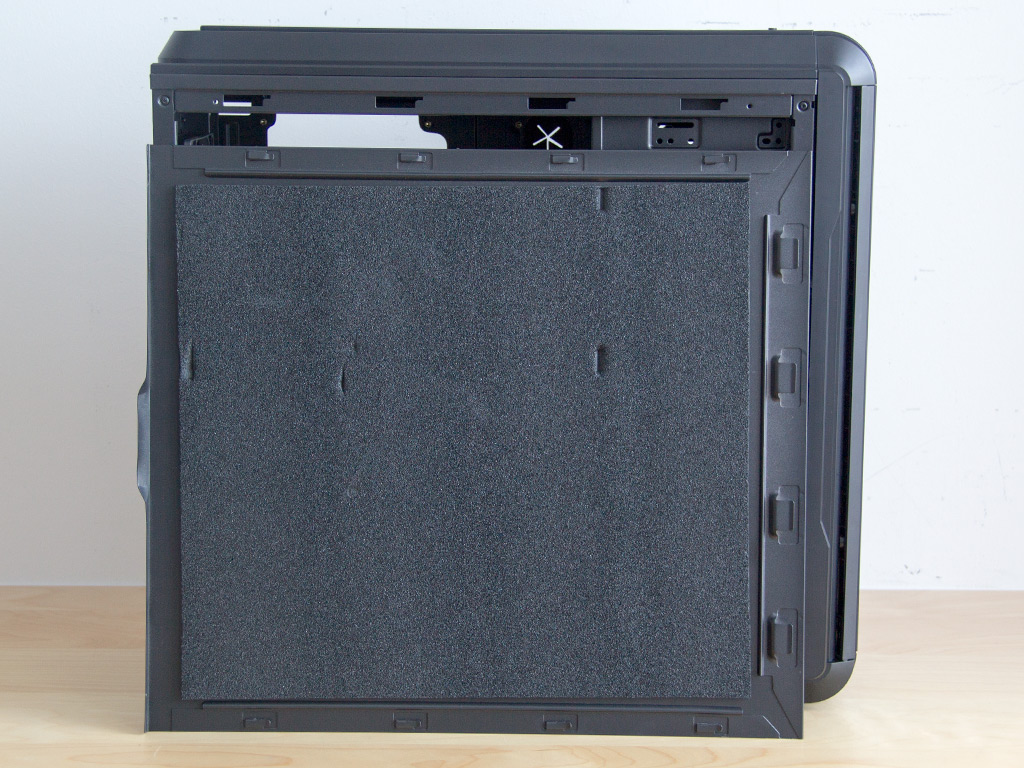
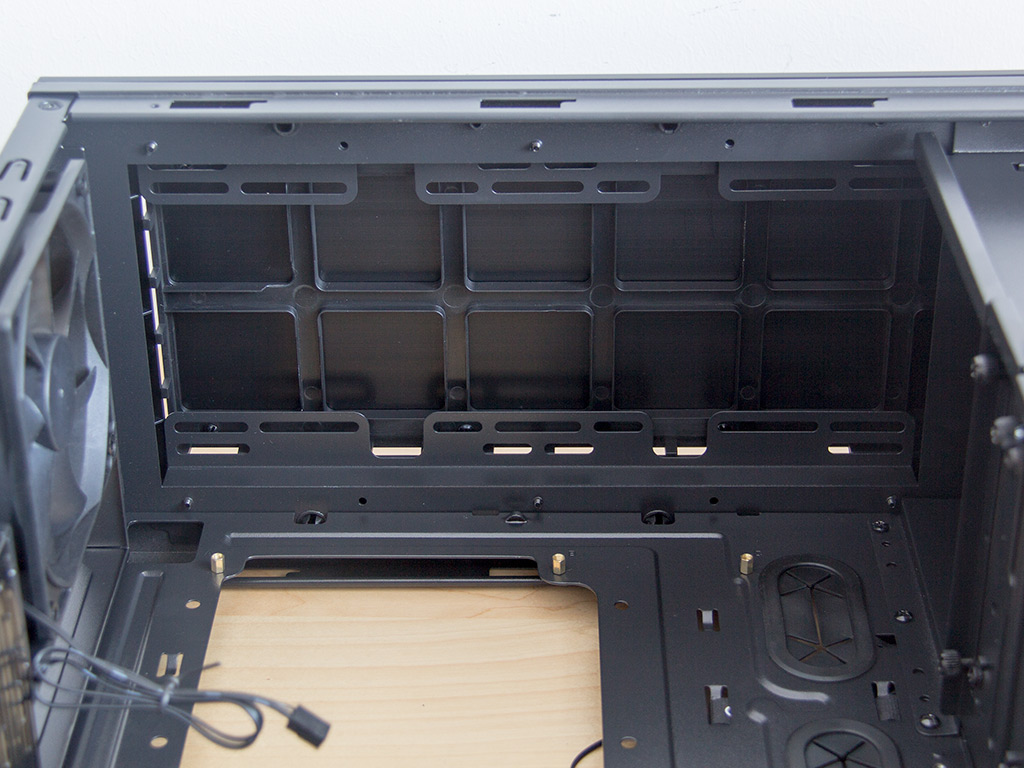
To access the interior of the chassis, simply remove the two thumbscrews holding each side panel in place. The interior layout is quite traditional, but the paint job is very fine and of high quality. Multiple openings in the motherboard tray should allow for excellent cable routing, which will result in a clean interior, and a large hole in the motherboard tray makes accessing CPU cooler backplates without having to remove the entire board possible.
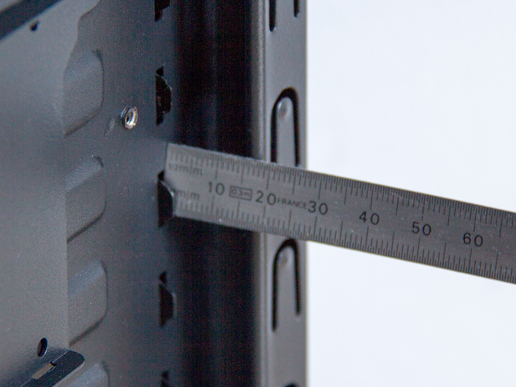
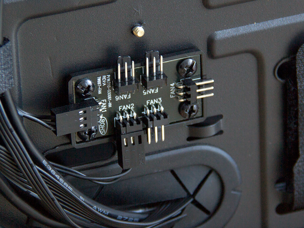
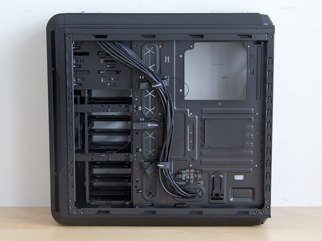
There is only around 18 mm of space behind the motherboard tray. While enough, things will be rather tight for good cable management. The fan controller at the top leads to a little splitter PCB you can easily attach all your units to.
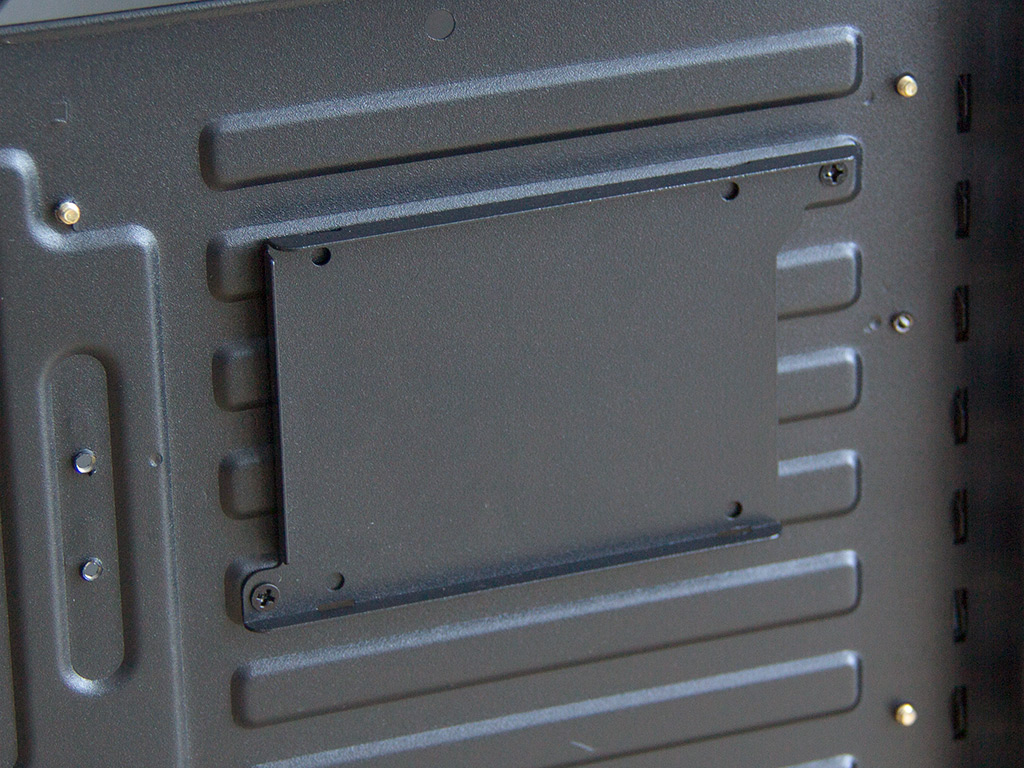

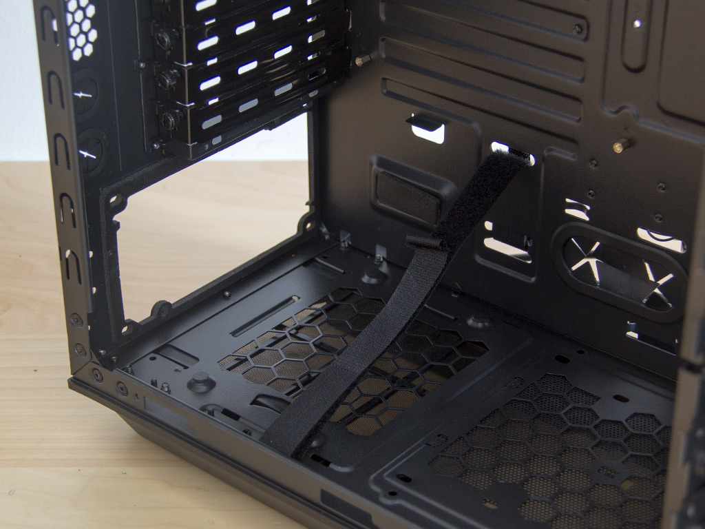
Another addition is the SSD tray behind the motherboard tray. It is rather simple, but should do the job. Experience has shown that these flat trays tend to make plugging some SATA power cables into them rather difficult if the plugs are angled the wrong way. Last, but not least, you will find some very useful Velcro strips with which you can hold cables in place. These will prove useful when routing cables down this side of the tray.

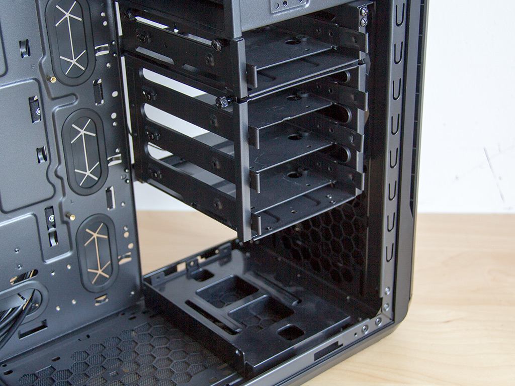
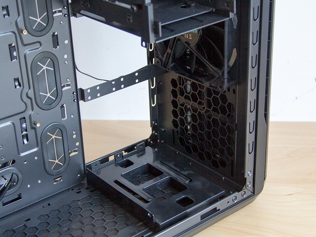
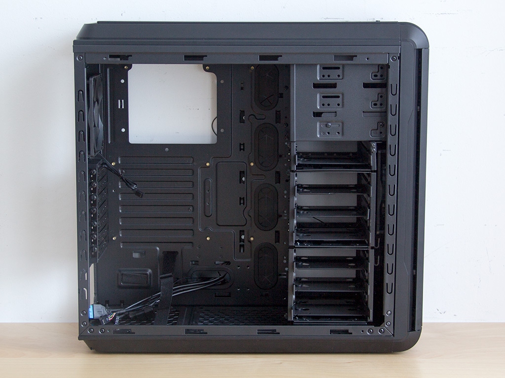
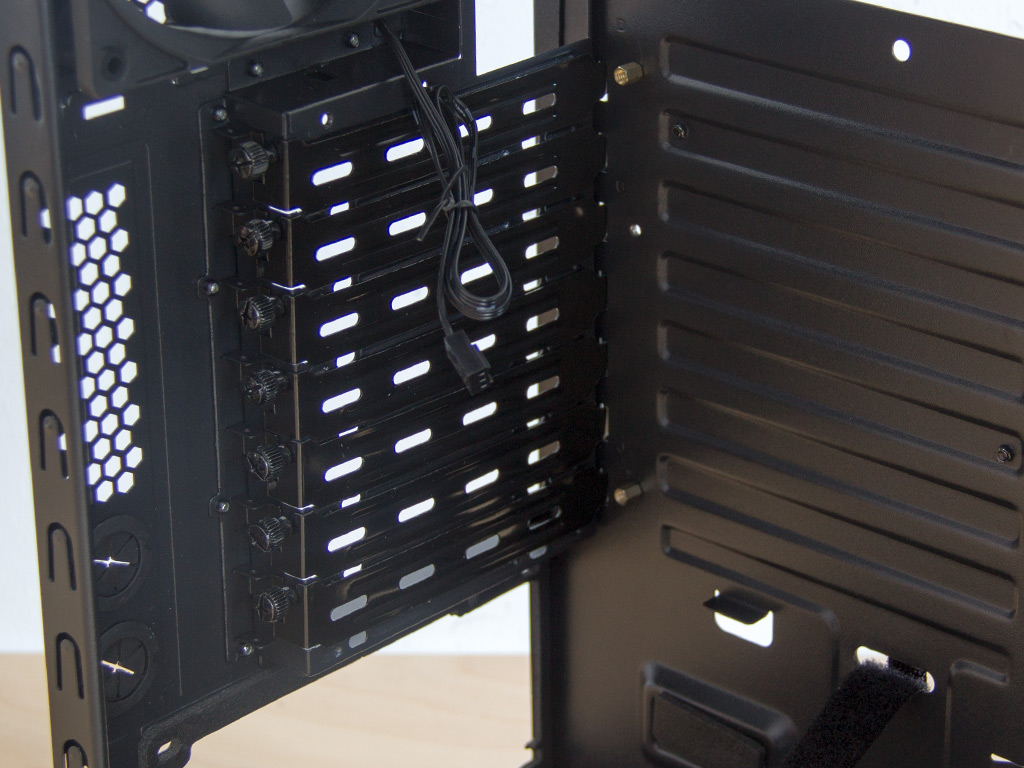
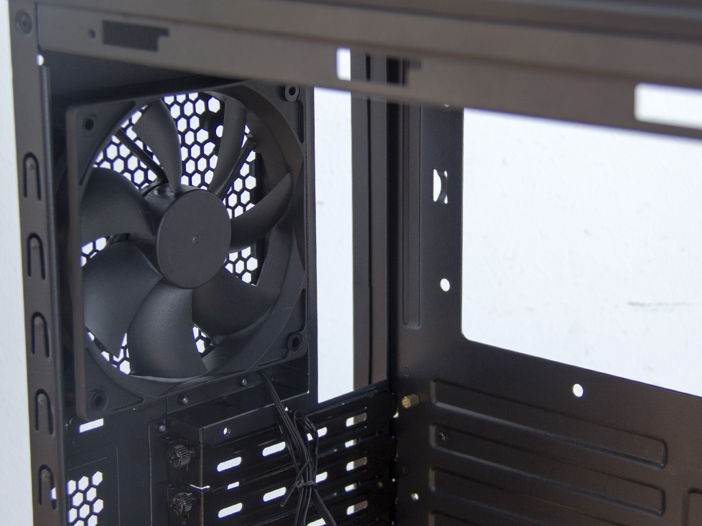
The AI6v2 can hold up to seven hard drives. These are divided into three cages, with the ability to remove the bottom two. Doing so will leave you with one bay and enough room four incredibly long graphics cards and a functional system. anidees improved this area by adding more securing points, which ensures nothing is loose when you remove one of these cages, for example. You may install up to two fans into the chassis front, and anidees includes a 140 mm unit here out of the box.
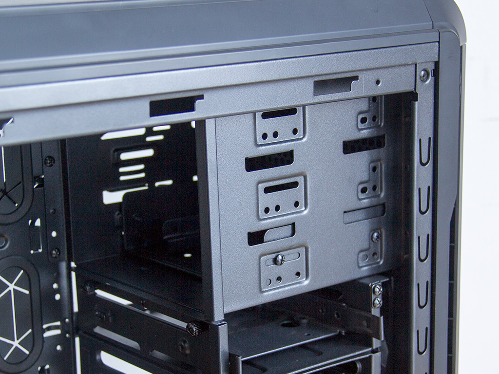
You will find three 5.25" drive bays in the top. One of these is filled with the aforementioned 3.5" adapter tray. There are no plastic locks as you will use proper thumbscrews to hold any drives in place. While a refreshing approach, it is also one befitting the chassis's price tag.
In the rear, you have the PSU bay on the bottom. A Velcro strip and screws are used to secure a PSU in place. The Velcro strip is a pretty cool little touch and should suffice for those never planning to move their system around, allowing for the exclusion of screws. Above that are the motherboard expansion slots, each protected by a separate cover and held in place by thumbscrews. A single 120 mm exhaust fan with a 3-pin connector has been put into the top.
You may install two 120 mm or 140 mm fans into the ceiling. Thanks to perfect spacing, placing a 240 mm or 280 mm radiator here should also be possible. This area was redesigned completely, so you can expect it to be much more flexible, which is due to the elongated mounting holes and straight edges.
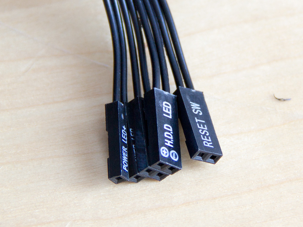
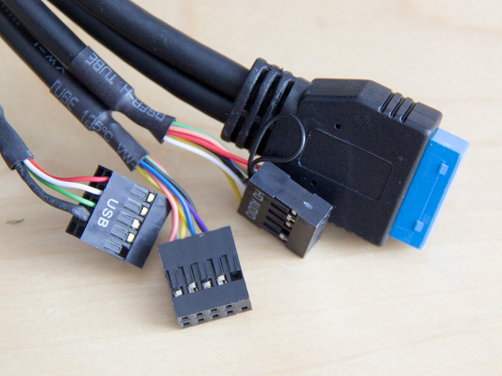
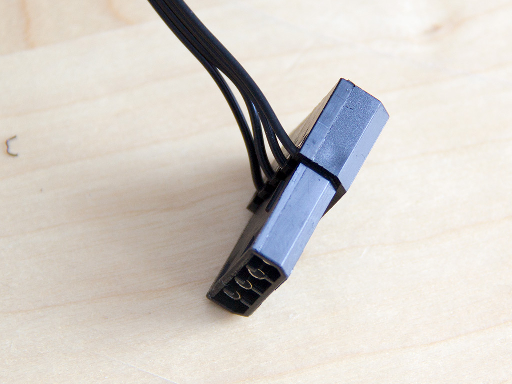
The cables within the chassis are nothing out of the ordinary. anidees updated the color of the USB 3.0 cable for the v2 to make it match the interior. There is also a Molex connector for the fan controller.
Apr 7th, 2025 12:46 EDT
change timezone
Latest GPU Drivers
New Forum Posts
- Folding Pie and Milestones!! (9462)
- AMD RX 9070 XT & RX 9070 non-XT thread (OC, undervolt, benchmarks, ...) (83)
- How I made an Ultimate Cooling Guide (28)
- gpu heirarchy/performance/benchmarks- whos lying? (63)
- Cryptocoin Value and Market Trend Discussion (1648)
- did i break housing of my ssd or something? (2)
- Throttlestop/Undervolting broken by MacOS VoltageShift (possibly) (5)
- Possible to stream your nintendo switch to discord ? (6)
- 9070XT or 7900XT or 7900XTX (66)
- What's your latest tech purchase? (23492)
Popular Reviews
- ASUS Prime X870-P Wi-Fi Review
- UPERFECT UStation Delta Max Review - Two Screens In One
- PowerColor Radeon RX 9070 Hellhound Review
- Upcoming Hardware Launches 2025 (Updated Apr 2025)
- Corsair RM750x Shift 750 W Review
- Sapphire Radeon RX 9070 XT Pulse Review
- Sapphire Radeon RX 9070 XT Nitro+ Review - Beating NVIDIA
- DDR5 CUDIMM Explained & Benched - The New Memory Standard
- AMD Ryzen 7 9800X3D Review - The Best Gaming Processor
- AMD Ryzen 9 9950X3D Review - Great for Gaming and Productivity
Controversial News Posts
- NVIDIA GeForce RTX 5060 Ti 16 GB SKU Likely Launching at $499, According to Supply Chain Leak (152)
- MSI Doesn't Plan Radeon RX 9000 Series GPUs, Skips AMD RDNA 4 Generation Entirely (146)
- Microsoft Introduces Copilot for Gaming (124)
- AMD Radeon RX 9070 XT Reportedly Outperforms RTX 5080 Through Undervolting (119)
- NVIDIA Reportedly Prepares GeForce RTX 5060 and RTX 5060 Ti Unveil Tomorrow (115)
- Over 200,000 Sold Radeon RX 9070 and RX 9070 XT GPUs? AMD Says No Number was Given (100)
- NVIDIA GeForce RTX 5050, RTX 5060, and RTX 5060 Ti Specifications Leak (97)
- Nintendo Switch 2 Launches June 5 at $449.99 with New Hardware and Games (92)