 28
28
Antec Signature Titanium 1000 W Review - Return of the Legend
Protection Features Evaluation, DC Power Sequencing & EMC Pre-Compliance Testing »Advanced Transient Response Tests
In these tests, we monitor the response of the PSU in two different scenarios. First, a transient load (10 A at +12V, 5 A at +5V, 5 A at +3.3V, and 0.5 A at 5VSB) is applied to the PSU for 200 ms while the latter is working at 20% load. In the second scenario, the PSU, while working at 50% load, is hit by the same transient load. We measure the voltage drops the transient load causes with our oscilloscope in both tests. Voltages should remain within the regulation limits defined by the ATX specification.Real-world usage always has a PSU work with loads that change depending on whether the CPU or graphics cards are busy, which makes whether the PSU can keep its rails within the ranges defined by the ATX specification important. The smaller the deviations, the steadier the system will be, which results in less stress being applied to its components.
We should note that the ATX specification requires for capacitive loading during the transient tests, but in our methodology, we chose to apply the worst-case scenario with no extra capacitance on the rails. Although the ATX specifications asks for this capacitance, your system—the mainboard and its other parts—may not provide it, which we have to keep in mind as well.
| Advanced Transient Response 20% - 50 Hz | ||||
|---|---|---|---|---|
| Voltage | Before | After | Change | Pass/Fail |
| 12 V | 12.302V | 12.158V | 1.17% | Pass |
| 5 V | 5.096V | 5.011V | 1.67% | Pass |
| 3.3 V | 3.365V | 3.229V | 4.04% | Pass |
| 5VSB | 4.956V | 4.912V | 0.89% | Pass |
| Advanced Transient Response 50% - 50 Hz | ||||
|---|---|---|---|---|
| Voltage | Before | After | Change | Pass/Fail |
| 12 V | 12.290V | 12.193V | 0.79% | Pass |
| 5 V | 5.090V | 5.002V | 1.73% | Pass |
| 3.3 V | 3.359V | 3.215V | 4.29% | Pass |
| 5VSB | 4.917V | 4.880V | 0.75% | Pass |
With 20% load, the transient response at +12 V is slightly over 1%, but the voltage is still much higher than 12 V. With 50% load, the deviation is below 1%, which is as expected for a modern high-capacity platform. My only concern here is the deviation above 4% in both 3.3 V tests, but the voltage is still above 3.2 V in both cases.
Below are the oscilloscope screenshots we took during Advanced Transient Response testing.
Transient Response at 20% Load

Transient Response at 50% Load
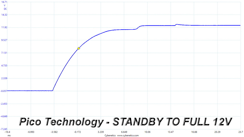
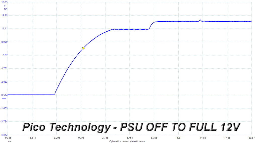
Turn-On Transient Tests
We measure the response of the PSU in more straightforward scenarios of transient load—during the power-on phase of the PSU—in the next set of tests. In the first test, we turn the PSU off, dial the maximum current the 5VSB can output, and then switch on the PSU. In the second test, we dial the maximum load +12V can handle and start the PSU while the PSU is in standby mode. In the last test, while the PSU is completely switched off (we cut off power or switch the PSU off by flipping its on/off switch), we dial the maximum load the +12V rail can handle before switching the PSU on from the loader and restoring power. The ATX specification states that recorded spikes on all rails should not exceed 10% of their nominal values (e.g., +10% for +12V is 13.2 V and 5.5 V for +5V).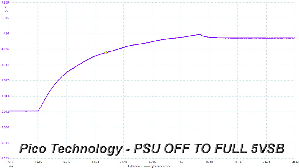
Power Supply Timing Tests
| Power Supply Timing | ||
|---|---|---|
| Parameter | Description | Recommended Value - Includes Support for Alternative Sleep Mode |
| T0 | AC power on time | < 2s |
| T1 | Power-on time | < 150 ms |
| T2 | Rise time | 0.2 - 20 ms |
| T3 | PWR_OK delay | 100 - 150 ms |
| T4 | PWR_OK rise time | < 10 ms |
| T5 | AC loss to PWR_OK hold-up time | > 16 ms |
| T6 | PWR_OK inactive to DC loss delay | > 1 ms |
The table above lists all required power supply timing values.
| T1 (Power-on time) & T3 (PWR_OK delay) | ||
|---|---|---|
| Load | T1 | T3 |
| 20% | 132 ms | 322 ms |
| 100% | 144 ms | 324 ms |
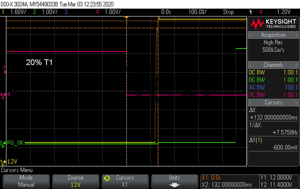
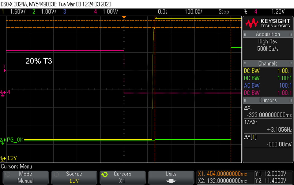
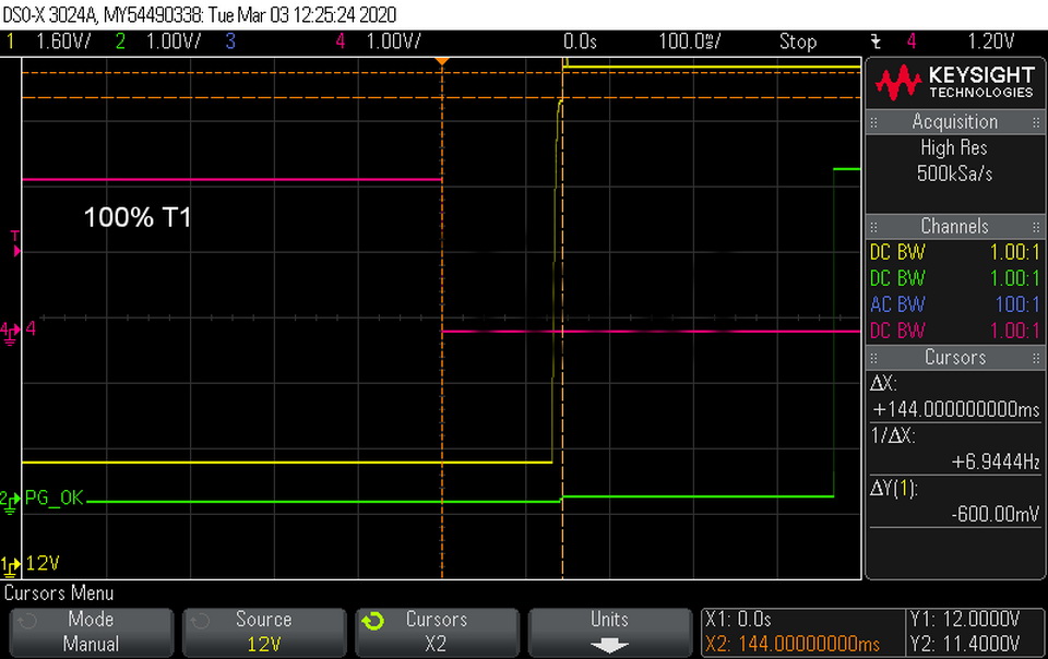
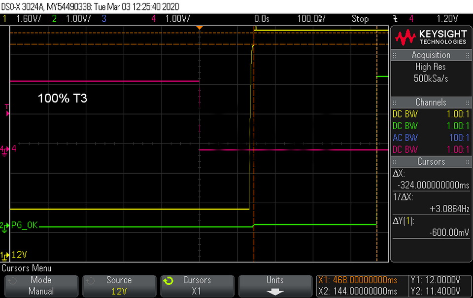
Both the Power-on (T1) and Power_OK delay (T3) periods are quite long. I would like to see values below 100 ms for T1 and within 100–150 ms for T3.
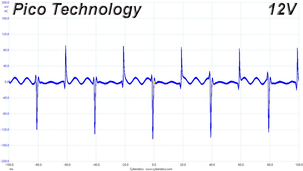
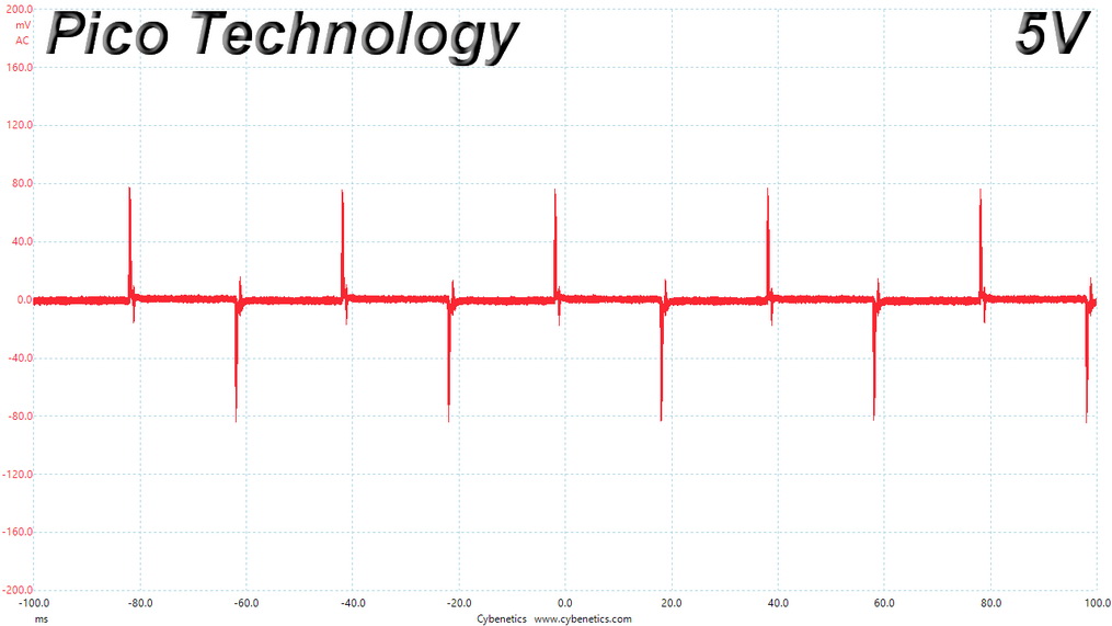
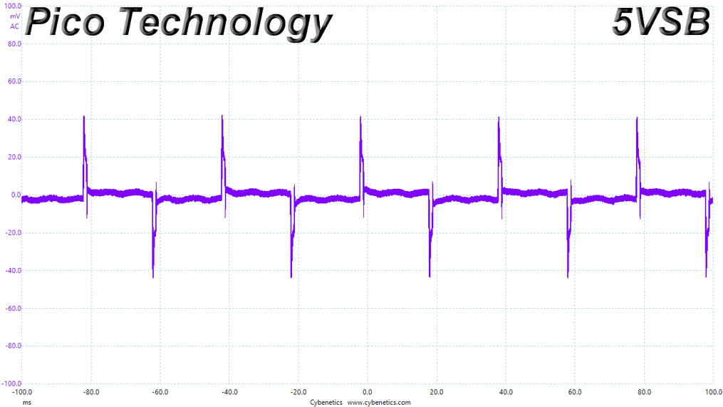
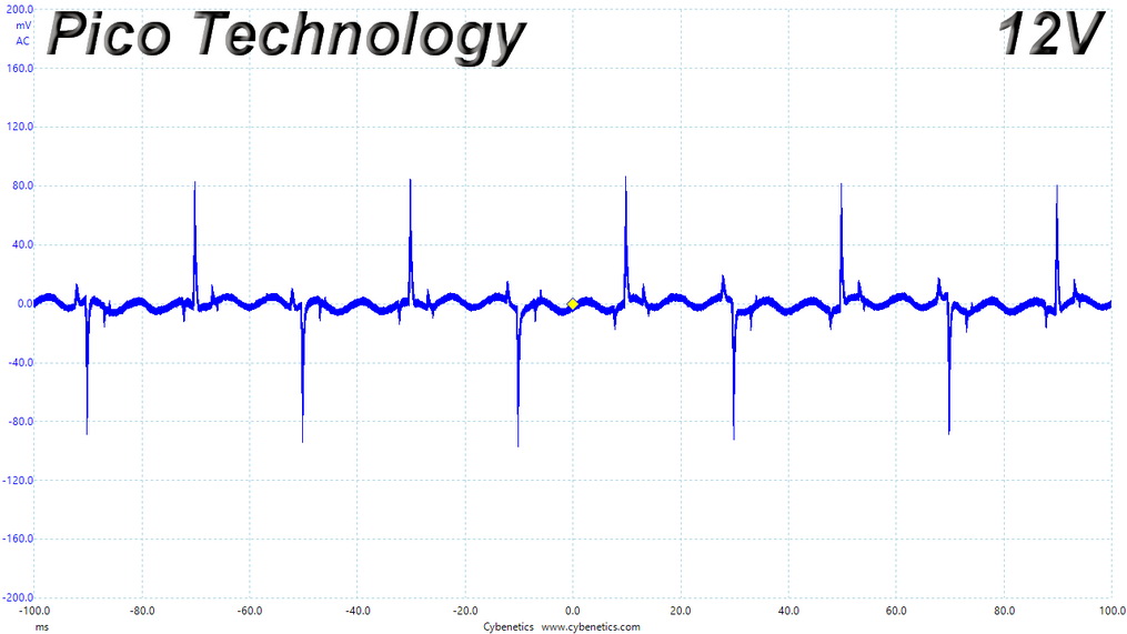
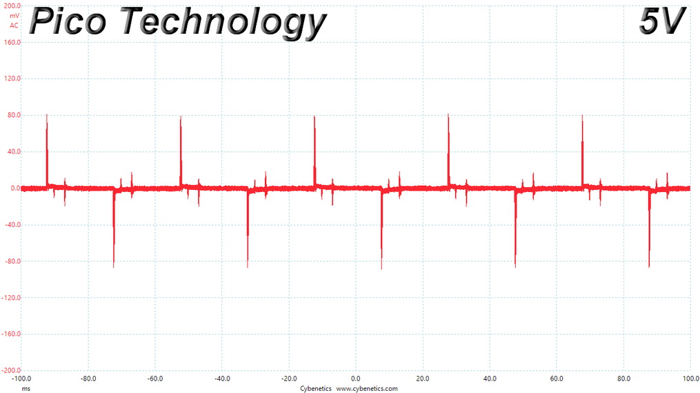
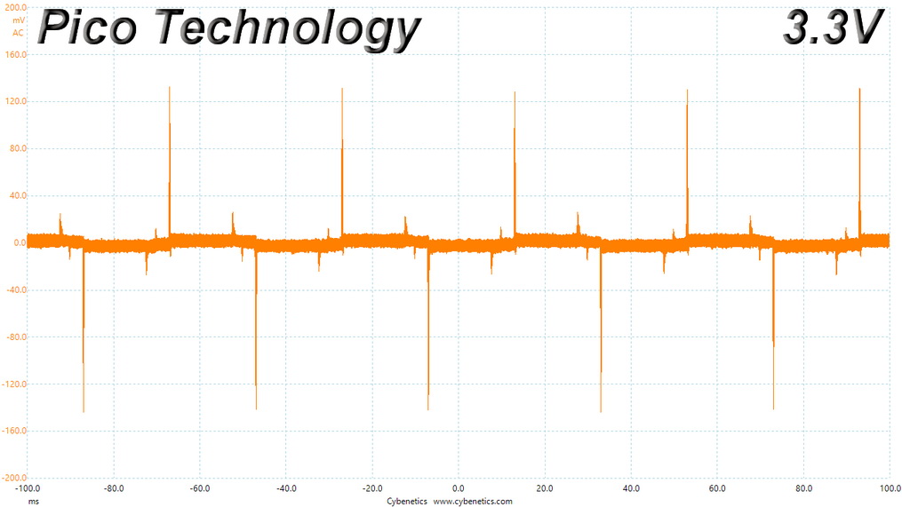
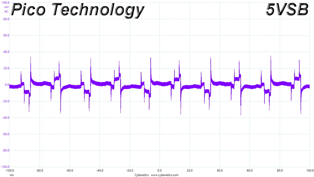
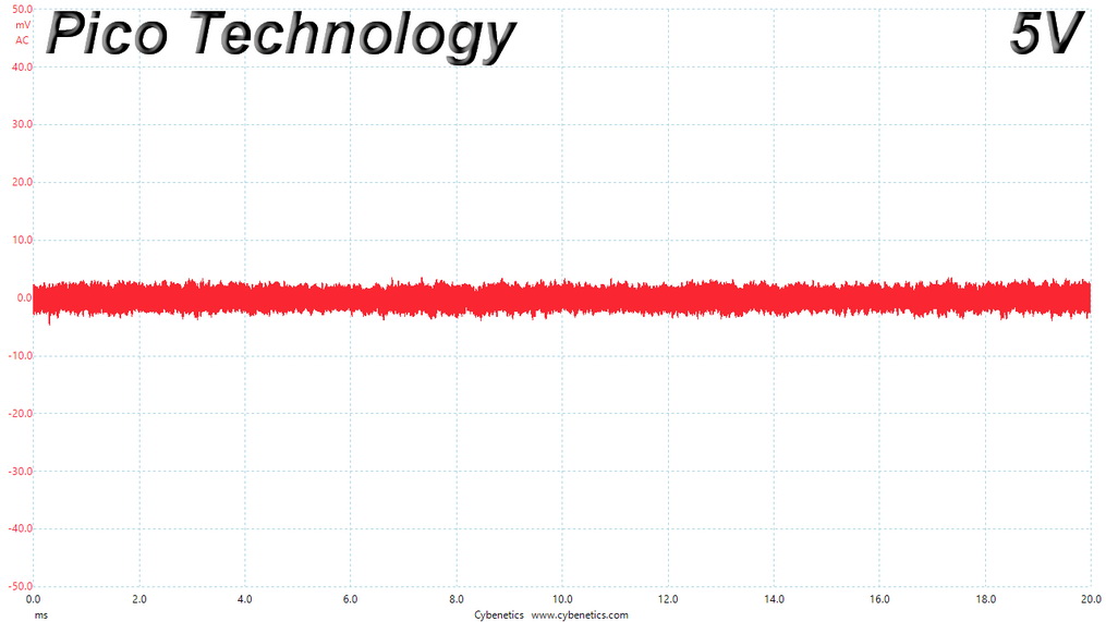
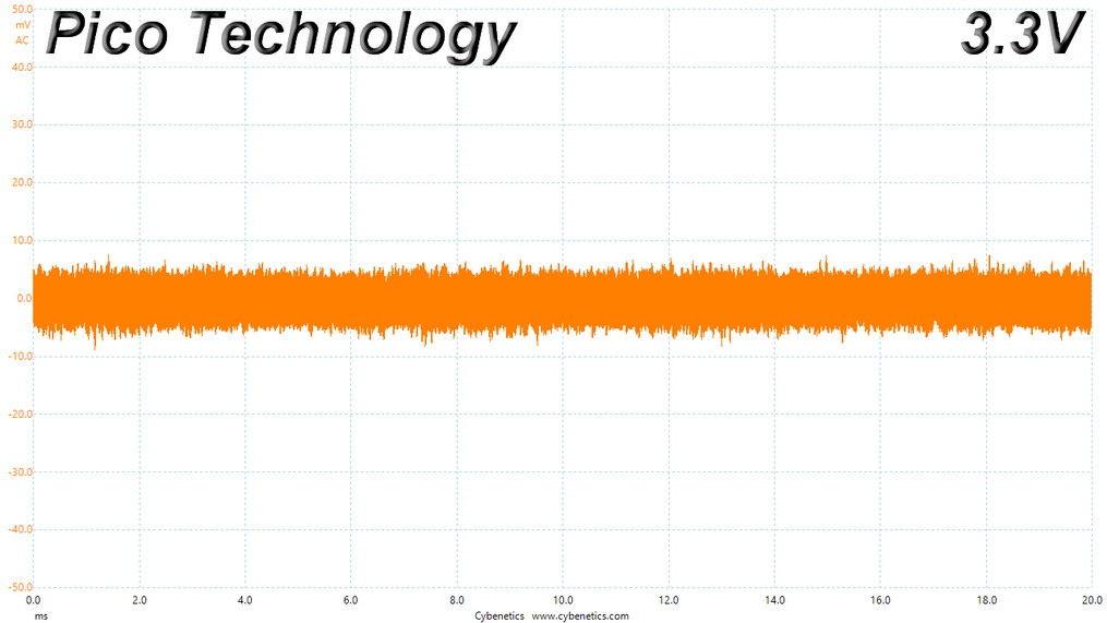
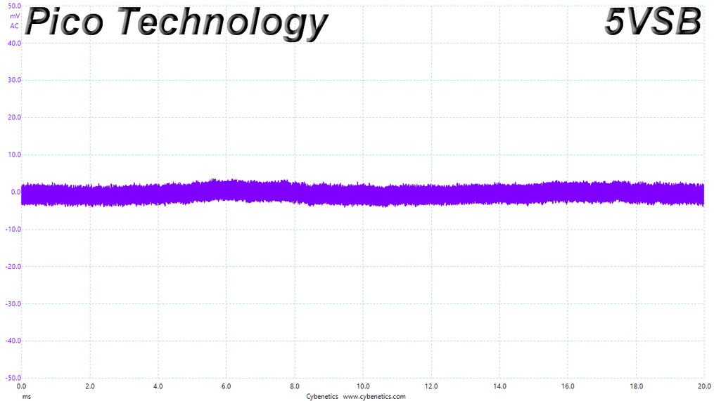
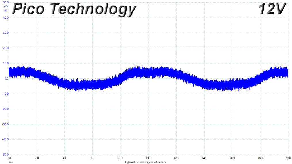
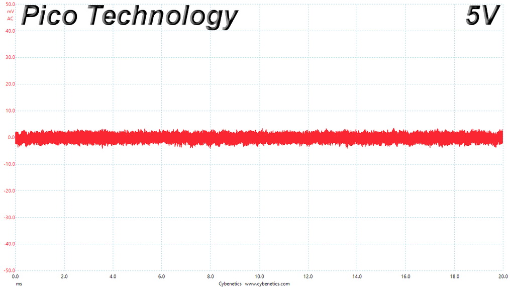
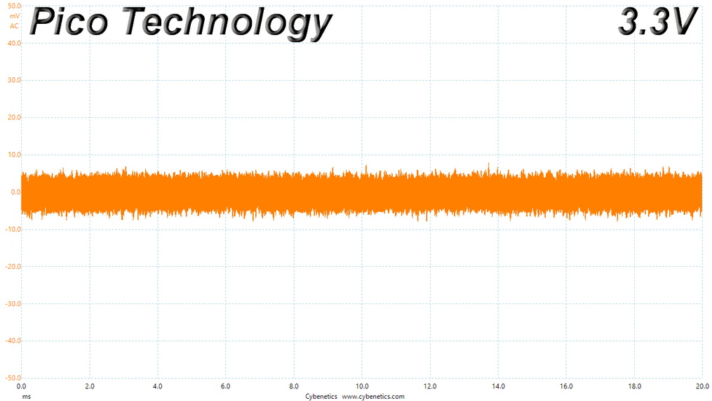
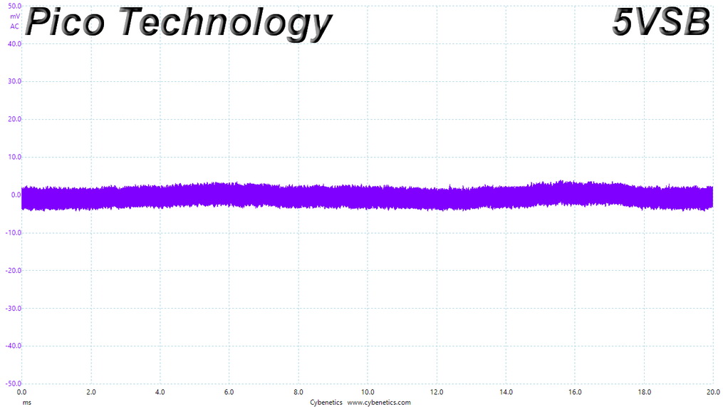
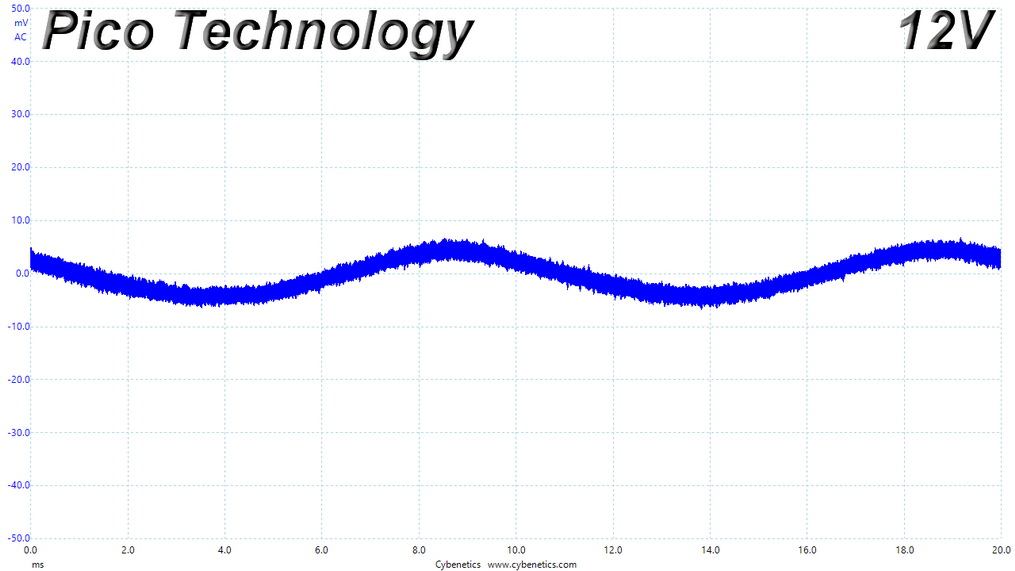
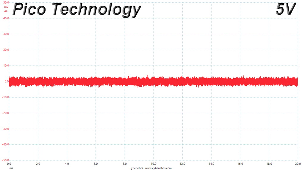
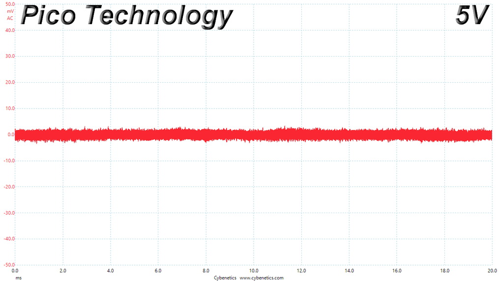
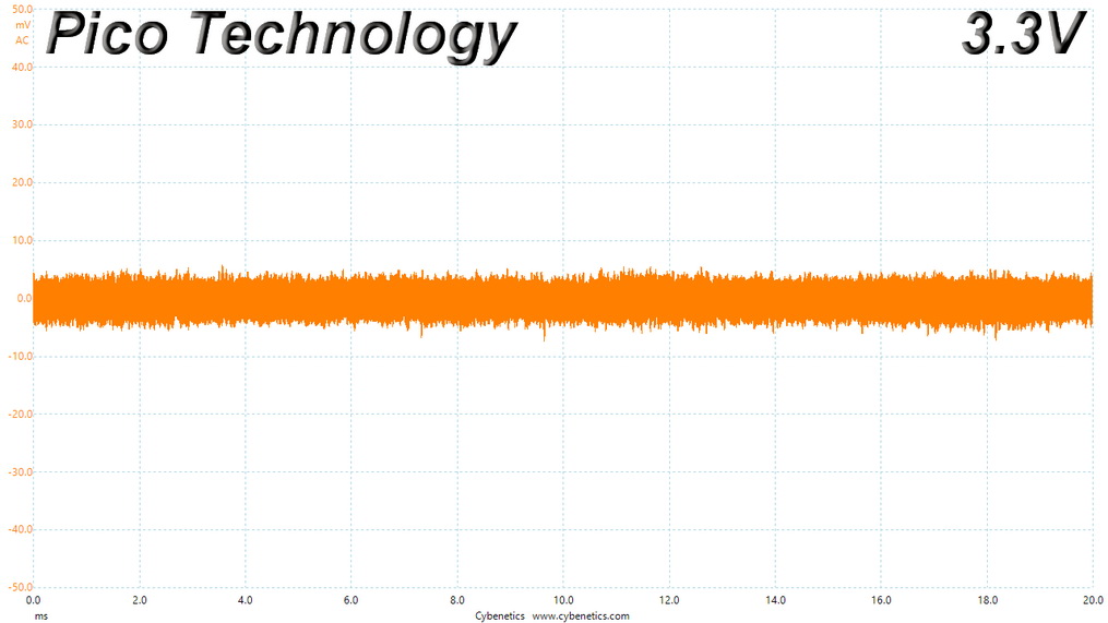
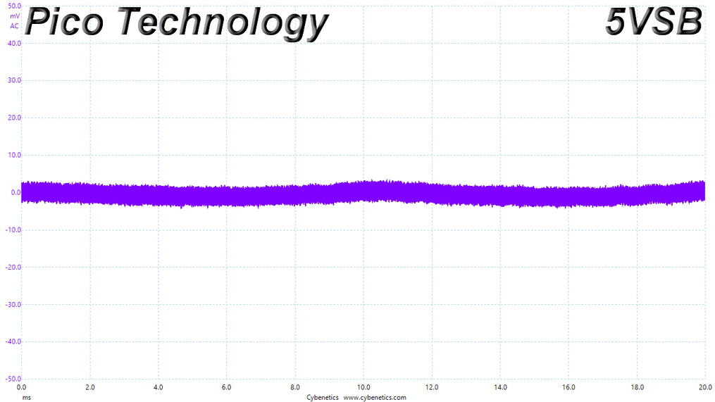
Ripple Measurements
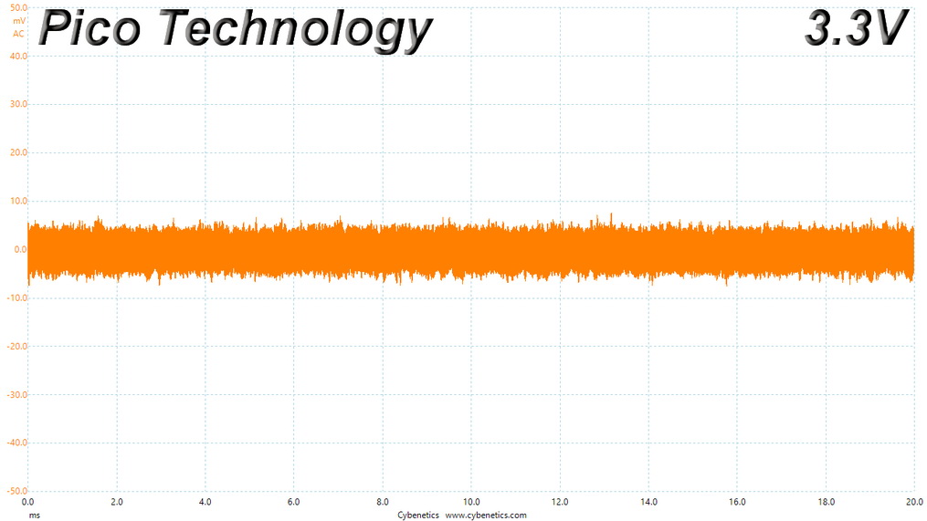
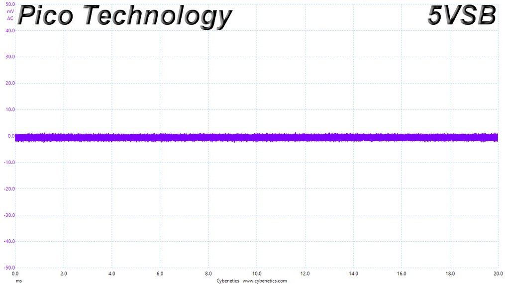
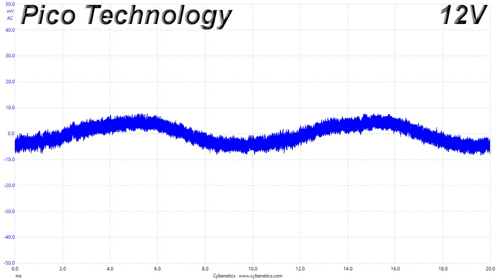
Ripple represents the AC fluctuations (periodic) and noise (random) found in the DC rails of PSUs. Ripple significantly decreases the life span of capacitors because it increases their temperature; a 10 °C increase can cut into a capacitor's life span by up to 50 percent. Ripple also plays an important role in overall system stability, especially when it is overclocked. The ripple limits according to the ATX specification are 120 mV (+12V) and 50 mV (+5V, +3.3V, and 5VSB).| Ripple Measurements - Antec Signature 1000 Titanium | |||||
|---|---|---|---|---|---|
| Test | 12 V | 5 V | 3.3 V | 5VSB | Pass/Fail |
| 10% Load | 9.3 mV | 6.4 mV | 13.3 mV | 3.5 mV | Pass |
| 20% Load | 11.5 mV | 6.9 mV | 12.9 mV | 4.2 mV | Pass |
| 30% Load | 10.6 mV | 6.8 mV | 15.0 mV | 4.2 mV | Pass |
| 40% Load | 7.9 mV | 8.0 mV | 14.7 mV | 4.7 mV | Pass |
| 50% Load | 8.1 mV | 8.0 mV | 15.2 mV | 5.6 mV | Pass |
| 60% Load | 9.1 mV | 7.7 mV | 15.4 mV | 6.1 mV | Pass |
| 70% Load | 9.4 mV | 7.4 mV | 15.5 mV | 6.4 mV | Pass |
| 80% Load | 10.4 mV | 7.8 mV | 16.0 mV | 6.5 mV | Pass |
| 90% Load | 11.0 mV | 8.1 mV | 16.6 mV | 7.0 mV | Pass |
| 100% Load | 17.1 mV | 9.0 mV | 17.5 mV | 8.4 mV | Pass |
| 110% Load | 18.5 mV | 8.9 mV | 17.6 mV | 9.1 mV | Pass |
| Crossload 1 | 13.9 mV | 8.9 mV | 16.3 mV | 4.2 mV | Pass |
| Crossload 2 | 17.7 mV | 7.7 mV | 13.9 mV | 8.3 mV | Pass |
Ripple suppression is great on all rails even though there are no in-cable caps.
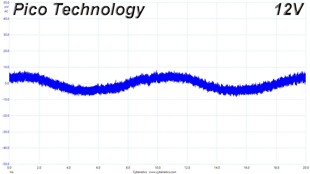
Ripple at Full Load
Ripple at 110% Load
Ripple at Crossload 1
Ripple at Crossload 2
Feb 23rd, 2025 07:12 EST
change timezone
Latest GPU Drivers
New Forum Posts
- Advice needed for buying a new PSU (8)
- Cooler for r7 5700X3D [Stock] (5)
- Keep a 4080s or take a 5070ti? (33)
- Sapphire NITRO+ RX 5700 XT BE original BIOS request (3)
- RTX 5070 Ti Benelux pricing. It hurts (18)
- What are you playing? (22978)
- EFI partition too small, can't update Windows 11 on laptop (2)
- It's happening again, melting 12v high pwr connectors (886)
- 5800X3D CO and RAM - Thoughts? (15)
- The Vega VII Owners Club (109)
Popular Reviews
- MSI GeForce RTX 5070 Ti Ventus 3X OC Review
- ASUS GeForce RTX 5070 Ti TUF OC Review
- Ducky One X Inductive Keyboard Review
- Galax GeForce RTX 5070 Ti 1-Click OC White Review
- MSI GeForce RTX 5070 Ti Vanguard SOC Review
- darkFlash DY470 Review
- Gigabyte GeForce RTX 5090 Gaming OC Review
- MSI GeForce RTX 5070 Ti Gaming Trio OC+ Review
- Palit GeForce RTX 5070 Ti GameRock OC Review
- Fantech Aria II Pro Review
Controversial News Posts
- NVIDIA GeForce RTX 5090 Spotted with Missing ROPs, NVIDIA Confirms the Issue, Multiple Vendors Affected, RTX 5070 Ti, Too (425)
- AMD Radeon 9070 XT Rumored to Outpace RTX 5070 Ti by Almost 15% (302)
- AMD Plans Aggressive Price Competition with Radeon RX 9000 Series (271)
- AMD Radeon RX 9070 and 9070 XT Listed On Amazon - One Buyer Snags a Unit (247)
- Edward Snowden Lashes Out at NVIDIA Over GeForce RTX 50 Pricing And Value (241)
- AMD Denies Radeon RX 9070 XT $899 USD Starting Price Point Rumors (239)
- New Leak Reveals NVIDIA RTX 5080 Is Slower Than RTX 4090 (215)
- NVIDIA Investigates GeForce RTX 50 Series "Blackwell" Black Screen and BSOD Issues (185)