 12
12
Cooler Master V550S with 3D Circuit Design Review
Ripple Measurements »Advanced Transient Response Tests
These tests monitor the response of the PSU in two different scenarios. First, a transient load (10 A at +12V, 5 A at 5V, 5 A at 3.3V, and 0.5 A at 5VSB) is applied to the PSU for 200 ms while the latter is working at 20% load. In the second scenario, the PSU, while working at 50% load, is hit by the same transient load. In both tests, we measure the voltage drops the transient load causes using our oscilloscope. The voltages should remain within the regulation limits defined by the ATX specification. We must stress here that the above tests are crucial because they simulate transient loads a PSU is very likely to handle (e.g., booting a RAID array, an instant 100% load of CPU/VGAs, etc.). We call these tests "Advanced Transient Response Tests", and they are designed to be very tough to master, especially for PSUs with capacities below 500 W.| Advanced Transient Response 20% | ||||
|---|---|---|---|---|
| Voltage | Before | After | Change | Pass/Fail |
| 12 V | 12.279V | 12.133V | 1.19% | Pass |
| 5 V | 5.007V | 4.923V | 1.68% | Pass |
| 3.3 V | 3.320V | 3.214V | 3.19% | Pass |
| 5VSB | 4.981V | 4.905V | 1.53% | Pass |
| Advanced Transient Response 50% | ||||
|---|---|---|---|---|
| Voltage | Before | After | Change | Pass/Fail |
| 12 V | 12.249V | 12.133V | 0.95% | Pass |
| 5 V | 4.987V | 4.902V | 1.70% | Pass |
| 3.3 V | 3.299V | 3.193V | 3.21% | Pass |
| 5VSB | 4.951V | 4.890V | 1.23% | Pass |
The V550S performed well, though its relatively small capacity is a significant handicap in these tests. It only registered small deviations on all rails, with +12V, the most important rail of all, being close to 1% on both tests. We were left pretty satisfied by its Advanced Transient Response performance.
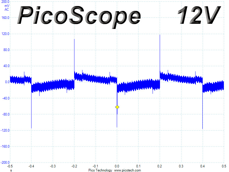
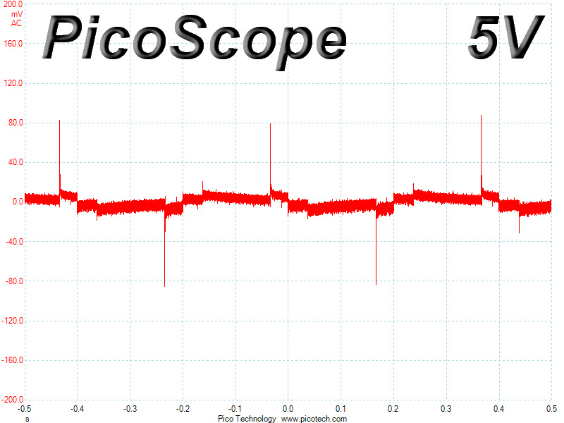
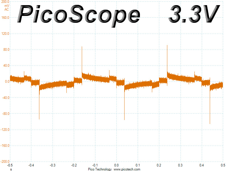
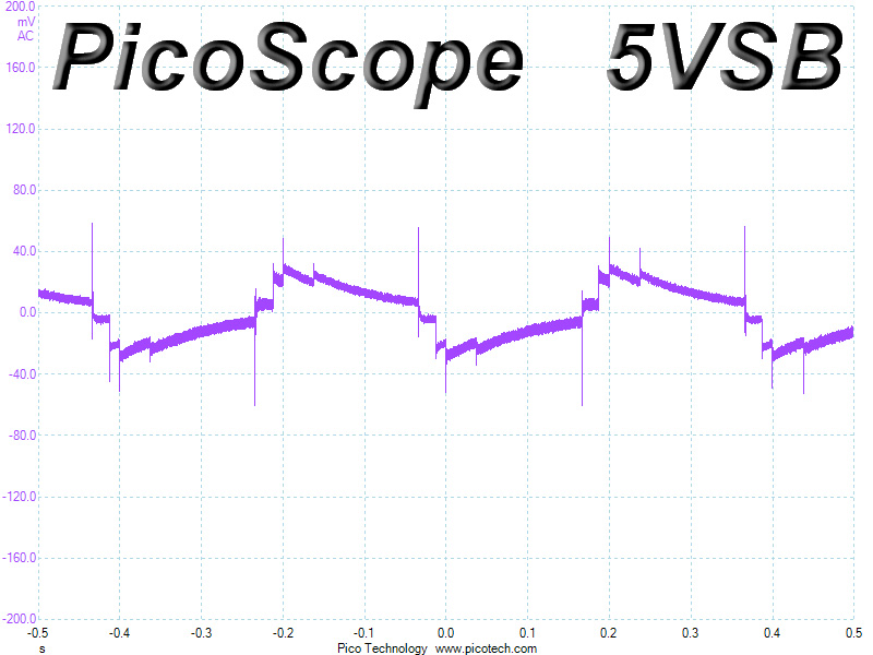
Below are the oscilloscope screenshots we took during Advanced Transient Response testing.
Transient Response at 20% Load
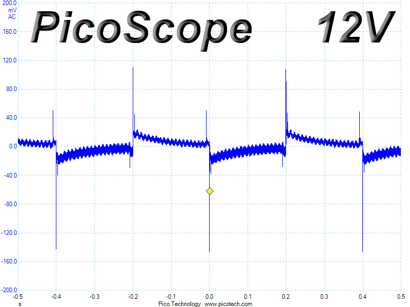
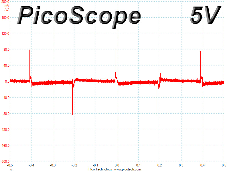
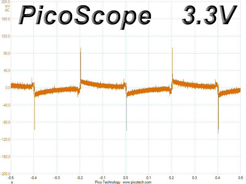
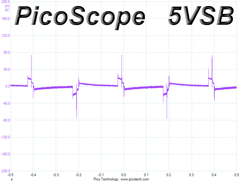
Transient Response at 50% Load
Turn-On Transient Tests
We measure the response of the PSU in simpler scenarios of transient loads—during the power-on phase of the PSU—in the next set of tests. In the first test, we turn the PSU off, dial the maximum current the 5VSB can output, and then switch on the PSU. In the second test, we dial the maximum load +12V can handle and start the PSU while the PSU is in standby mode. In the last test, while the PSU is completely switched off (we cut off power or switch off the PSU's on/off switch), we dial the maximum load the +12V rail can handle before switching the PSU on from the loader and restoring power. The ATX specification states that recorded spikes on all rails should not exceed 10% of their nominal values (e.g., +10% for 12V is 13.2V and 5.5V for 5V).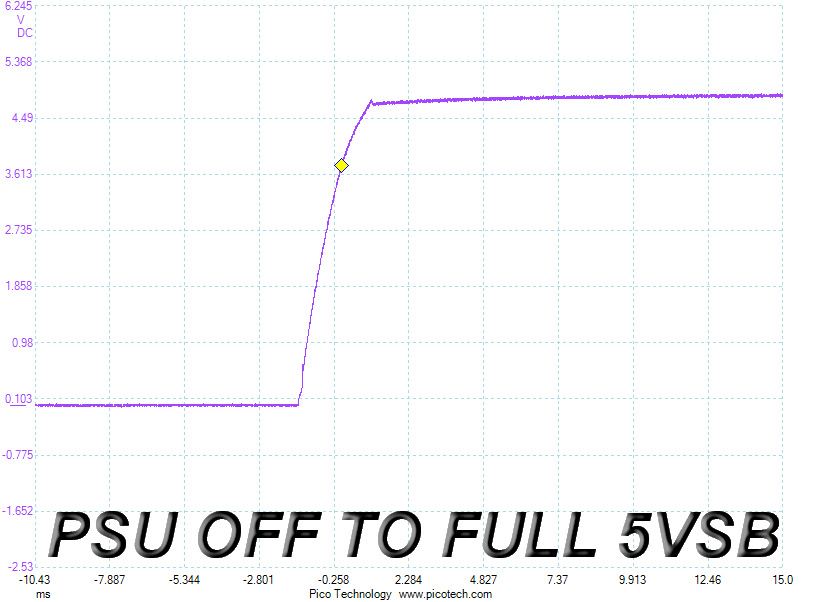
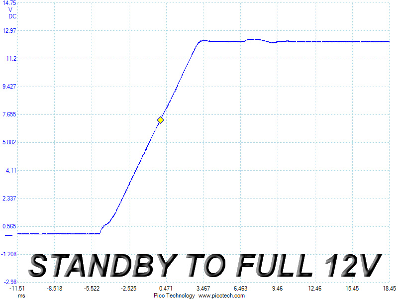
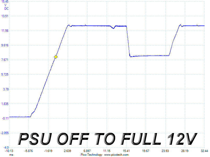
The first two turn-on transient tests went smoothly, but we noticed an unexpected drop on all rails except for 5VSB during the third test, which is a clear indication of a protection kicking in and instantly removing power, but everything did go back to normal afterward. The inrush current control circuit of the PFC controller most likely interfered, and once we dialed a lower load and ran the third turn-on test again, the slope was smooth, so this particular problem only occurs at full load, where inrush current is high. Real-life scenarios are actually unlikely to produce such results, so you have nothing to worry about. However, we will deduct performance points for its failure to comply with our third turn-on transient test, even though this issue is not due to a protection feature kicking in.
Jan 29th, 2025 01:03 EST
change timezone
Latest GPU Drivers
New Forum Posts
- Will you buy a RTX 5090? (223)
- WHEA LOGGER 18(Cache Hierarchy Error) KERNEL POWER 41. READ DESCRIPTION please help (30)
- Free Games Thread (4415)
- Intel Virtualization and TS in 24H2? (2)
- TPU's F@H Team (20400)
- Zotac 4070 Super/7800X3D Stutters (4)
- I dont like my new CPU Cooler (34)
- So who’s paying $100 for GTA 6 then? (80)
- MSI Vector 17 HX A14VIG "EDP OTHER" (2)
- New PCI-E pin on Motherboard (13)
Popular Reviews
- ASUS GeForce RTX 5090 Astral OC Review - Astronomical Premium
- NVIDIA DLSS 4 Transformer Review - Better Image Quality for Everyone
- NVIDIA GeForce RTX 5090 Founders Edition Review - The New Flagship
- MSI GeForce RTX 5090 Suprim Liquid SOC Review
- MSI GeForce RTX 5090 Suprim SOC Review
- Palit GeForce RTX 5090 GameRock Review
- NVIDIA GeForce RTX 5090 PCI-Express Scaling
- KLEVV URBANE V DDR5-7600 32 GB CL36 Review
- AMD Ryzen 7 9800X3D Review - The Best Gaming Processor
- Asus ROG Strix X870-A Gaming Wi-Fi Review
Controversial News Posts
- NVIDIA 2025 International CES Keynote: Liveblog (470)
- AMD Debuts Radeon RX 9070 XT and RX 9070 Powered by RDNA 4, and FSR 4 (349)
- AMD is Taking Time with Radeon RX 9000 to Optimize Software and FSR 4 (239)
- AMD Radeon RX 9070 XT & RX 9070 Custom Models In Stock at European Stores (226)
- NVIDIA GeForce RTX 5090 Features 575 W TDP, RTX 5080 Carries 360 W TDP (217)
- New Leak Reveals NVIDIA RTX 5080 Is Slower Than RTX 4090 (200)
- AMD Denies Radeon RX 9070 XT $899 USD Starting Price Point Rumors (181)
- AMD's Radeon RX 9070 Launch Faces Pricing Hurdles (175)