 6
6
CORSAIR K68 RGB Keyboard + PBT Keycaps Review
Driver »Disassembly
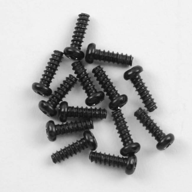

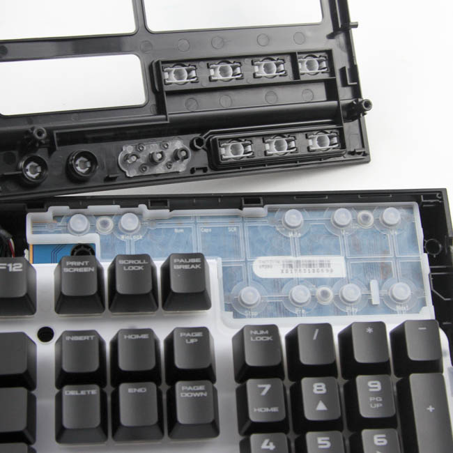
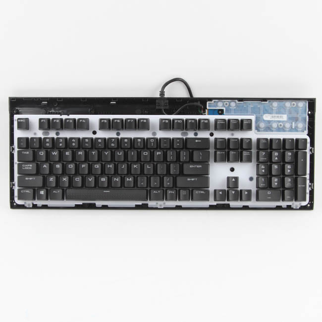
Disassembly of the Corsair K68 begins with the removal of thirteen Phillips head screws that hold the ABS plastic top panel and the rest of the keyboard together. Once done, you have to use a thin, flat object to pry out the top panel locked in place via multiple plastic inserts around the edges. These are better than the small, flat interlocking tabs most keyboards with a plastic case use, and there is less scope for one to break off as well. With that done, we get to see the membrane switches on the top panel piece that help actuate the various media keys.
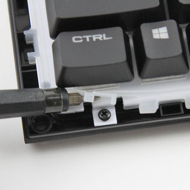
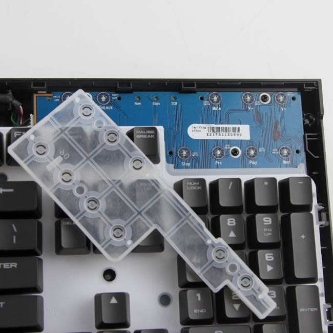
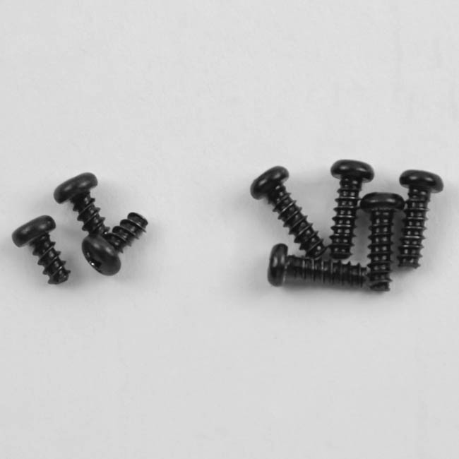
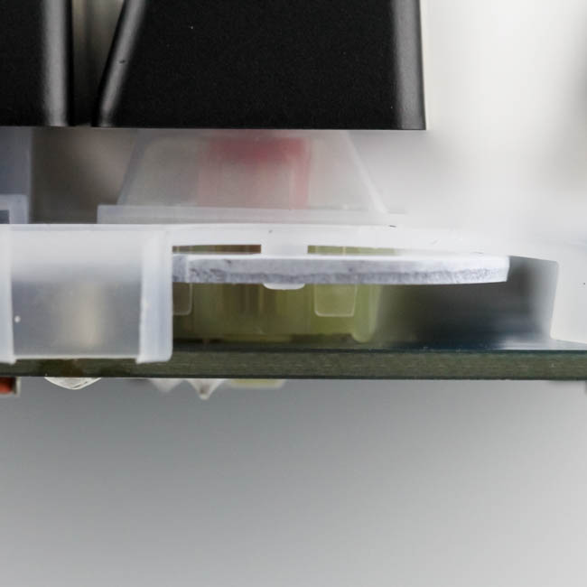
At this point, you can either remove every single keycap to access the white rubber mold and remove them or, having disassembled the older K68 already, only remove specific keycaps to access the seven screws which keep the PCB/plate piece attached to the bottom plastic panel. There are in fact two molds here, a large one for the main keyboard and a second smaller mold for the media keys. Both have a raised edge on all sides to collect any spilled fluids or dust, and the keycaps help guide anything spilled away from the switch housing and LEDs. There is no rubber O-ring seal keeping the PCB and switches completely isolated here, so treat it as you would any other keyboard and just consider there to be a better chance of survival in case of any spillage.
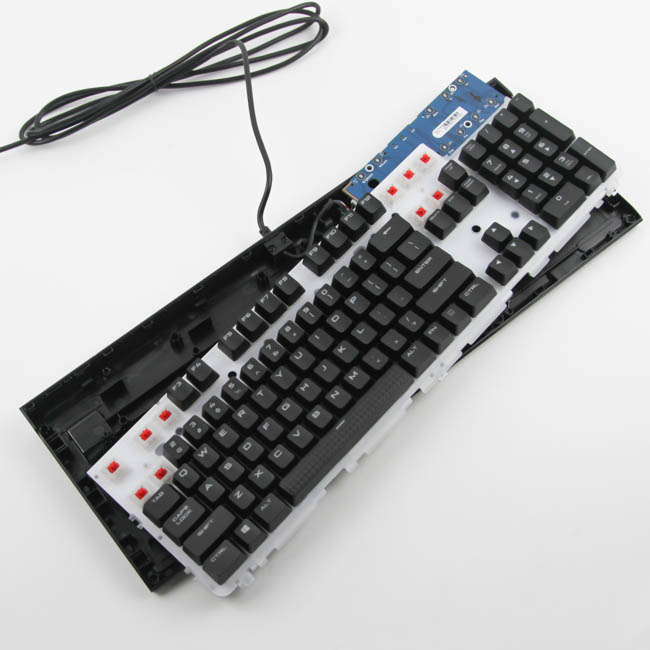
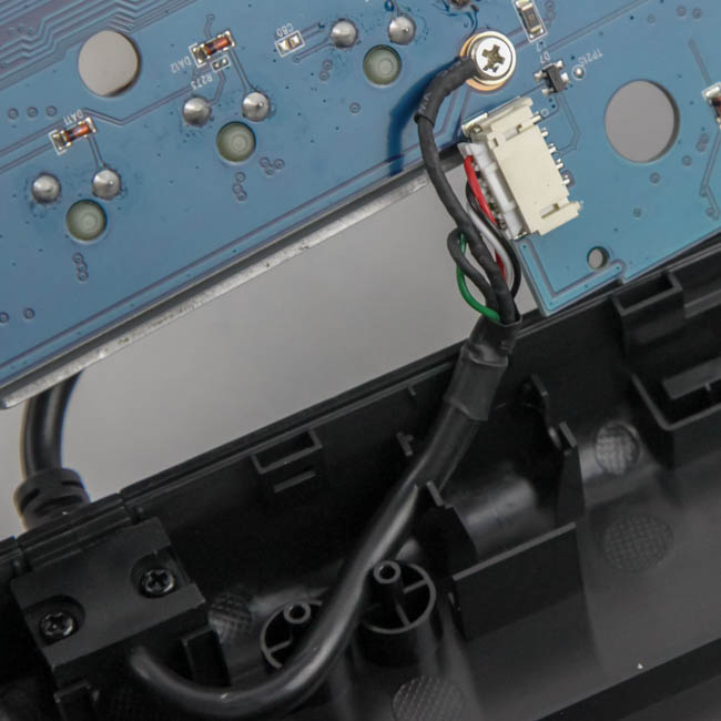
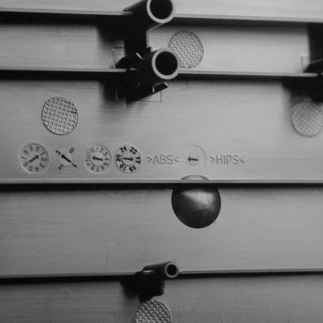
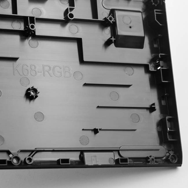
With the final set of screws removed, there is enough room to turn the PCB over. Here, we can see the keyboard cable terminating in an internal USB connector that needs to be disconnected, and a grounding screw also needs to be removed. With that done, one can remove the PCB/plate piece from the case, which is also made out of ABS plastic and gives us a better look at the various channels and cutouts to direct fluids away from the keyboard.
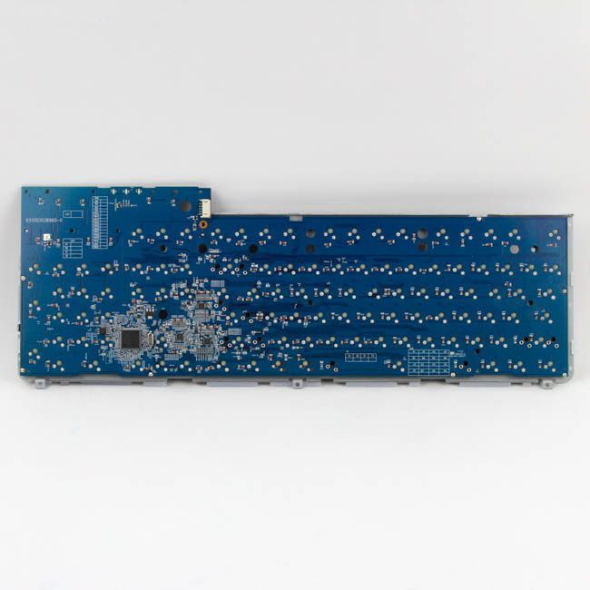
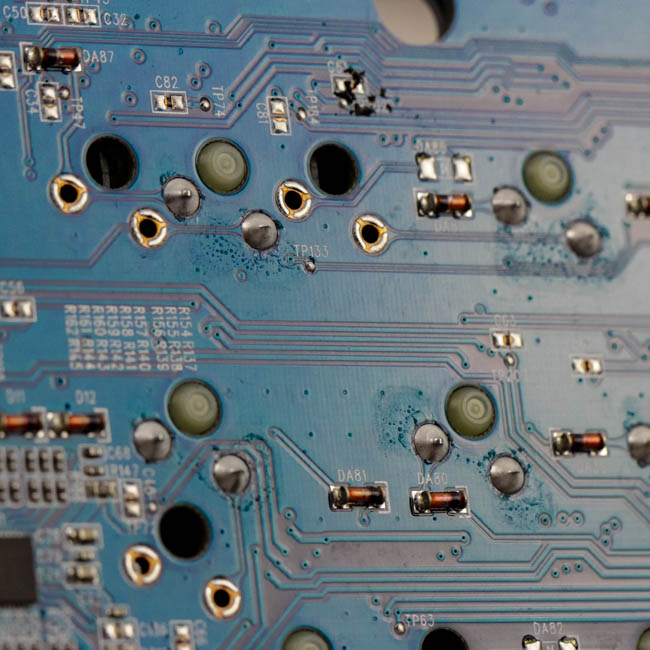
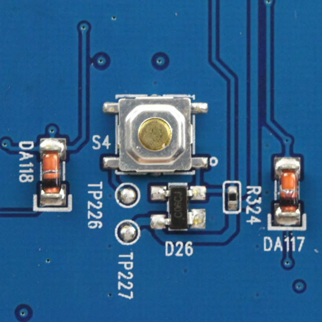
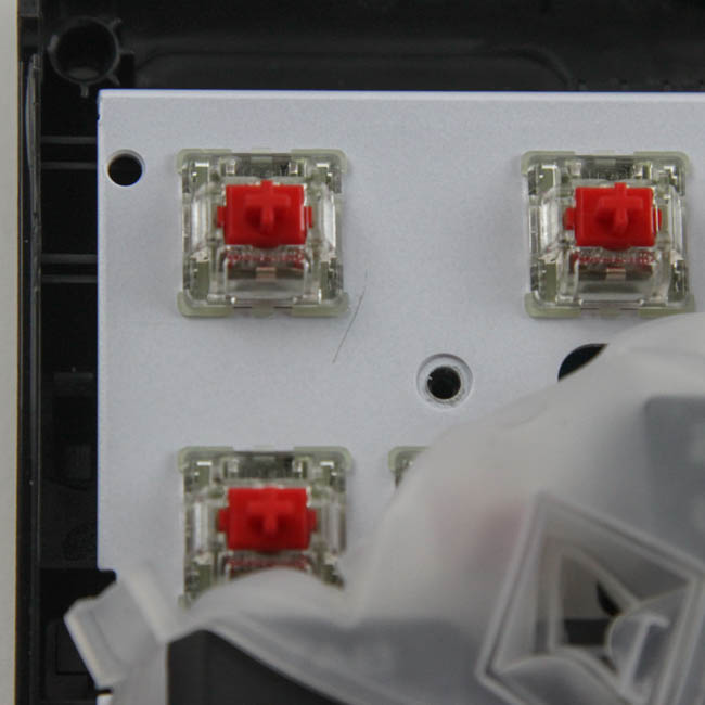
The PCB, blue in color here vs. the green on the non-RGB variant, has an extension at the top to house the media-control section, which means there is a lot of empty space under the case. There are a lot of components here, and they are soldered very well - likely an automated process to handle the volumes CORSAIR deals with. A steel plate helps provide structural integrity to the unit, with the switches being plate mounted through and into the PCB. There is a hardware reset button hiding in the back, accessible through a hole in the back of the keyboard if there are no other alternatives.
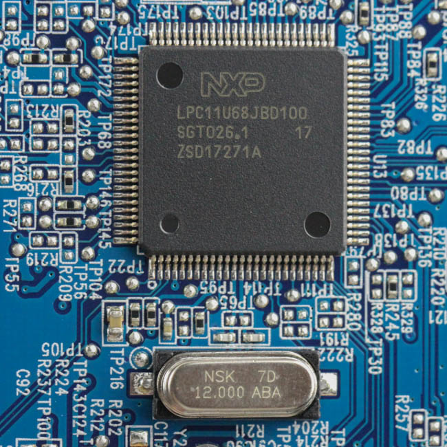
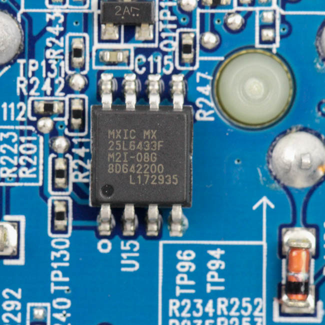
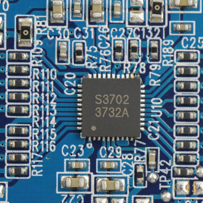
Powering the Corsair K68 is an NXP LPC11U68JBD100 32-bit ARM Cortex-M0+/M0 Cores-based USB microcontroller with 256 KB on-board flash memory and 36 KB SRAM, which is, respectively, twice and thrice as much as on the K68 non-RGB version. There is also a massive Macronix MX25L6433 8 MB flash memory module to store all the pre-programmed functions. All the components, including the switches, LEDs, and capacitors, are soldered to a multi-layered PCB.
Before we move on, be advised that disassembly will void the warranty and that TechPowerUp is not liable for any damages incurred if you decided to go ahead and do so anyway.
Mar 10th, 2025 18:07 EDT
change timezone
Latest GPU Drivers
New Forum Posts
- Please I need help with the poor performance that my PC is giving me (32)
- I'm looking for a good tool to make the 3D scanning of my mini-pc using the photogrammetry and my Kinect 2. (53)
- Maxsun RX580 graphics card crashes (29)
- What is a good real price for the RTX 5090? (23)
- Microcenter GPU Stock status (31)
- Biostar RX 6700 XT OC BIOS (0)
- Msi 5090 DOA? (28)
- DLSS as antialiasing? (23)
- Cryptocoin Value and Market Trend Discussion (1646)
- Fix for Vram frequency always at maximum (0)
Popular Reviews
- Sapphire Radeon RX 9070 XT Nitro+ Review - Beating NVIDIA
- XFX Radeon RX 9070 XT Mercury OC Magnetic Air Review
- ASUS Radeon RX 9070 TUF OC Review
- MSI MAG B850 Tomahawk Max Wi-Fi Review
- NVIDIA GeForce RTX 5080 Founders Edition Review
- NVIDIA GeForce RTX 5070 Founders Edition Review
- Corsair Vengeance RGB CUDIMM DDR5-8800 48 GB CL42 Review
- AMD Ryzen 7 9800X3D Review - The Best Gaming Processor
- ASUS GeForce RTX 5070 Ti TUF OC Review
- MSI GeForce RTX 5070 Ti Gaming Trio OC+ Review
Controversial News Posts
- NVIDIA GeForce RTX 50 Cards Spotted with Missing ROPs, NVIDIA Confirms the Issue, Multiple Vendors Affected (513)
- AMD Plans Aggressive Price Competition with Radeon RX 9000 Series (277)
- AMD Radeon RX 9070 and 9070 XT Listed On Amazon - One Buyer Snags a Unit (261)
- AMD RDNA 4 and Radeon RX 9070 Series Unveiled: $549 & $599 (260)
- AMD Mentions Sub-$700 Pricing for Radeon RX 9070 GPU Series, Looks Like NV Minus $50 Again (248)
- NVIDIA Investigates GeForce RTX 50 Series "Blackwell" Black Screen and BSOD Issues (244)
- AMD Radeon RX 9070 and 9070 XT Official Performance Metrics Leaked, +42% 4K Performance Over Radeon RX 7900 GRE (195)
- AMD Radeon RX 9070-series Pricing Leaks Courtesy of MicroCenter (158)