 3
3
Enermax Revolution X't 630 W Review
Voltage Regulation, Hold-up Time & Inrush Current »A Look Inside & Component Analysis
Before reading this page, we strongly suggest a look at this article, which will help you understand the internal components of a PSU much better. Our main tool for the disassembly of the PSU is a Thermaltronics TMT-9000S soldering and rework station. It is of extreme quality and is equipped with a matching de-soldering gun. With such equipment in hand, breaking apart every PSU is like a walk in the park!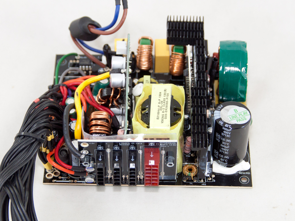

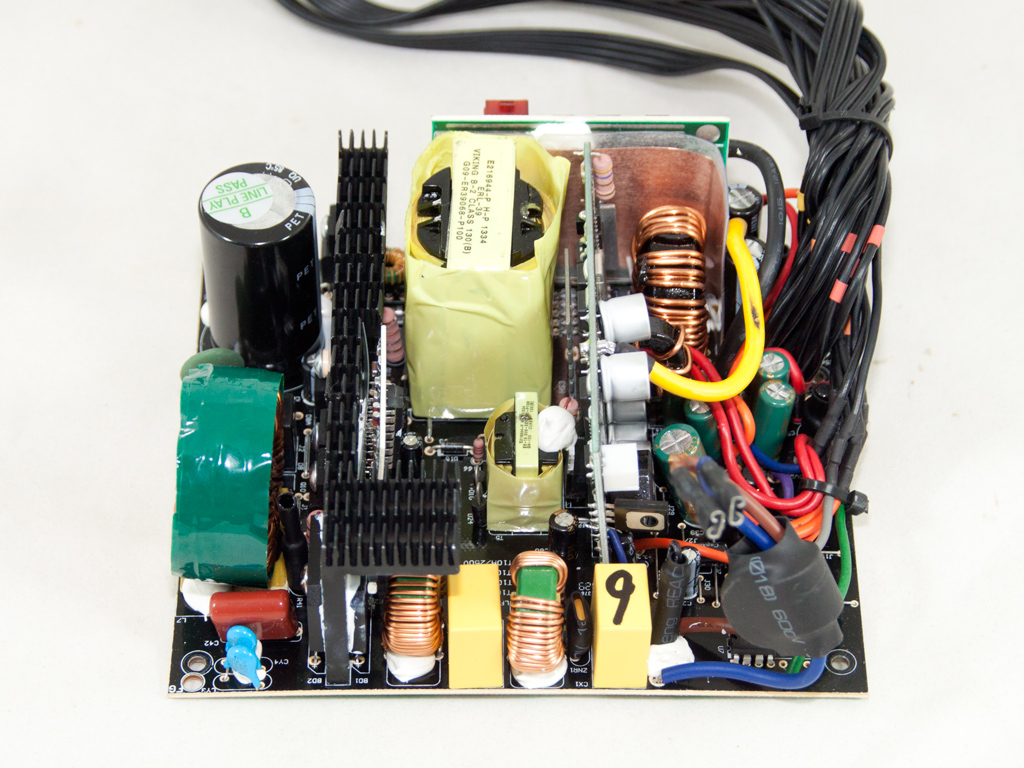
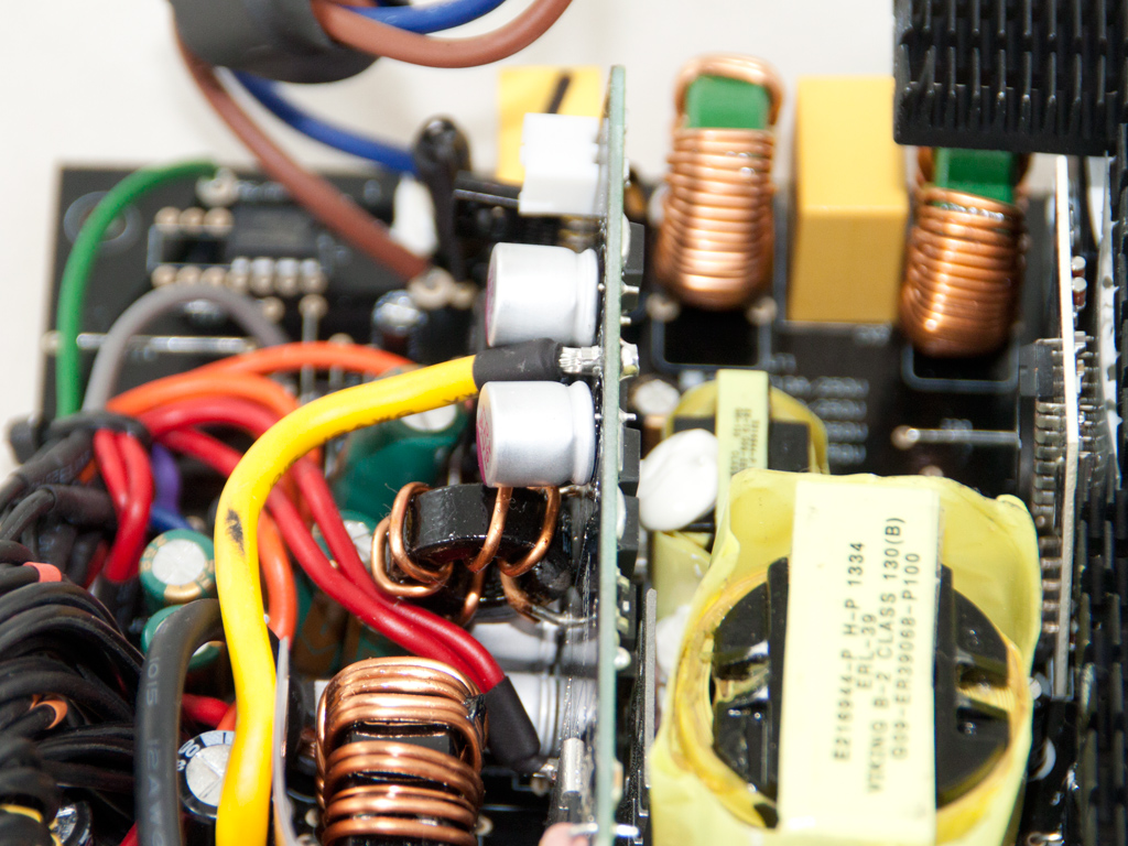
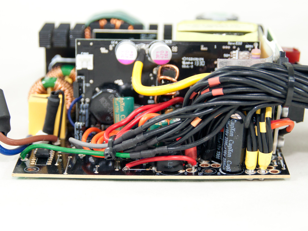
This platform was designed and implemented by Enermax, and the first things to strike the eye are that it is underpopulated and lacks heatsinks in the secondary side. A plain topology is used in the primary side, while two DC-DC converters generate the minor rails in the secondary side.
A pair of Y caps starts the transient filter at the AC receptacle, and it continues on the main PCB with two X caps, a pair of Y caps after the bridge rectifier, two CM chokes, and a small MOV (Metal Oxide Varistor), which is the little but valuable component providing protection against spikes from the power network grid.
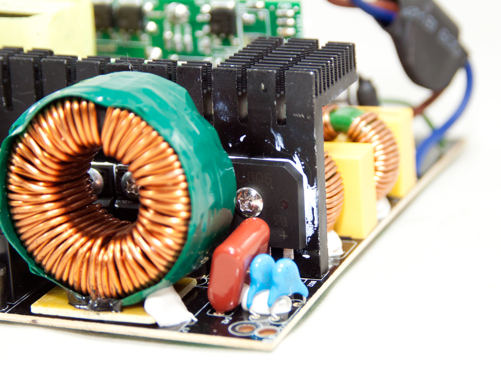

There are two parallel bridge rectifiers (GBU806) which, combined, can handle up to 16 A of current.
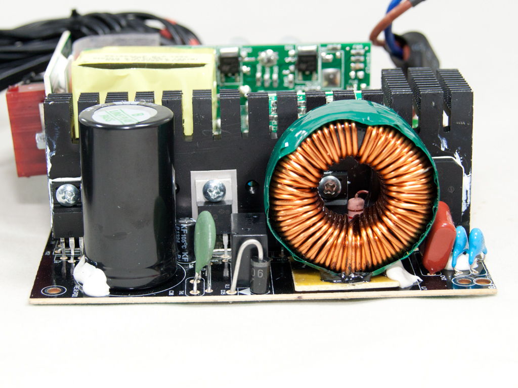
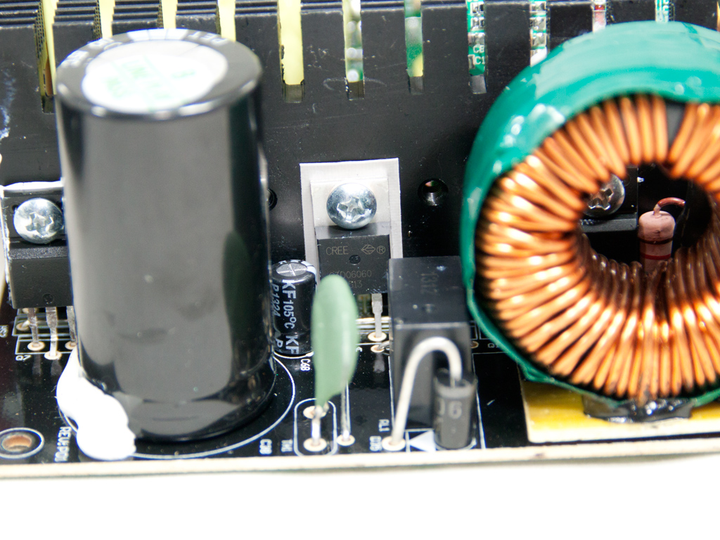
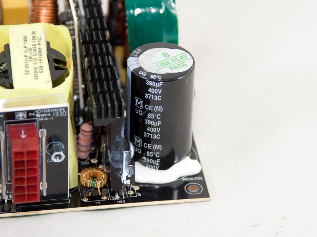
Two Vishay SIHF22N60E-E3 mosfets and a CREE C3D06060A boost diode in the APFC shape the input current sinusoidal. The bulk cap is provided by Panasonic (400 V, 390 μF, 85°C), and its capacity looks really small for this PSU.
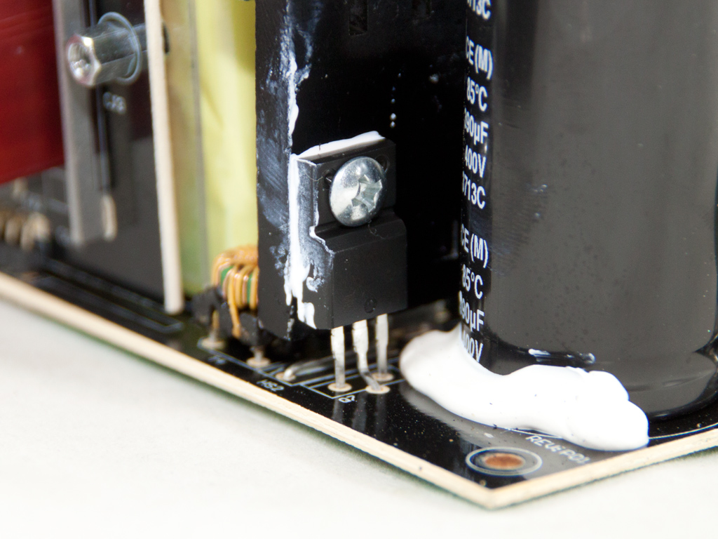
Two Vishay SIHF22N60E-E3s act as primary switchers.
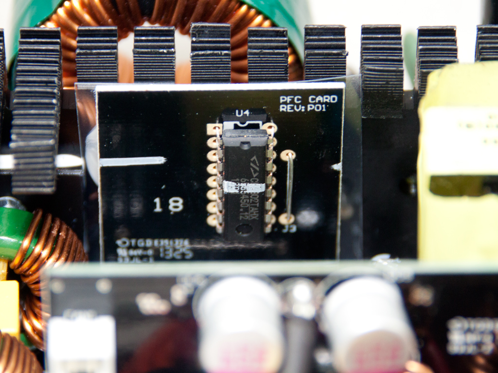
The combo PFC/PWM controller is a Champion CM6802 IC.
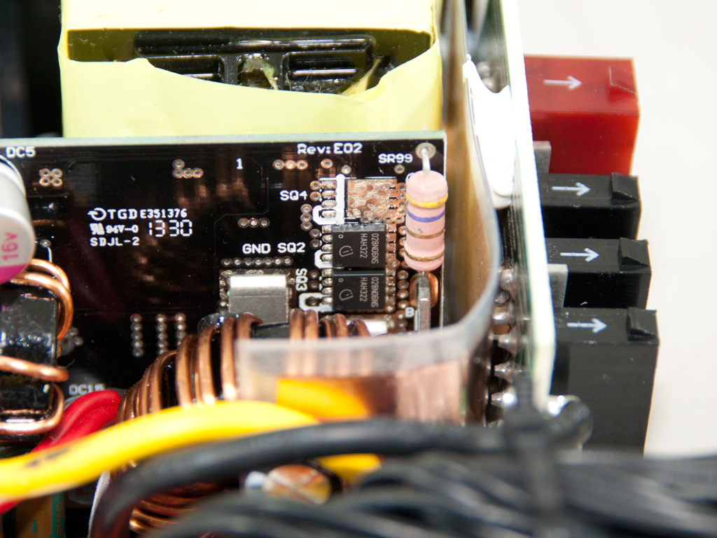
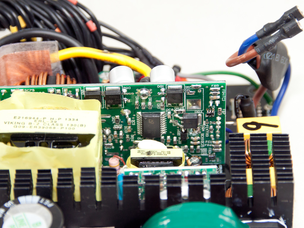
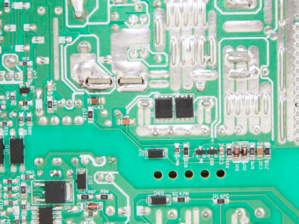
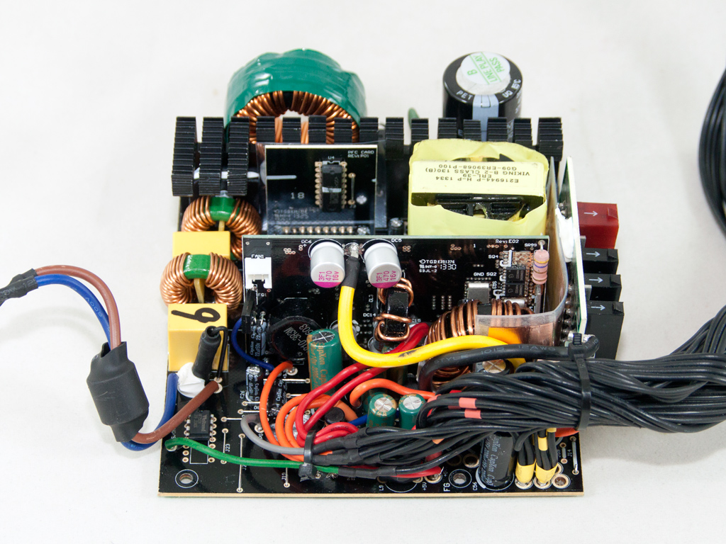
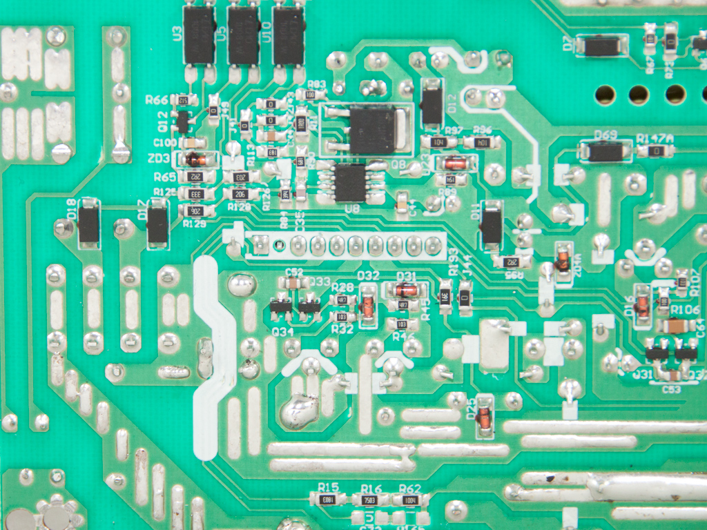
There are no heatsinks in the secondary side, and a large daughter-board holds two out of the four fets rectifying the +12V rail and the pair of DC-DC converters generating the minor rails. Two pairs of Infineon BSC028N06NS fets are used for +12V. One is located, as already mentioned, on the aforementioned daughter-board while the second is installed on the solder side of the mainboard.
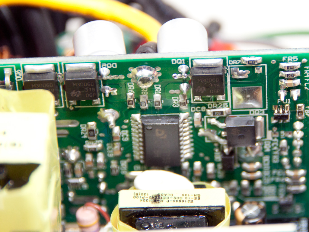
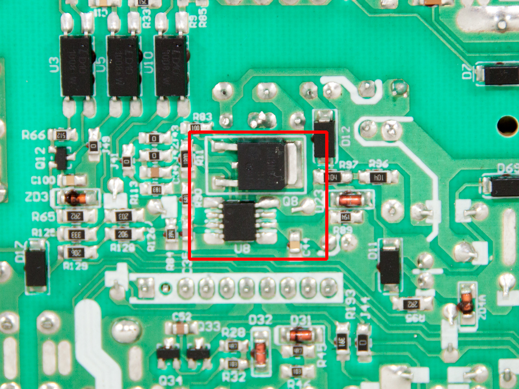
The two DC-DC converters generating the minor rails use five M3006Ds and an APW7159 PWM controller.
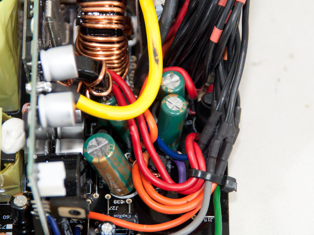
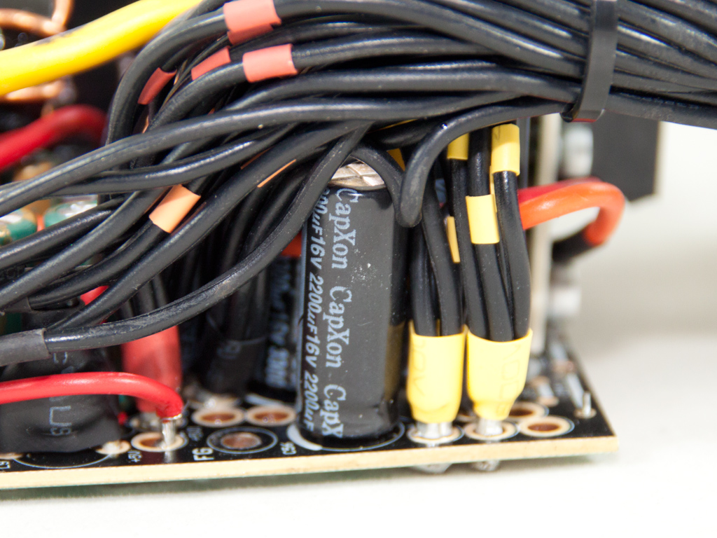
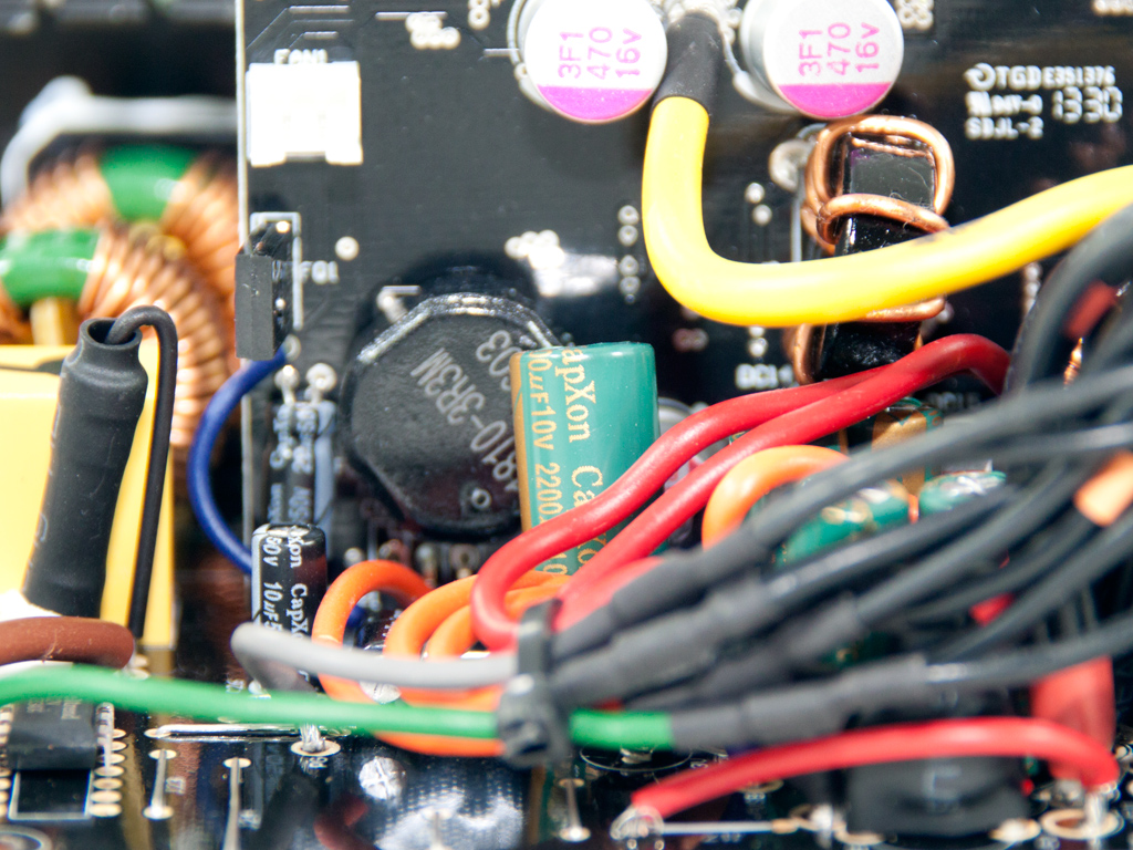
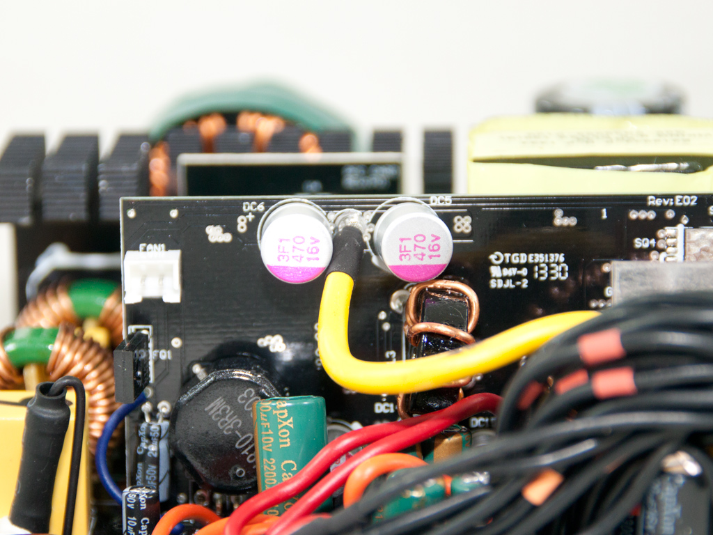
All electrolytic caps in the secondary side are provided by CapXon. We also found Enesol polymer caps on the VRMs.
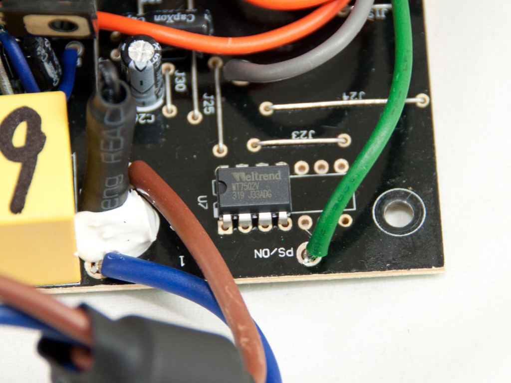
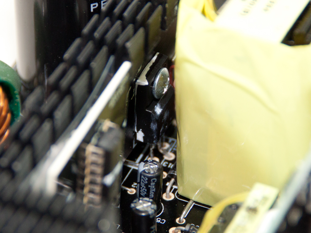
The protections IC is soldered directly to the main PCB, and it is a Weltrend WT7502V IC; it only provides the very basic protections.
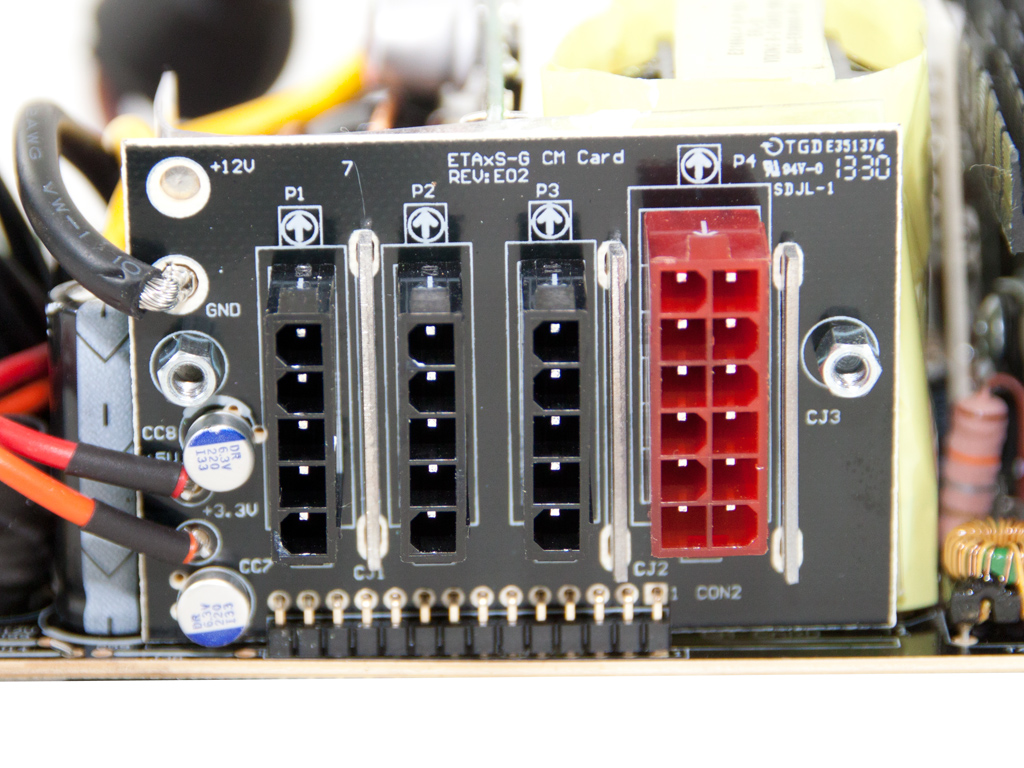
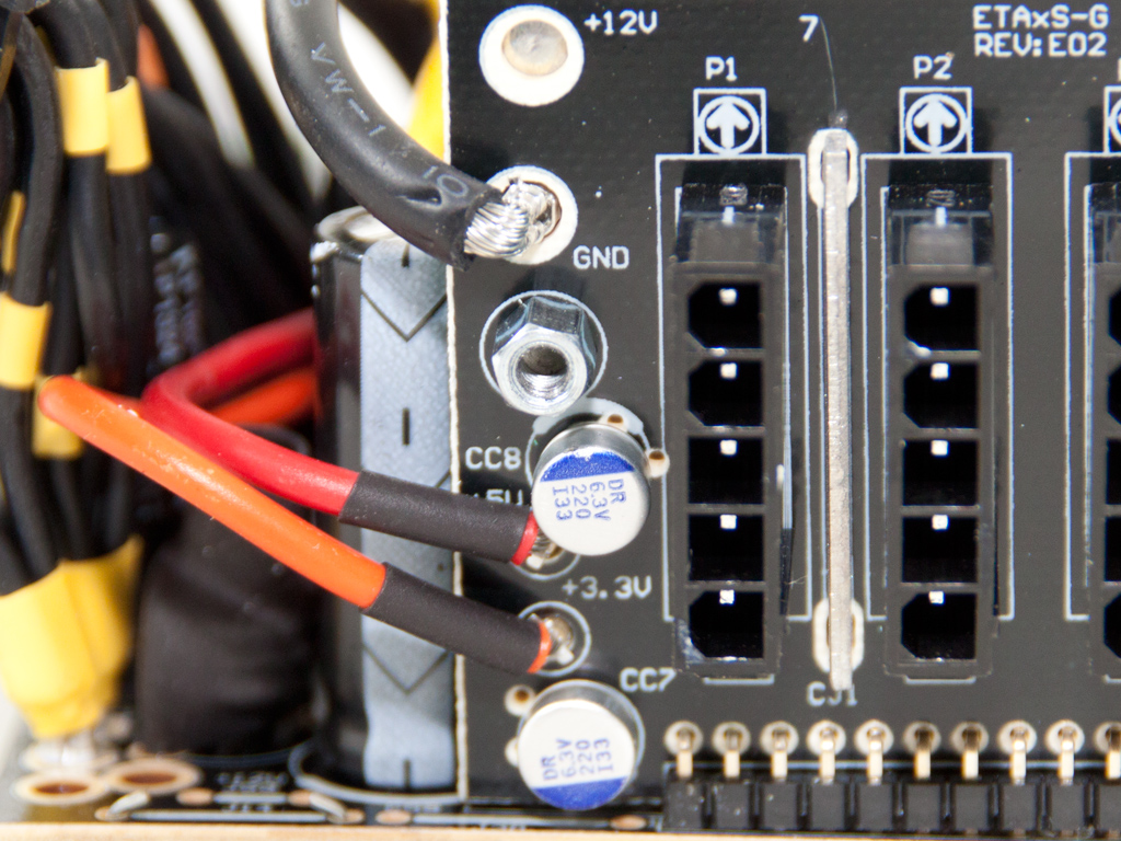
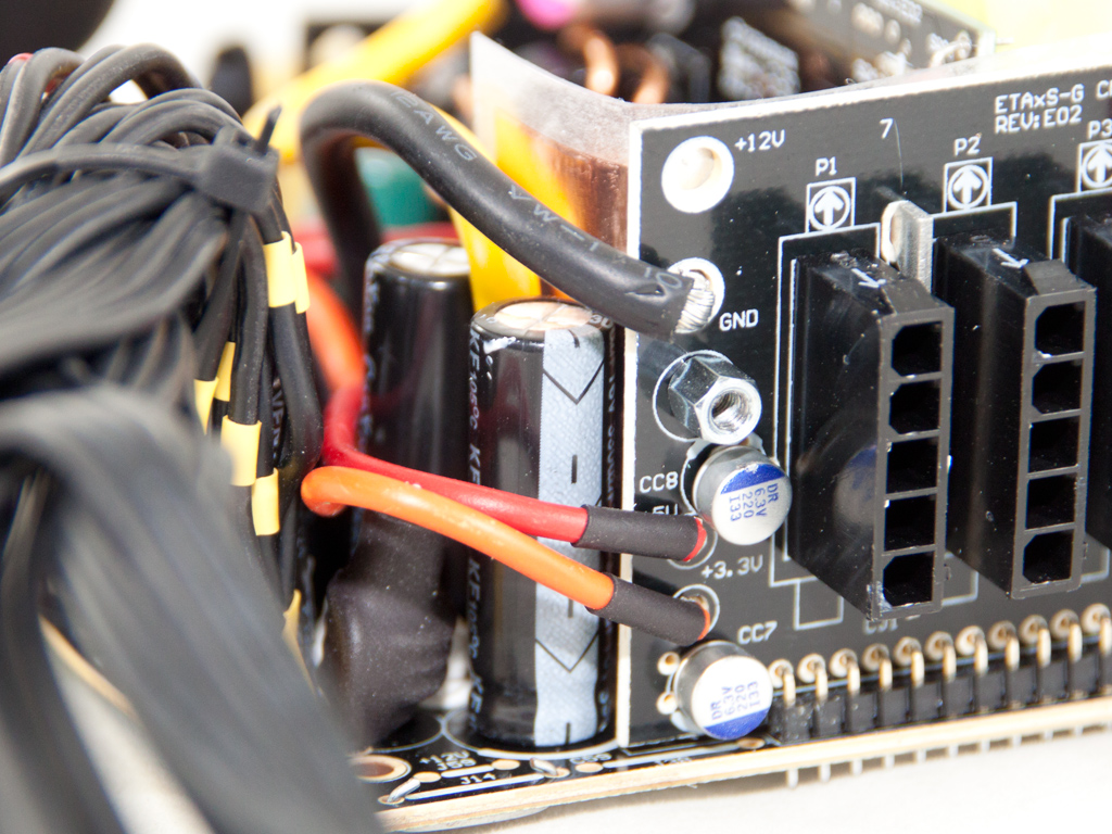
The modular PCB is small and hosts two polymer capacitors to help with ripple filtering. We were still unable to identify the maker of these DR caps, so everyone with a clue on these is invited to help.
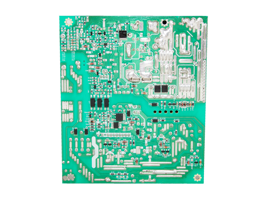
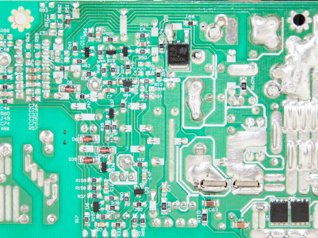
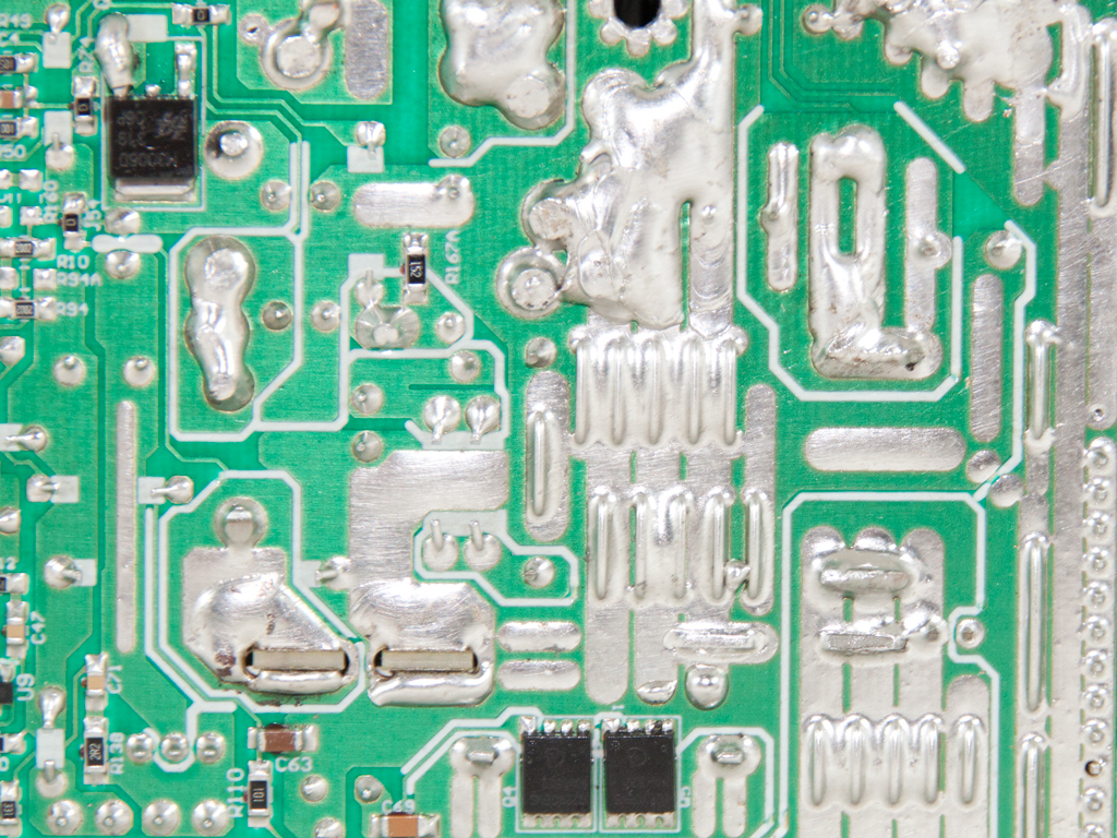
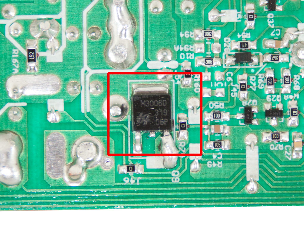
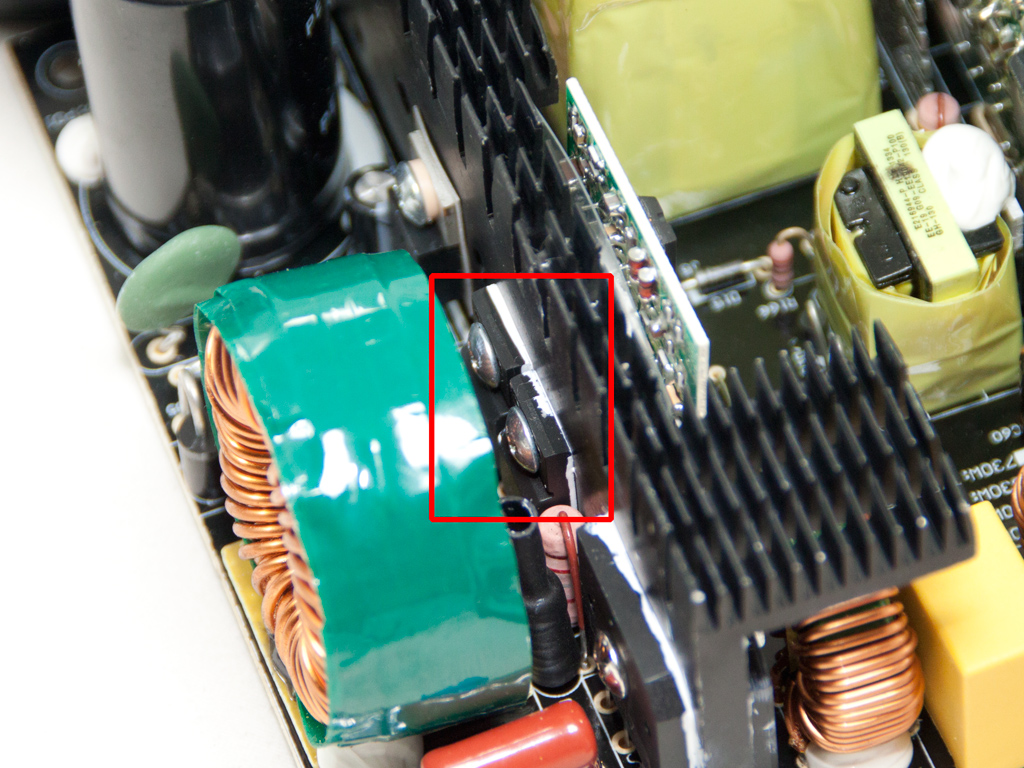
Soldering quality on the main PCB is decent, although we spotted several sloppy soldering jobs. The main PCB also holds the mosfet used by the 5VSB circuit, an M3006D, and another, exactly the same, whose purpose is a mystery.
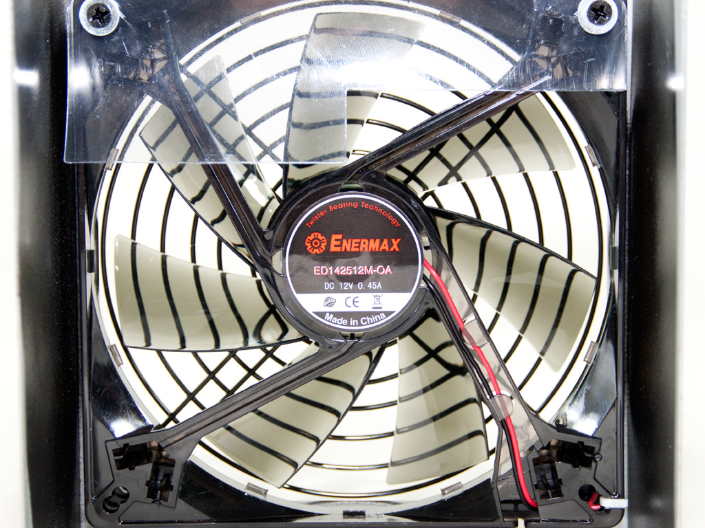
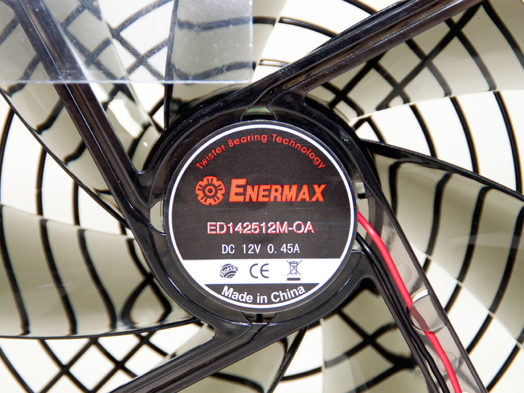
The cooling fan is provided by Enermax, and its model number is ED142512M-0A (139mm, 12 V, 0.45 A). It uses twister bearings and is, according to Enermax, effective and silent. Our tests will clearly show whether Enermax's statement holds true.
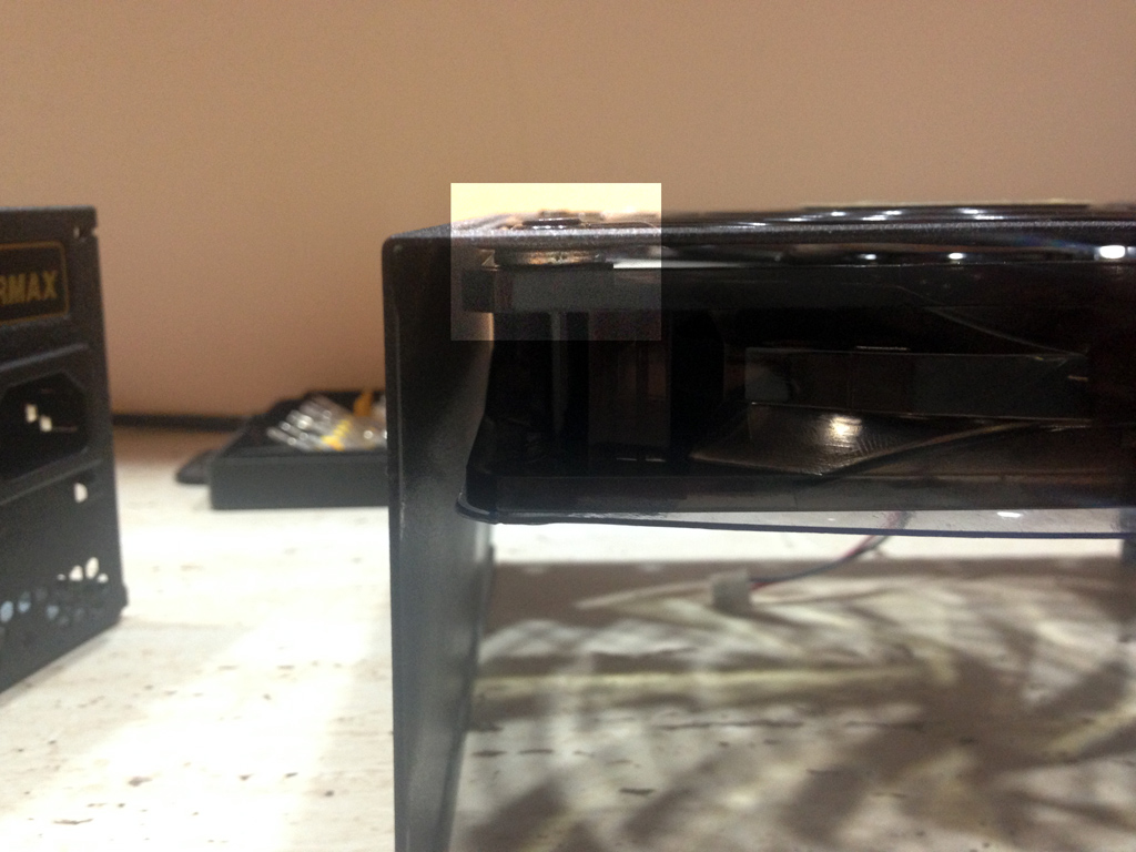
We noticed that the fan's blades touch the fan frill, a problem that got worse as its speed increased, during our fan measurements and with the fan facing downward. Considering that the PSU compartment is in most cases located at the bottom, it is more efficient to install the unit with the fan facing down, dragging air from outside the case, which would have this deficit turn into a major flaw. We installed four washers between the fan and the casing to compensate, which panned out as everything functioned normally afterward. We got in touch with Enermax on this issue. They are already aware of this problem and will fix it before the unit hits retail, yet we thought we should mention it since we stumbled upon it.
Feb 2nd, 2025 18:14 EST
change timezone
Latest GPU Drivers
New Forum Posts
- Interest in Foldathons? (33)
- RTX 5090 ridiculous price! (120)
- RTX 5080 - premature review - it sucks (226)
- Wow YouTube is a Hog (13)
- Testing max ram overclock pn Ryzen 1700 (40)
- GameTechBench GPU benchmark is already out! (254)
- remove hum from active subwoofer? (34)
- TECHPOWERUP HWBOT Contest Submissions List (52)
- Optane performance on AMD vs Intel (32)
- Post your Anvil's Storage score for SSD (52)
Popular Reviews
- NVIDIA GeForce RTX 5080 Founders Edition Review
- Spider-Man 2 Performance Benchmark Review - 35 GPUs Tested
- Galax GeForce RTX 5080 1-Click OC Review
- NVIDIA DLSS 4 Transformer Review - Better Image Quality for Everyone
- MSI GeForce RTX 5080 Vanguard SOC Review
- ASUS GeForce RTX 5080 Astral OC Review
- Gigabyte GeForce RTX 5080 Gaming OC Review
- MSI GeForce RTX 5080 Suprim SOC Review
- ASUS GeForce RTX 5090 Astral OC Review - Astronomical Premium
- NVIDIA GeForce RTX 5090 Founders Edition Review - The New Flagship
Controversial News Posts
- NVIDIA 2025 International CES Keynote: Liveblog (470)
- AMD Debuts Radeon RX 9070 XT and RX 9070 Powered by RDNA 4, and FSR 4 (349)
- AMD Radeon 9070 XT Rumored to Outpace RTX 5070 Ti by Almost 15% (255)
- AMD is Taking Time with Radeon RX 9000 to Optimize Software and FSR 4 (251)
- AMD Denies Radeon RX 9070 XT $899 USD Starting Price Point Rumors (239)
- AMD Radeon RX 9070 XT & RX 9070 Custom Models In Stock at European Stores (226)
- NVIDIA GeForce RTX 5090 Features 575 W TDP, RTX 5080 Carries 360 W TDP (217)
- New Leak Reveals NVIDIA RTX 5080 Is Slower Than RTX 4090 (215)