 33
33
Gigabyte X570S AERO G Review
VRM Overview »Board Layout

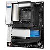
Now that it is out of the box, we can get a closer look the Gigabyte X570S AERO G. First thing that sticks out the most may be the overall design. Sometimes a motherboard can fall into the trap of form over function. Here however, Gigabyte understands this isn't just to be shown off, as it still needs to provide a solid user experience. Therefore, it has no lighting implemented into the motherboard. The thought process here is that you shouldn't be staring at a light show, instead work should be the focus. The blue sections over the Rear IO and chipset can also be a bit deceiving into thinking it is lit up, but it is just blue plastic with a reflective coating and not illuminated.

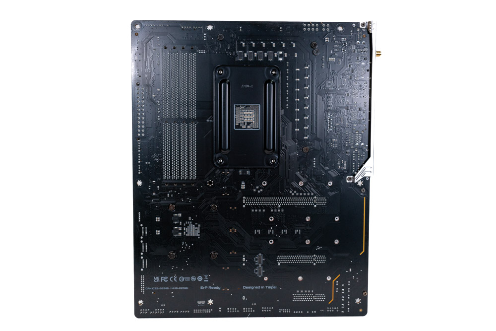
The Gigabyte X570S AERO G offers two x16 slots, both of which are reinforced for extra stress support from heavy graphic cards. One additional x16 slot is placed at the bottom that is for less heavy add-on cards. Because the AM4 platform has a set number of PCIe lanes provided by the CPU, many compromises had to be made here, which will become apparent further along. It is not unique to this motherboard at all and echoed throughout this review.
Going down from the top, the first PCIe x16 is the only one truly internally wired for x16 PCIe Gen4. The second slot shares the same PCIe lanes and is physically wired for x8 PCIe Gen4. When the second slot is populated, the first will drop to x8 PCIe Gen4 as well due to sharing the same PCIe lanes from the CPU. The last x16 slot, may be able to hold a full-size add-on card as well, but is internally wired for x4 PCIe Gen4. This slot also becomes disabled when the third M.2 socket is populated.

Gigabyte deploys four M.2 Gen4 x4 sockets on the AERO G motherboard. Depending where each M.2 drive is installed determines what else on the motherboard gets disabled. When all the M.2 sockets are populated, The 3rd PCIe slot (For M.2C) and SATA 6 Gb/s 4-5 ports (For M.2D) become disabled due to the PCIe lanes being repurposed for two of these M.2 sockets.
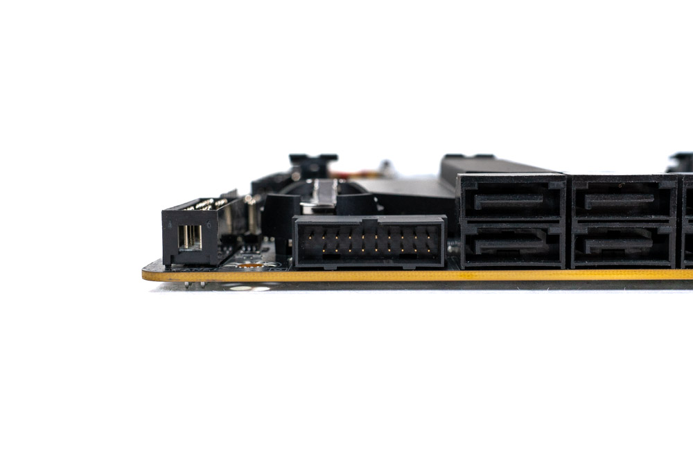
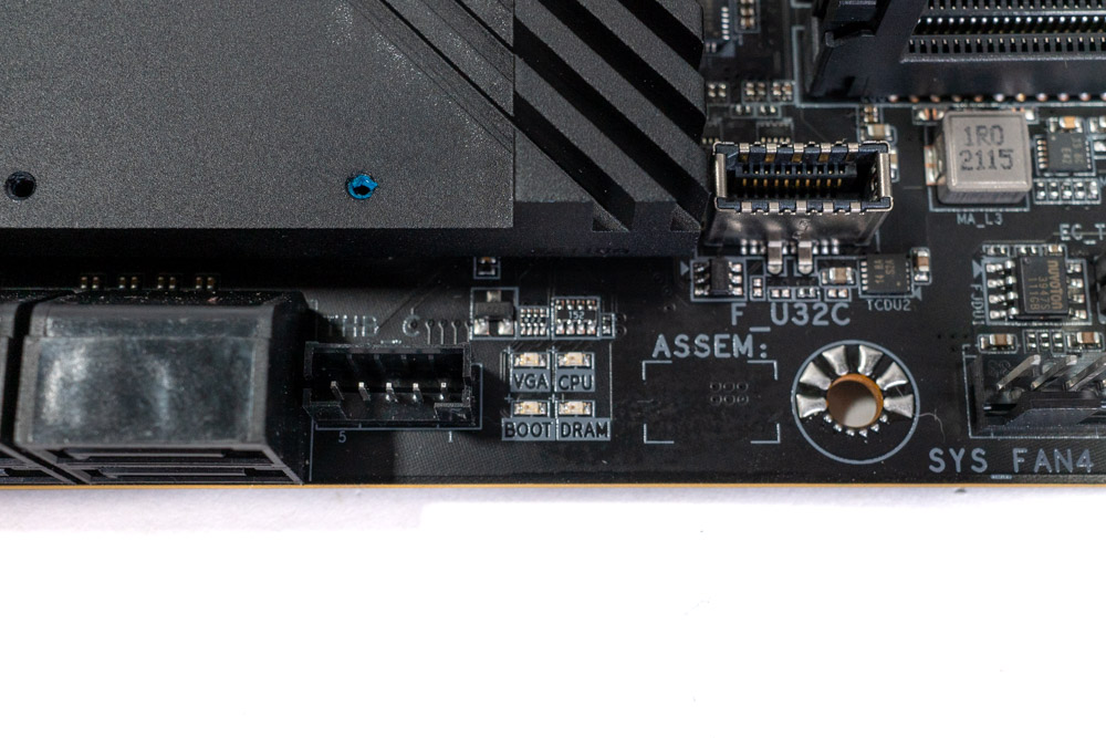
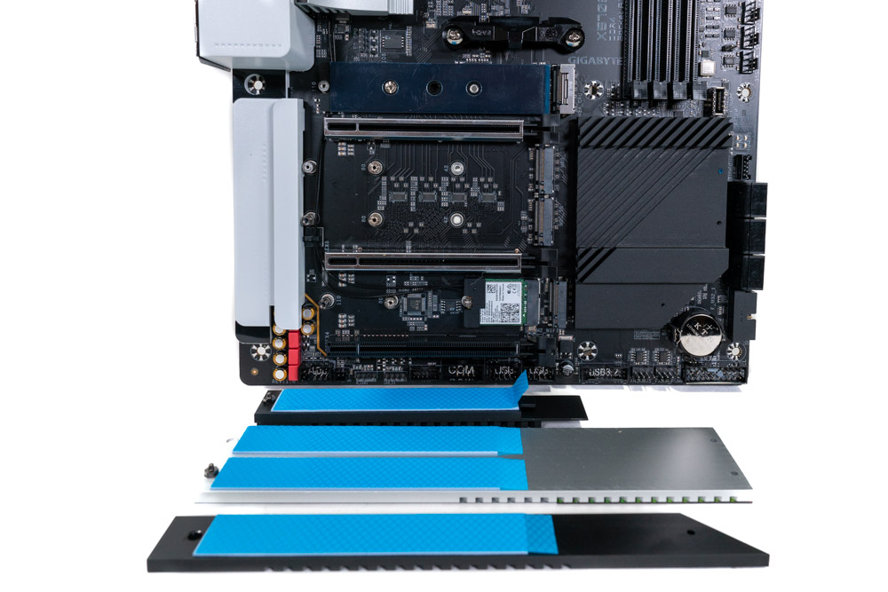
The Gigabyte X570S AERO G has two USB 3.2 Gen 1 (5 Gbps) and two USB 2.0 headers. An internal USB 3.2 Gen 2x1 (10 Gbps) Type-E header is included as well. Gigabyte also has included a Thunderbolt header (THB_C) for the Gigabyte Thunderbolt Add-in card(s) as well. Note; this will still require the use of a x4 PCIe slot.
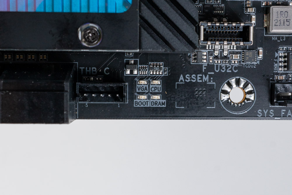
The Gigabyte X570S AERO G uses debug LEDs to troubleshoot boot problems. A Debug post-code display is missing, which is helpful for technical troubleshooting, but unnecessary for basic common issues. As the system goes through the startup, each LED will turn on indicating what part of the startup process it is on. If say for example the motherboard is having an issue with the memory, it will stop on the memory LED indefinitely until the system is power cycled (consult the manual for more information).

This motherboard has an 8-pin EPS and a 4-pin EPS power connector. Above the EPS connectors is a plastic cover that can be easily removed and is only to hide the cables for a cleaner look.
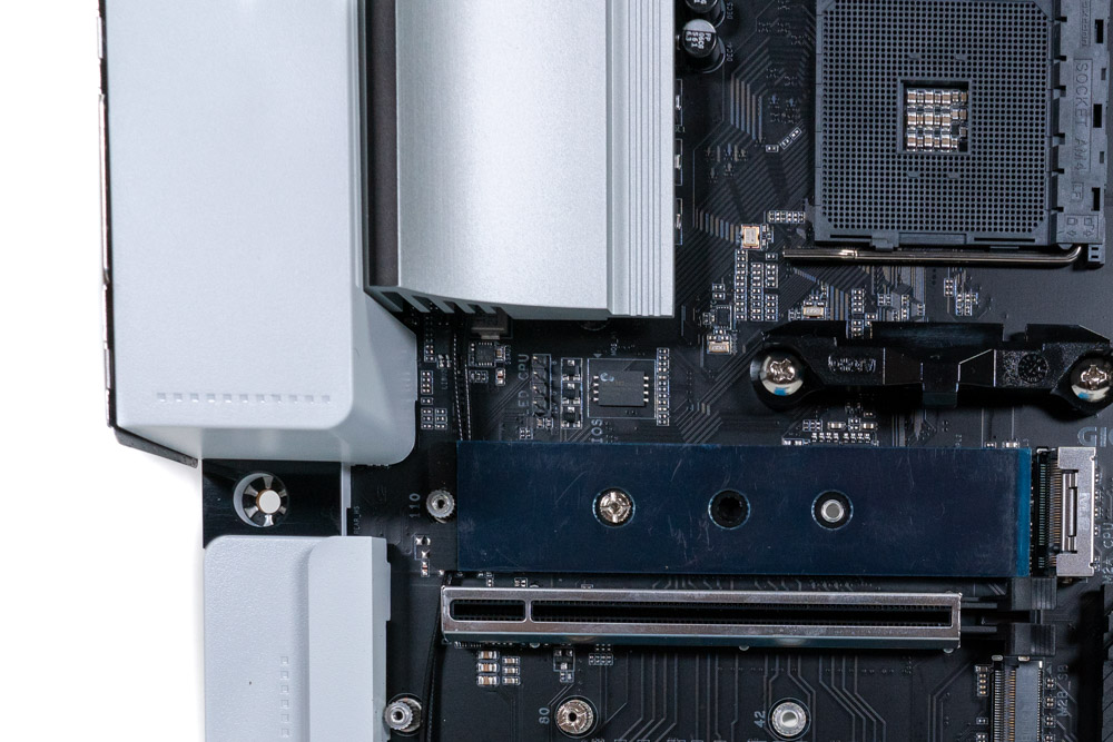


While the motherboard itself has no RGB LEDs to speak of, it does include five headers to connect these types of devices. Whether that is case fans, CPU cooler or case lighting, the X570S AERO G has the ability to connect to these devices for full RGB control. One 12 V header is placed near the CPU socket. At the point and bottom two RGB headers can be found as well. One is 5 V while the other is 12 V compliant per set.

Often this little white button can be found on the Rear IO panel. It goes by many different names as each motherboard vendor comes up with a new one for marketing purposes. But it functions the same none the less. Gigabyte calls this button Q-Flash Plus. It is pretty straight forward once you know what it is. Q-Flash allows you to update the BIOS when your system is off (while the motherboard is still powered). Put a USB flash in the corresponding USB port with the AERO G BIOS, press the button and wait until the LED stops flashing. It is that simple and easy.
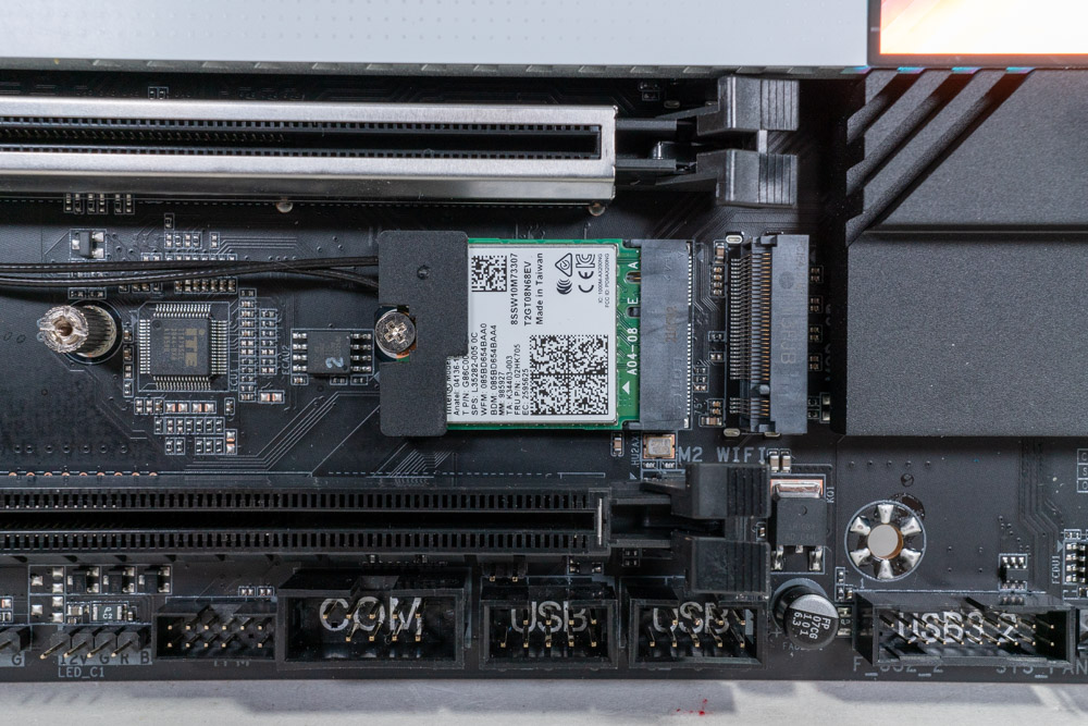
Gigabyte has placed the Wi-Fi card separate from the Rear IO. This is much more common in laptops due to space restrictions, but can be designed this way on the desktop as well.
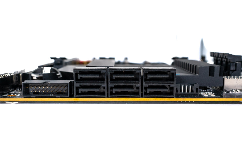
The board has a total of six SATA 6 Gb/s ports on the side, angled 90 degrees from the board. Two of these ports become disabled once a M.2 NVMe SSD is installed in the 4th M.2 socket (M.2D).
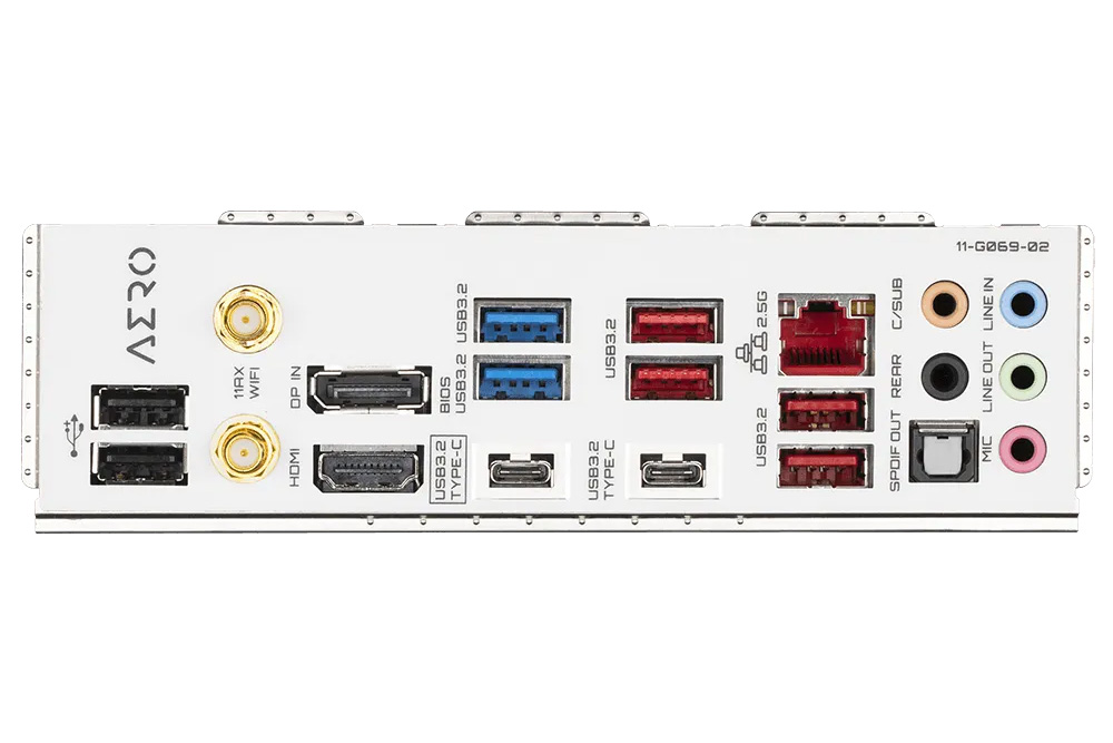
The Gigabyte X570S AERO G has an assortment of ports that should provide enough bandwidth for a majority of content creators. Absent is the inclusion of Thunderbolt 4, which is often found on motherboards marketed towards prosumers. Instead a single USB 3.2 Type-C (20 Gbps) port is available to be used with a USB hub and can carry a display signal up to 4096x2304@60 Hz. If that isn't enough bandwidth, four USB 3.2 Gen 2 10 Gbps ports (Red) and two USB 3.2 Gen 2 5 Gbps (Blue) ports is available as well.
An HDMI port that supports 4096x2304@60 Hz and a DisplayPort (In) port is present as well. The DisplayPort is a bit confusing because it is for input only. It allows any DisplayPort video signal to be routed through the motherboard to the USB-C port as stated in the manual. Last up on the panel is the antenna for Wi-Fi 6, S/PDIF Out, and 2.5 GbE LAN.
- 2x USB 2.0/1.1 ports
- 2x SMA antenna connectors (2T2R)
- 1x HDMI port
- 1x DisplayPort In port
- 1x USB Type-C® port, with USB 3.2 Gen 2x2 support
- 1x USB Type-C® port, with USB 3.2 Gen 1 support
- 4x USB 3.2 Gen 2 Type-A ports (Red)
- 2x USB 3.2 Gen 1 ports (Blue)
- 1x RJ-45 port
- 1x optical S/PDIF Out connector
- 5x audio jacks
Feb 4th, 2025 18:29 EST
change timezone
Latest GPU Drivers
New Forum Posts
- Is this 5950x running correctly? (2)
- Help:Pc suddenly shut down, Now can’t turn on (11)
- Astral 5080 Power limit (5)
- I7 11800h success (0)
- Hello everyone, what HDMI cable do you recommend to connect a PC(5090 GPU) with a 120HZ TV? (7)
- What's a good test for a thermal glue? (7)
- 7900XTX Thermal pad size? (1)
- 64GB (C)UDIMMs, where are they? (31)
- Ubisoft Health Watch (12)
- What are you playing? (22747)
Popular Reviews
- Spider-Man 2 Performance Benchmark Review - 35 GPUs Tested
- Corsair Frame 4000D Review
- NVIDIA GeForce RTX 5080 Founders Edition Review
- MSI GeForce RTX 5080 Vanguard SOC Review
- Gigabyte GeForce RTX 5080 Gaming OC Review
- ASUS GeForce RTX 5080 Astral OC Review
- NVIDIA DLSS 4 Transformer Review - Better Image Quality for Everyone
- MSI GeForce RTX 5080 Suprim SOC Review
- AMD Ryzen 7 9800X3D Review - The Best Gaming Processor
- Cooler Master X Silent Edge Platinum 850 W Review - Fully Passive PSU
Controversial News Posts
- NVIDIA 2025 International CES Keynote: Liveblog (470)
- AMD Debuts Radeon RX 9070 XT and RX 9070 Powered by RDNA 4, and FSR 4 (349)
- AMD Radeon 9070 XT Rumored to Outpace RTX 5070 Ti by Almost 15% (282)
- AMD is Taking Time with Radeon RX 9000 to Optimize Software and FSR 4 (256)
- AMD Denies Radeon RX 9070 XT $899 USD Starting Price Point Rumors (239)
- Edward Snowden Lashes Out at NVIDIA Over GeForce RTX 50 Pricing And Value (233)
- AMD Radeon RX 9070 XT & RX 9070 Custom Models In Stock at European Stores (226)
- New Leak Reveals NVIDIA RTX 5080 Is Slower Than RTX 4090 (215)